|
[#1]
kick ass thread!
|
|
|
|
[#2]
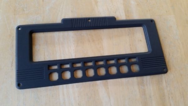
Primered
 |
|
|
|
[#3]
That pic is crap

|
|
|
|
[#4]
Painted the back brown like it was originally although nobody will see it
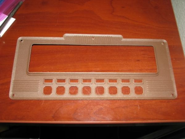 Front painted. Clear coat at some point but it will look the same after. 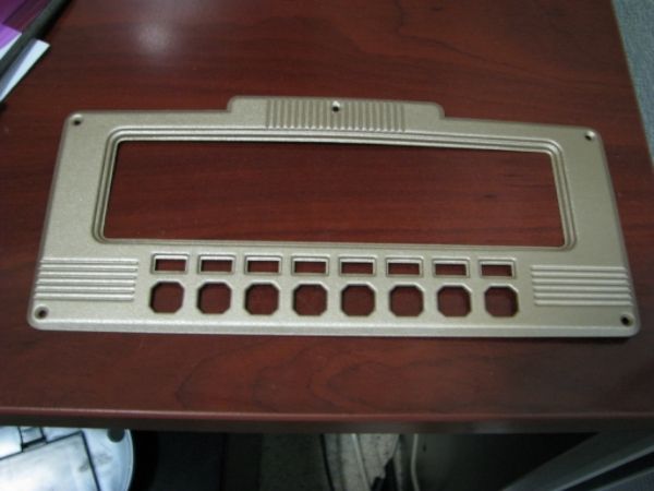 |
|
|
|
[#5]
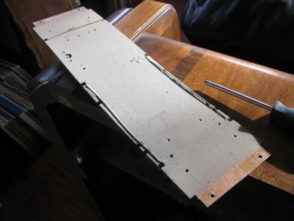
Decided to take the antenna out today and dust it off.
 The antenna is supposed to be wrapped in a wire mesh to reduce noise but this one is missing. I'm going to just clean it up, rewire it where needed, and wrap it in some heavy stock. The mesh is not really all that important. More shots of the dust. Top Some of the flaking wiring that will need to be replaced can be seen here. 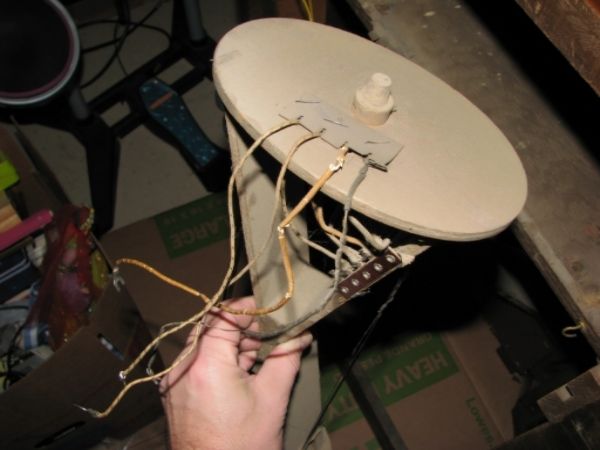 Bottom You can see there is a peg missing. Those pegs fit through the cutout you see there to the right. It keeps the antenna from rotating all the way around. 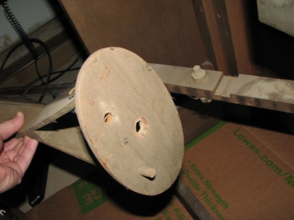 In the sink about to get hosed 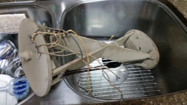 After 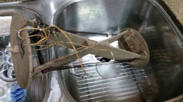 |
|
|
|
[#6]
Some further antenna work.
The loop windings were held together by some sort of tape that has all been lost except one. I replaced the 4 that I can tell had existed. 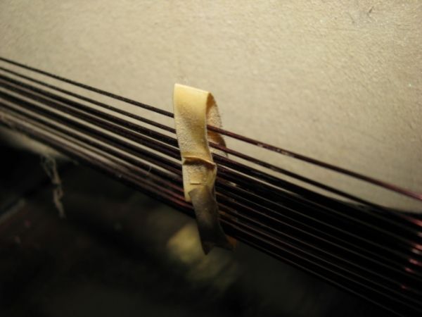 Here is how those new taped sections came out. 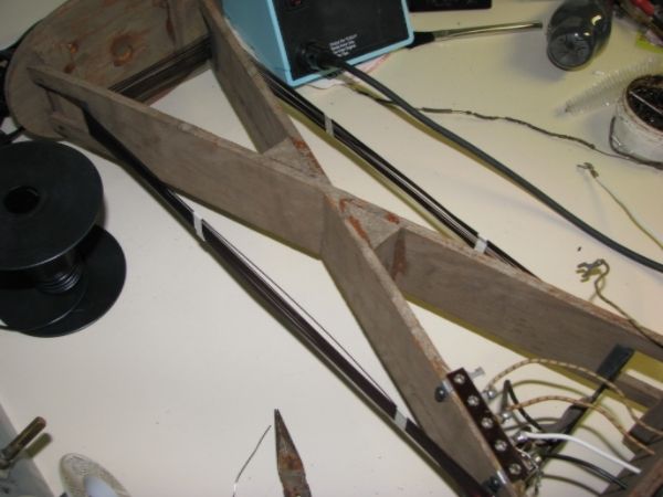 Here are the two new white and black wires. The old ones were dry and flaking. 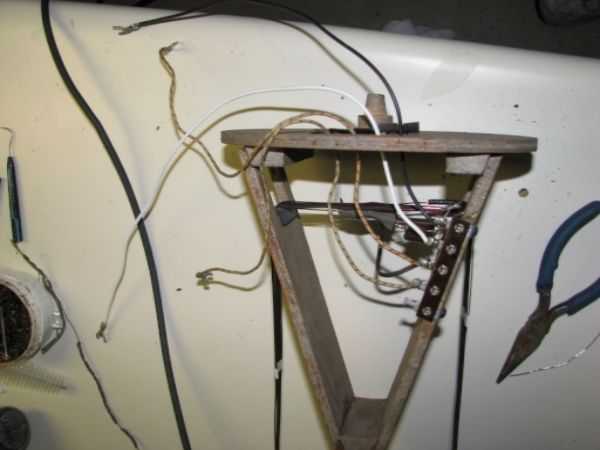 Here is the one missing stopper hole. I cut out a new one from a dowel and will glue it in. 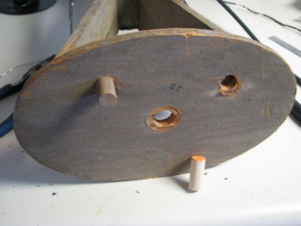 Here it is glued in place 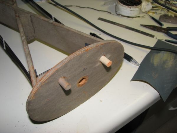 The paper on the right is what I am going to use to wrap the antenna. 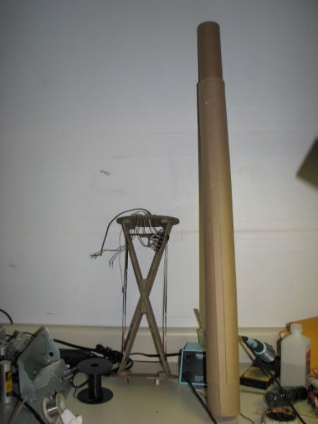 I also needed to paint the face plate screws when I did the face so here they are getting done up. 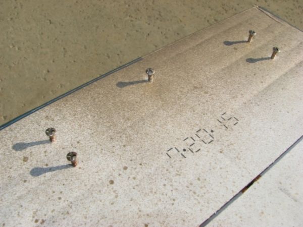 |
|
|
|
[#7]
Sorry guys
Weather has been bad for doing cabinet work and have not been able to order radio parts until tonight. Parts should be incoming tomorrow and I'll update when those come in. Cabinet work will resume when it gets a little warmer and dryer out. |
|
|
|
[#8]
Woohoo parts arrived
I hope to get some of these in this weekend. Might be tough w/ football and all ;) 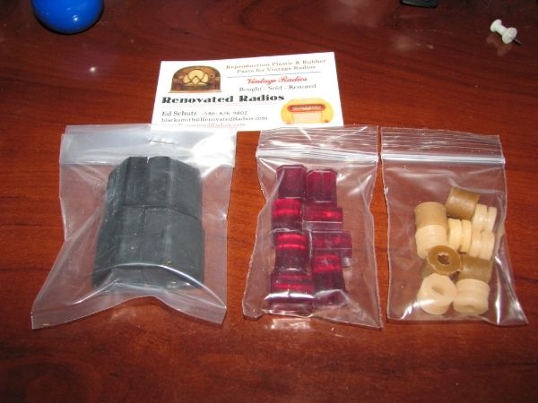 |
|
|
|
[#9]
We had some sun today so I clear coated some pieces.
Here is the antenna. I'll end up covering it up in a cardboard looking stock soon. 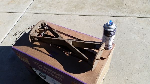 Here is the variable capacitor bracket, dial support, and variable capacitor. Only coating the wheel of the capacitor. 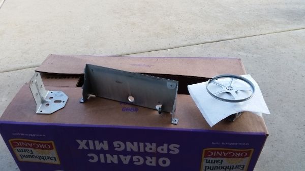 Brought the cabinet (right) inside so I can start looking it over and do any repairs before I start stripping. Yes I like to do some of the work inside. Also the garage is still a disaster after moving. 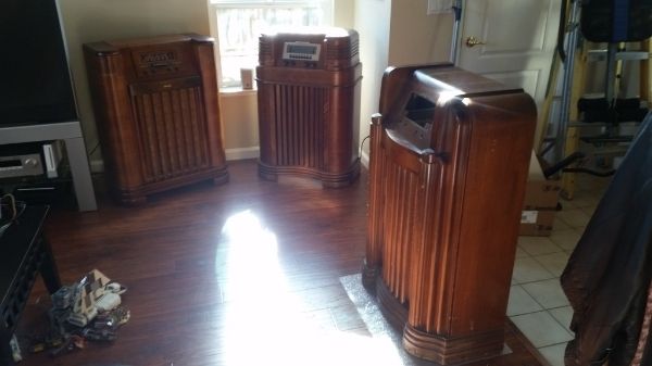 |
|
|
|
[#10]
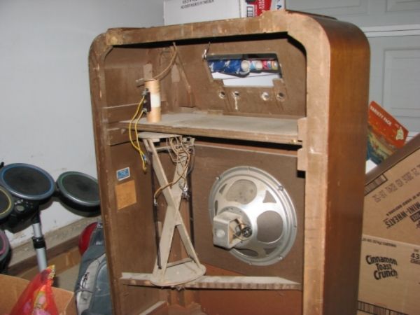
Time to start cabinet cleanup
 Speaker and grill cloth removed 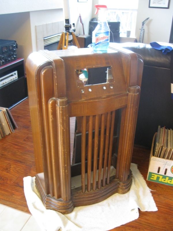 Speaker a tad dusty 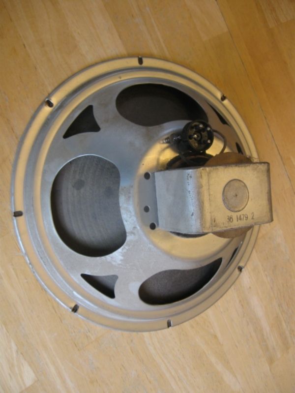 That is a bit better. I'll go over it some more and give it a shot of clear coat. 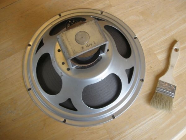 |
|
|
|
[#11]
Almost forgot about the top mounted antenna.
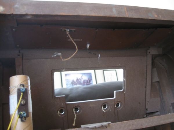  After cleaning 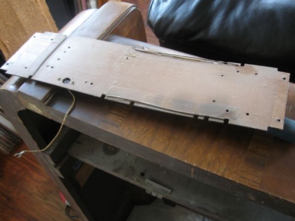 This wire has lost almost all of the insulation. This will need to be replaced. 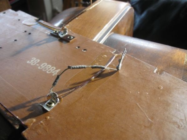 |
|
|
|
[#12]
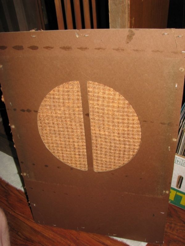
Here is the crap cloth someone put on at some point. Certainly not original or even close.
 Chassis all ready for some clear coat. After pic pretty much the same being clear and all ;) 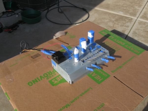 Put the new rubber feet on 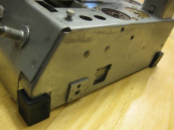 Mounted the variable capacitor along w/ new bushings  The same type of bushings are used on the push button mechanism. They were toast as well. 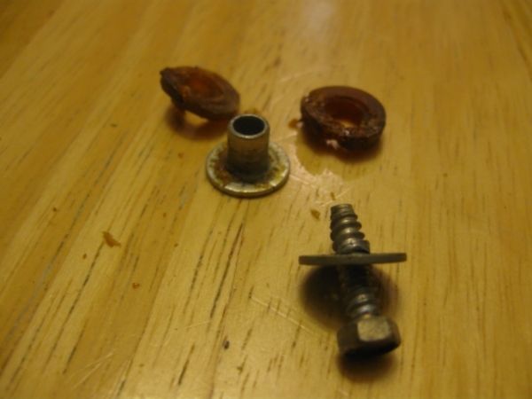 Here the new ones are installed 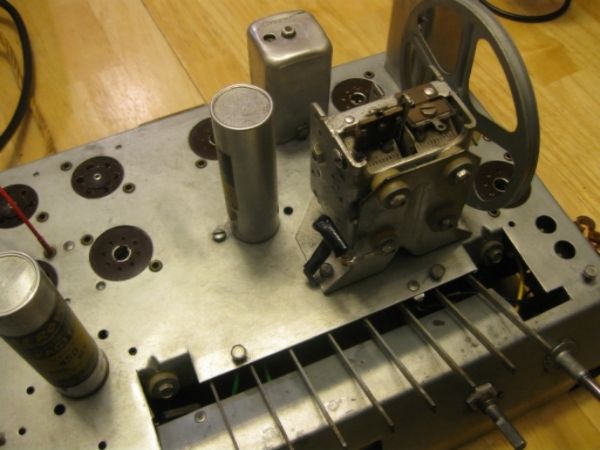 Installed the dial glass support as well 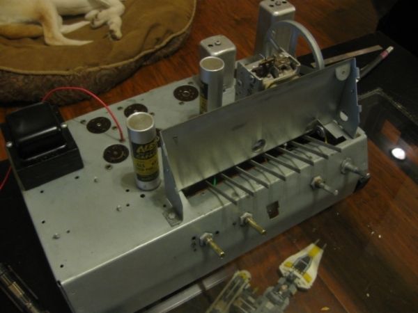 Getting there |
|
|
|
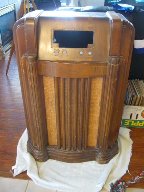
[#13]
Looking good. Could you post some details of the work involved in refinishing the cabinet? After reading your radio threads I suddenly found myself on Craigslist. Picked up two "desktop"(?) radios. One wood and the other bakelite. Also picked up a Crosley floor model. Each were had for $20.00 or less.
|
|
|
|
[#14]
I'll do what I can ;)
I'm no expert so take from it what you want. First thing you usually want to do is repair any missing or loose and any other separated wood. Some light dusting to get to the area might be needed. Some people are lucky enough, after doing the repairs, that the cabinet is just really dirty. Non-pumas GoJo hand cleaner is the go to cleaner for these cabinets. Apparently its not good to clean w/ GoJo first because it can be tougher to get out of areas that you are about to glue together. What I have had to do since my cabinets were to far gone is strip them all the way down and start new. We'll get into that in a bit. |
|
|
|
[#15]
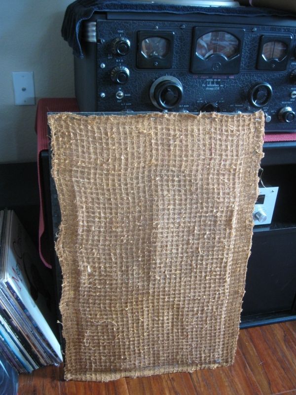
I wrapped up the antenna tonight.
Originally the covering incorporated a wire mesh to cut down on interference but this one was gone when I got it. No mesh here but at least it looks somewhat original. 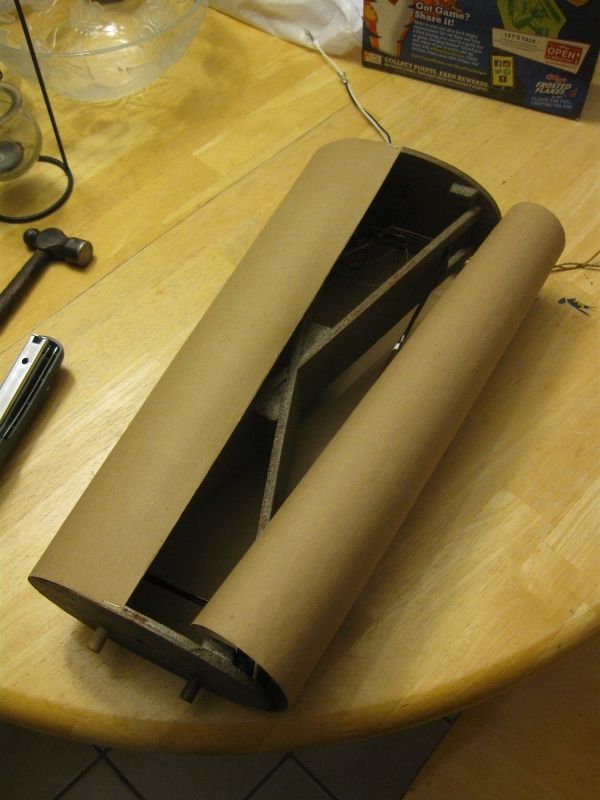 I covered the seam up w/ whatever this tape is. Drywall tape? You have to wet it for it to stick. 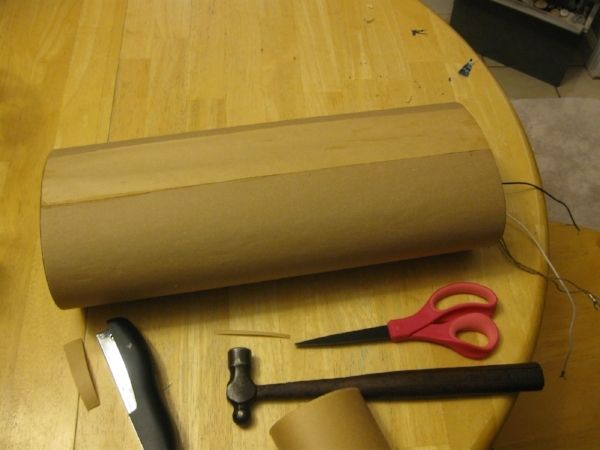 All done. 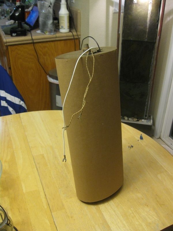 |
|
|
|
[#16]
Put the dial string and needle back on tonight. Also testing out the new buttons and original knobs. I am missing one knob but easy to get.
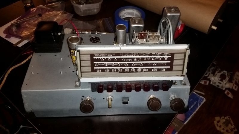 side shot  Another view showing string going over guides. That red wire and lamp holder will be redone and goes to the newer red wire lower in the shot. It then goes into the dial support hole you see above it there next to the tuning capacitor. 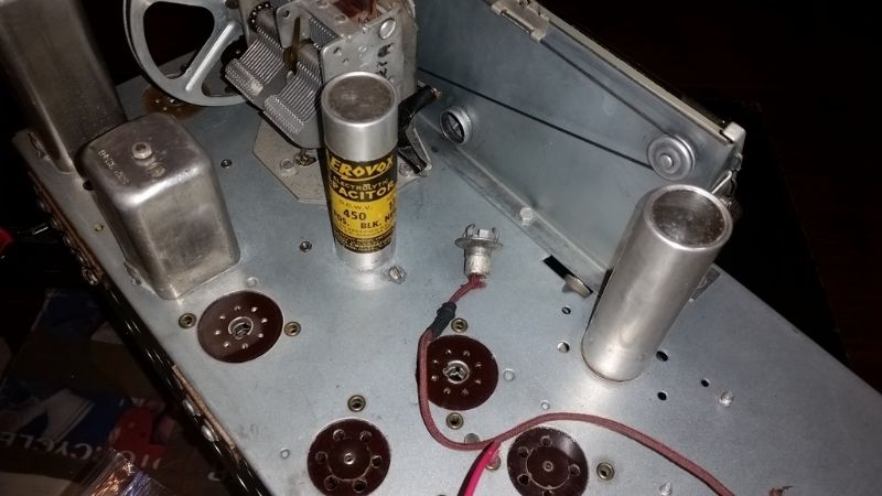 |
|
|
|
[#17]
That's "paper tape". The adhesive is mucilage, which requires being damped to make it sticky. It is a very appropriate for the era of the radio.
Keep going, Edisla, I love your threads. |
|
|
|
[#18]
So after removing the upper antenna one of the leads fell off.
Not a big deal really since the black wire was pretty much gone anyway. 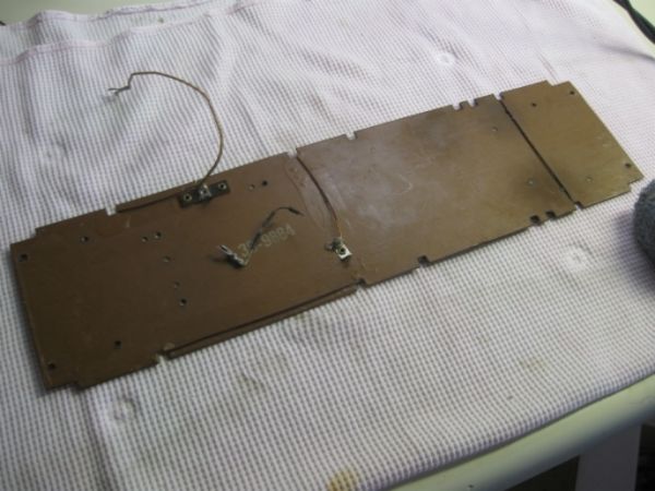 Here is the broken wire along w/ a new piece to take its place. 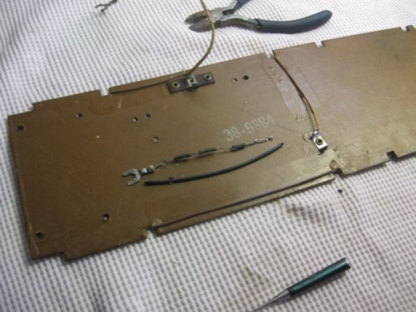 Here it is all fixed. 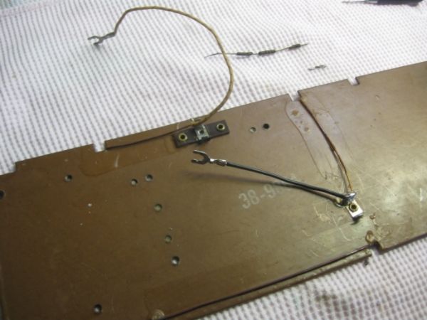 Now over to the dial lamp. The black shrink tubing or whatever it was is rock solid and has to go as well as the wire. 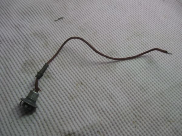 Here I have broken the black away from the wiring and have a scrap power cable I'll use some of the black insulation as the new black shrink tubing. 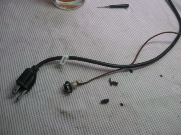 Here is the completely disassembled lamp unit. I had to break apart the rest of the black stuff out of the spring to free everything. 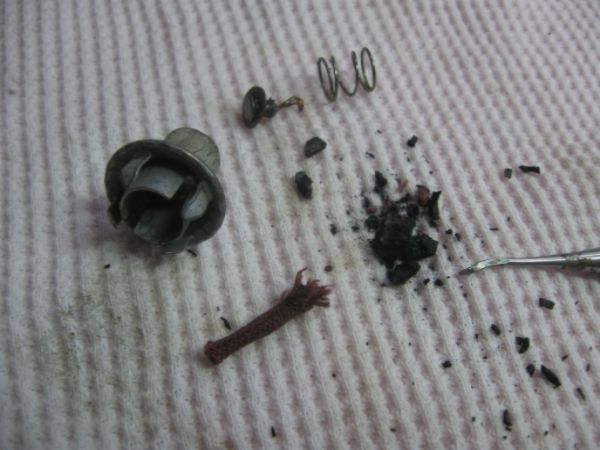 This is the assembly all back together w/o a bulb 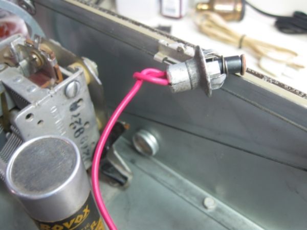 Bulb added. Bayonet style bulb.  Lamp unit set into the dial support. 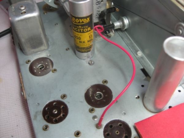 |
|
|
|
[#19]
Well I am at the point of tuning the radio but need to tackle something else first.
I did tune it a bit so the standard broadcast band was working so now I can take a look at the previously mentioned vibration in the speaker. All of the small tears in the cone were touched up with cone glue. I think the issue is that the voice coil is vibrating against the magnet rod at certain frequencies. I have removed the felt dust cover and am going to see what I can do to remedy the problem. 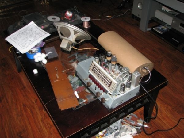 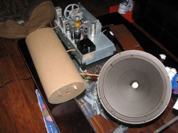 While I try and fix that issue lets move on to looking over the cabinet and getting some things done there. |
|
|
|
[#20]
First thing I wanted to do was get this nasty grill cloth off. They stapled this one down instead of gluing it. Probably a good thing really.
 There that is better :) 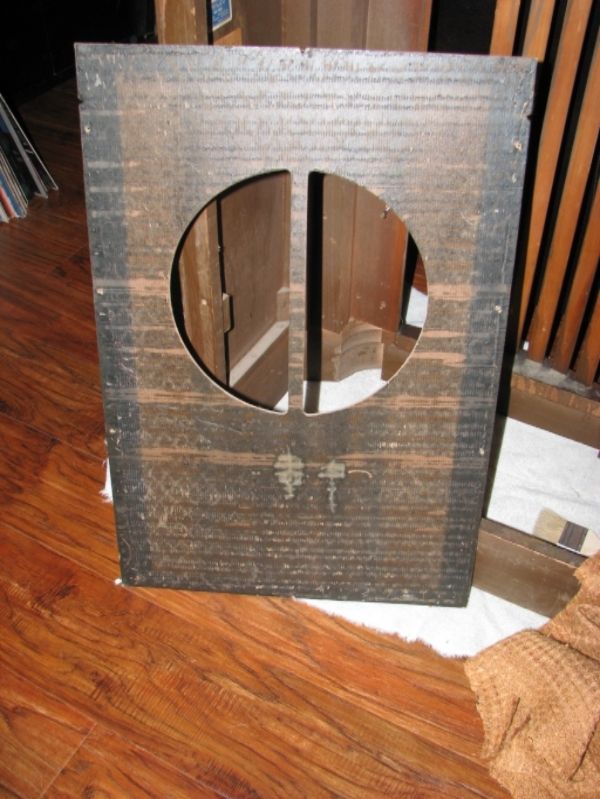 I'll need to research what is the proper cloth and order up something close to it if not exactly original. :) |
|
|
|
[#21]
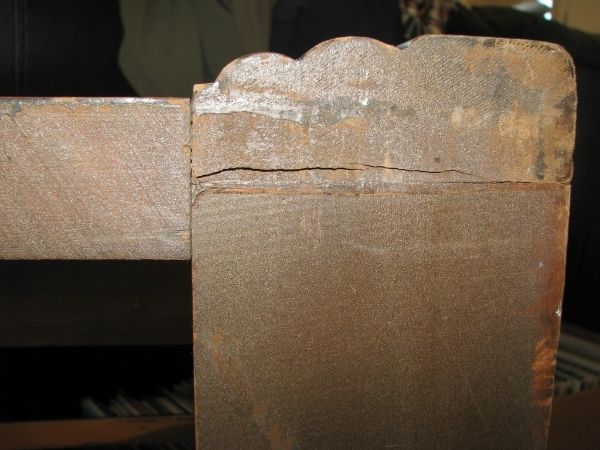
Here is the first busted section I'll be fixing. This is the back left bottom area.
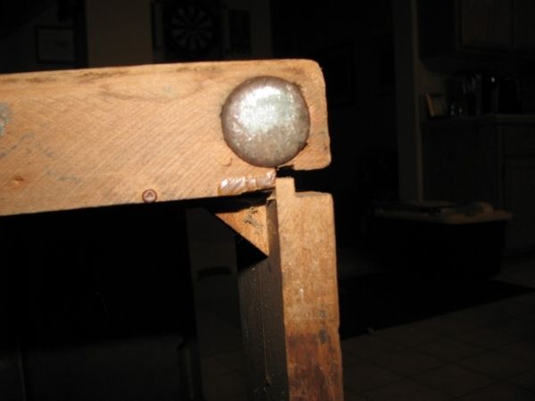  I did some dusting off of the area and some vacuuming to clear it up as much as I could before applying wood glue and clamping it down. "Clamping" or whatever ;) Here it is all glued up and "clamped" I'll see about filling in that missing chunk later. 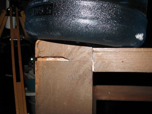 Clamped = 5 gallon water jug  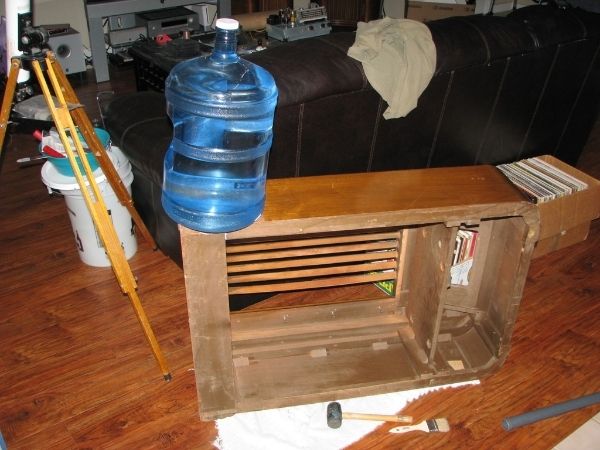 |
|
|
|
[#22]
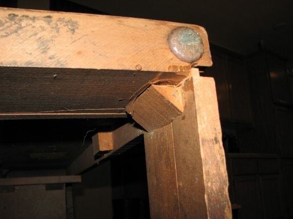
Working the lower right section in the same way as the left.
 Adding the 5 gallon water jug again to help squish it all back together the best I can 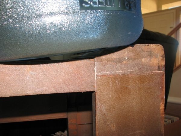 Yesterday was nice so I was able to get the cabinet outside in good lighting and really see what is going on. 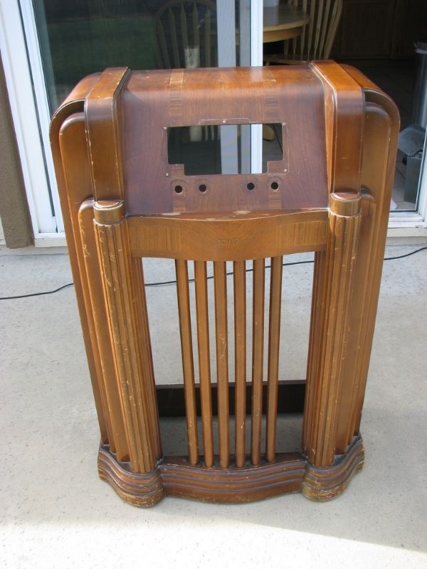 |
|
|
|
[#23]
Time to glue a few things down
This area of veneer is coming up and needs to be taken care of to the right is what is left of a factory sticker. I might replace but not sure yet.
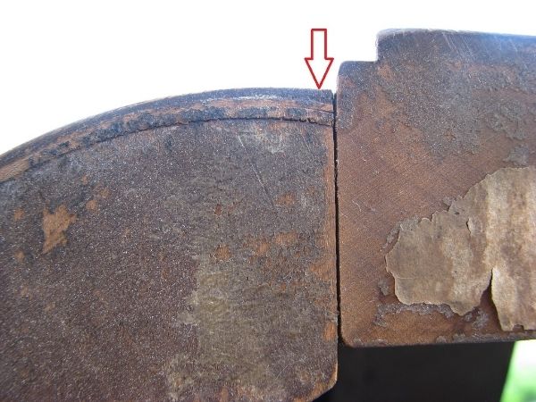 As well as this stretch 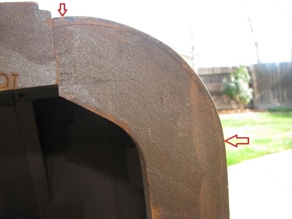 The end of this strip was moving a bit so I'll have to glue it down. I just dobbed the area w/ glue and didn't bother w/ a clamp. 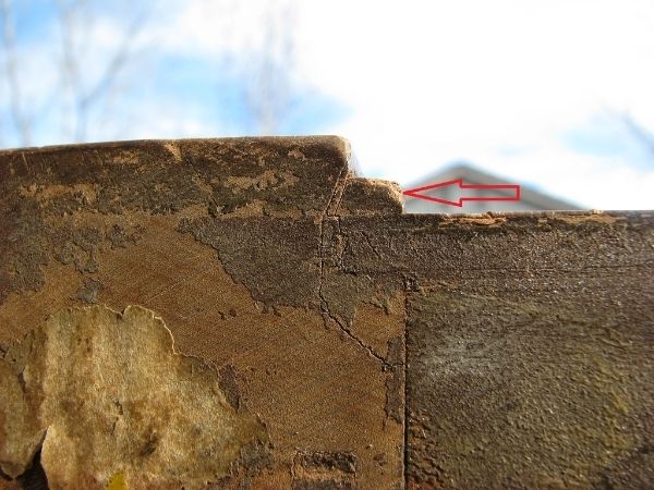 All glued and clamped down. I found a spot bottom left that needed some help. 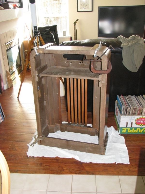 |
|
|
|
[#24]
This is one of the coolest thread I've seen in a long time

|
|
|
|
[#25]
Observations
Found some filler that needs to be removed 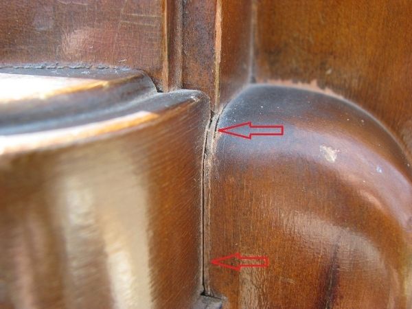 Here is the other side w/ most already gone except that one little chunk 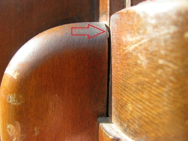 Some of the edges are toned darker than the rest of the cabinet and here is some added goodness, years of gunk build up. I scratched some away w/ my nail. Probably smoke and grease and who know what else 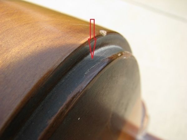 Here is the wire retainer that holds the wires from the antenna to the radio. This needs replacing. 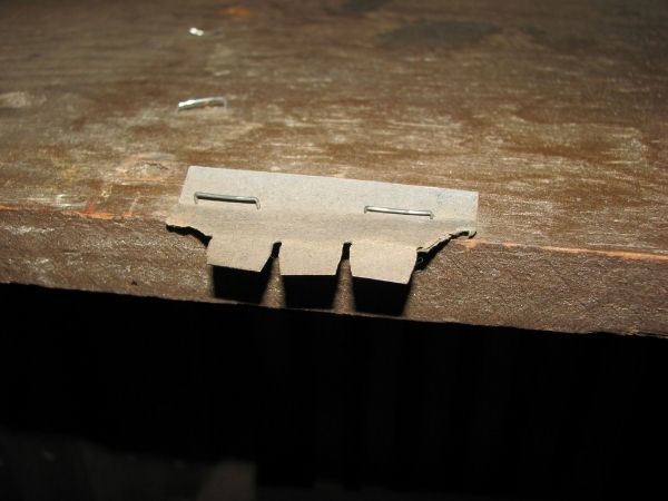 Here is the cardboard I'll be making a new one out of. Use what ya got 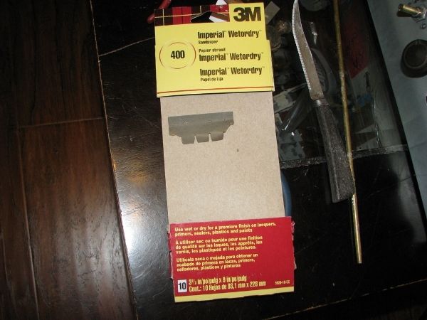 Stay tuned |
|
|
|
[#26]
Forgot this pic
I had not noticed these paint splatters until I took the cabinet out into the sunlight. One thing I figure is that if you can do all the cabinet work out in the sunlight and make it look good then it should look GREAT inside. When the cabinet is inside there are so many different ways that lighting hits it and it will hide many imperfections. This paint doesn't matter anyway since I'll be stripping the cabinet but it's fun to find these things as you go along. 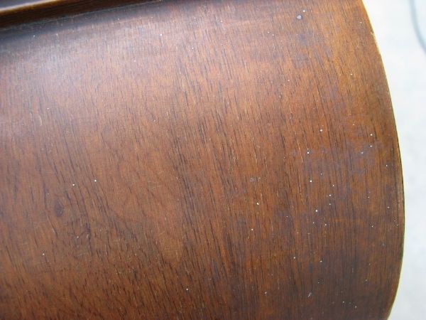 |
|
|
|
[#27]
Glued down the top front loose veneer this evening.
Here is a video of one of the sections showing it moving. Here is that same section lathered up w/ some thinned wood glue. I slapped it on and blew it into the cracks then wiped it clean. 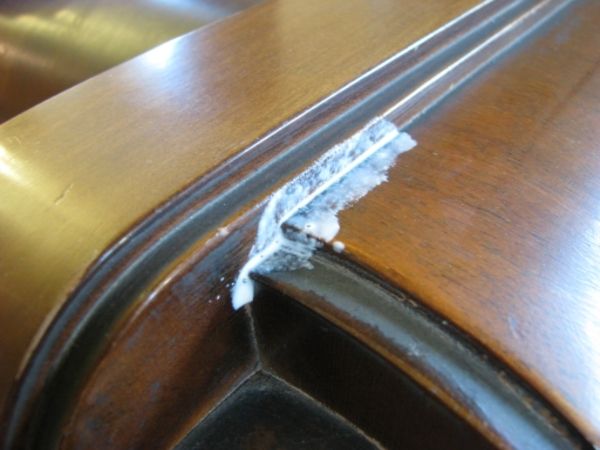 It didn't need much to hold it down so I used some painters tape 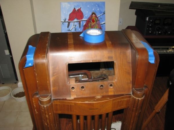 Even after you glues the loose veneer down it's always good to be careful when wiping the unit down. You don't want a rag or whatever you're using grabbing a piece of that veneer and ripping it right off |
|
|
|
[#28]
And here we go!
 |
|
|
|
[#29]
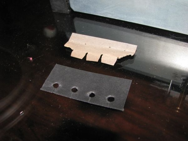
Stepping back a bit here.
This is the new wire holder for the antenna to chassis wires. I made it out of that cardboard from the sand paper packaging. punched some holes, added slits for wires, and then painted and clear coated it. This will get stapled to the cabinet when I put everything back together. No use in putting it on now and wrecking it while I redo the cabinet.
 |
|
|
|
[#30]
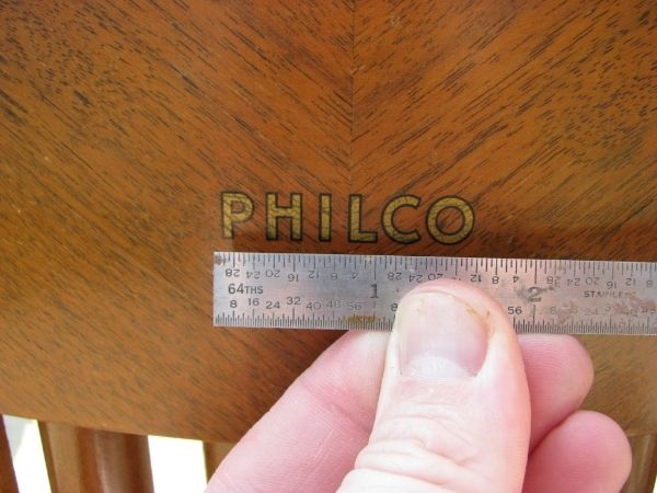
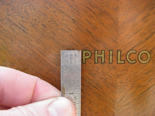
Rough measurement of the PHILCO decal even though I pretty much know what I need. Never hurts ;)
  Laying down some more stripper 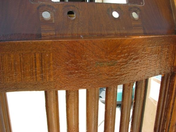 Bye bye decal :( 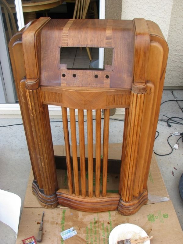 This is the gunk you strip off. Its probably many years worth of crap. Like snot from hell Well its down in there somewhere anyway. 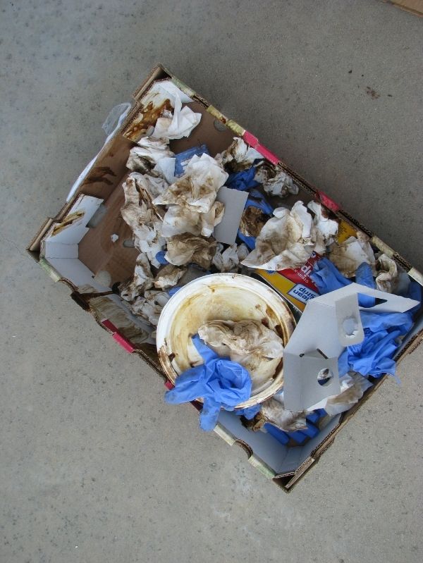 |
|
|
|
[#31]
So what is going on here is that I am using the stripper to remove all of the toner and coating off of the cabinet.
I go from the stripper to the lacquer thinner. Back and forth until I get it really clean. Once I get all the gunk off I'll use another stripping solution to get it really clean. You think you have it good until it all dries up and you see what is left behind and then you hit it again.
This will take a couple of passes. |
|
|
|
[#32]
So while I take a break from the cabinet lets go back to the speaker.
I mentioned before there was some distortion going on and I felt that it was somewhere in the speaker. I came to the conclusion that it had to be the voice coil winding or something close to it. I decided to do some major surgery and disassemble the entire speaker |
|
|
|
[#33]
I wonder if this part will be better off w/ video explanation rather than trying to do pics.
hmm |
|
|
|
[#34]
Quoted: I wonder if this part will be better off w/ video explanation rather than trying to do pics. hmm |
|
|
|
[#35]
Tag
|
|
|
|
[#36]
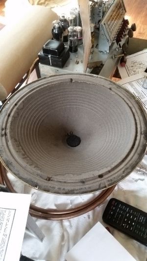
Pics to go with video coming soon
This is the speaker That ribbed deal in between the two green lines is the spider That is what I unglued first. The spider is what helps center and give springy action to the cone. 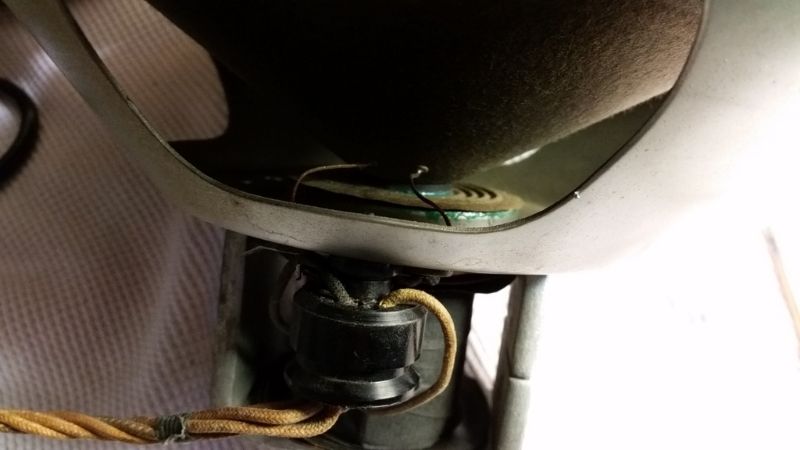 Here is the speaker w/ the cone removed I draw the rod way to far out in video but you can see it there. It is flush w/ the field coil. The voice coil sits about halfway down in there. 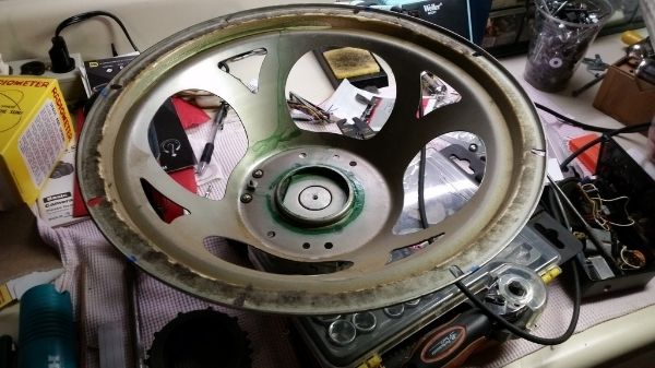 Here is the cone after removing I applied glue all around it to help secure the entire area. Was this the issue? Did this fix everything? At this point it's looking good but still not sure. 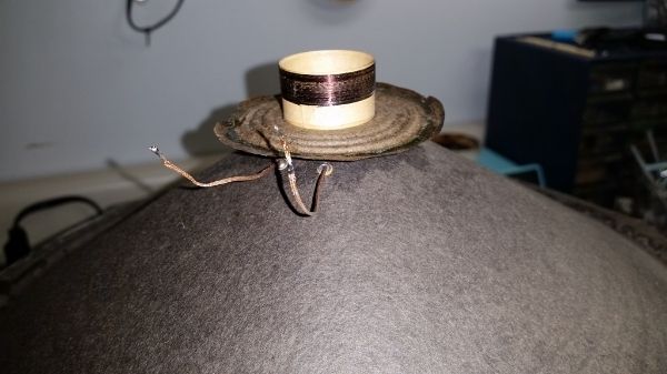 Here is how I setup the triangulated spacing of the voice coil while gluing the spider back down 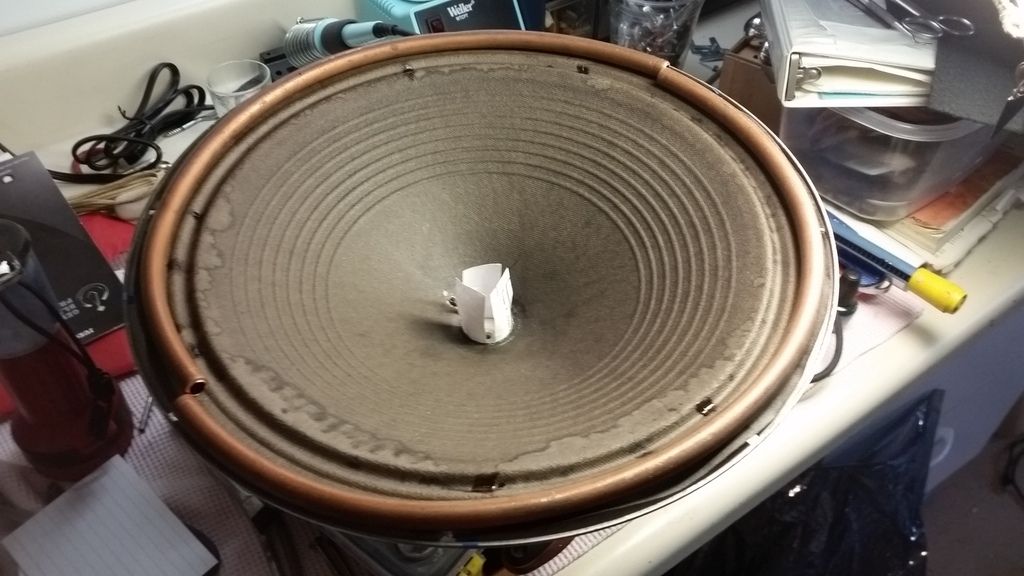 Now watch the video for a bit more explanation. I hope it makes some sense |
|
|
|
[#37]
Let me say this has been a bit on the slow side w/ this part.
Scares the shit outa me that I had to go here It will either work or not. |
|
|
|
[#38]
Here is the video.
I do draw the "rod" and then say its the voice coil but they are not one in the same. The voice coil slides along the rod. I do end up drawing the voice coil hard stock cylinder. If it doesn't make sense I can try and clarify. |
|
|
|
[#39]
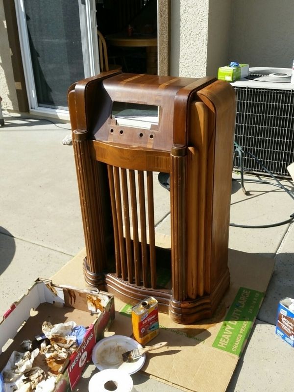
Here is where I ended up the other day.
Almost done stripping the cabinet down. 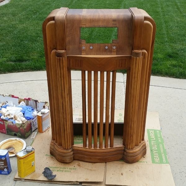 |
|
|
|
[#40]
So these new push buttons look great but are loose. If you push one in and then the next the one the pops back out shoots the button across the room
To fix I added a bit of tap to the button rod ends as shown here. 3rd button in you can see the tape I am about to wrap around the shaft. 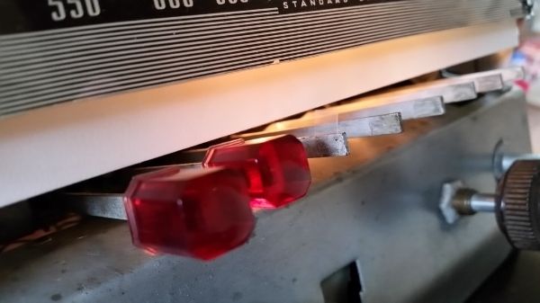 I also locked down the dial string to the needle. This keeps the needle from going out of alignment. I used some green nail polish for this. 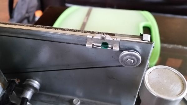 To top of the day I glued down the speaker cone and things are still sounding good. 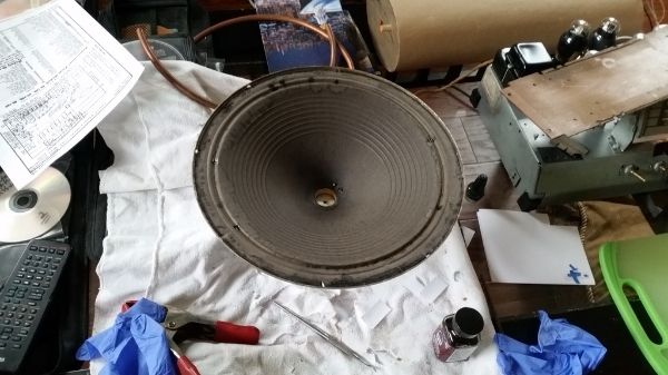 I'll check out the speaker tomorrow after it all dries up and if still good I'll put in a new voice coil dust cover. If this all works out I'll be amazed that I took apart an effen speaker and put it back together |
|
|
|
[#41]
Put on a new voice coil dust cover.
 Working on the alignment 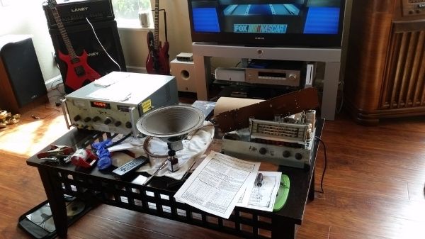 |
|
|
|
[#42]
yea, I think I need to just ship mine to you......LOL
speed |
|
|
|
[#43]
Quoted: yea, I think I need to just ship mine to you......LOL speed What was it you had again? |
|
|
|
[#44]
I would have to check to make sure, but I think they area, philco 40-180, a grunow 761, and an admiral 6t04. I have a sams for one of them, I believe its for the admiral. Now if I could just remember where I put it......LOL.
Speed |
|
|
|
[#45]
Quoted: I would have to check to make sure, but I think they area, philco 40-180, a grunow 761, and an admiral 6t04. I have a sams for one of them, I believe its for the admiral. Now if I could just remember where I put it......LOL. Speed Cool. 40-180 is very similar to this one. I have one over here in the corner ;) GET THOSE THINGS FIXED UP AND RUNNING!  Don't power up until you replace the caps and any other parts that don't look right. Also, add a fuse block on the power line. When ready to bring up do it slowly w/ a variac. |
|
|
|
[#46]
yep, I was noticing that they were very similar in the pics. I really want to get the grunow up and going, its pretty plain, but also kind of neat.
speed |
|
|
|
[#47]
Quoted: yep, I was noticing that they were very similar in the pics. I really want to get the grunow up and going, its pretty plain, but also kind of neat. speed DO IT! Ok back to the 40-190 ;) Well soon. Have not had good weather to mess w/ cabinet outside and am trying to tidy up the alingment. |
|
|
|
[#48]
Thanks! That will save me trying to find a sams for that one at least !
speed |
|
|
|
[#49]
Quoted: yep, I was noticing that they were very similar in the pics. I really want to get the grunow up and going, its pretty plain, but also kind of neat. speed All 3 of your radios are on that site under RESOURCES :) |
|
|
|
[#50]
Thanks again!
speed |
|
|
 Win a FREE Membership!
Sign up for the ARFCOM weekly newsletter and be entered to win a free ARFCOM membership. One new winner* is announced every week!
You will receive an email every Friday morning featuring the latest chatter from the hottest topics, breaking news surrounding legislation, as well as exclusive deals only available to ARFCOM email subscribers.

AR15.COM is the world's largest firearm community and is a gathering place for firearm enthusiasts of all types.
From hunters and military members, to competition shooters and general firearm enthusiasts, we welcome anyone who values and respects the way of the firearm.

Subscribe to our monthly Newsletter to receive firearm news, product discounts from your favorite Industry Partners, and more.
Copyright © 1996-2024 AR15.COM LLC. All Rights Reserved.
Any use of this content without express written consent is prohibited.
AR15.Com reserves the right to overwrite or replace any affiliate, commercial, or monetizable links, posted by users, with our own.


