|
Posted: 1/21/2012 8:56:53 AM EDT
I'm trying to organize my coaxes coming in from 3 antennas and manually route them to my 2 HF radios in the shack. After searching through the archives, I'm still unclear as to the correct, safest way to accomplish this. I think I'll need multiple antenna switches and perhaps a dummy load or 2 to protect the radios from me and each other. How are you guys doing this? Anyone have photos of their setups for reference?
Here's an overhead of my QTH with antennas marked up. 
Here's an example of what I think I need, but perhaps not as elaborate. (found this on the net here ––––> LINK) 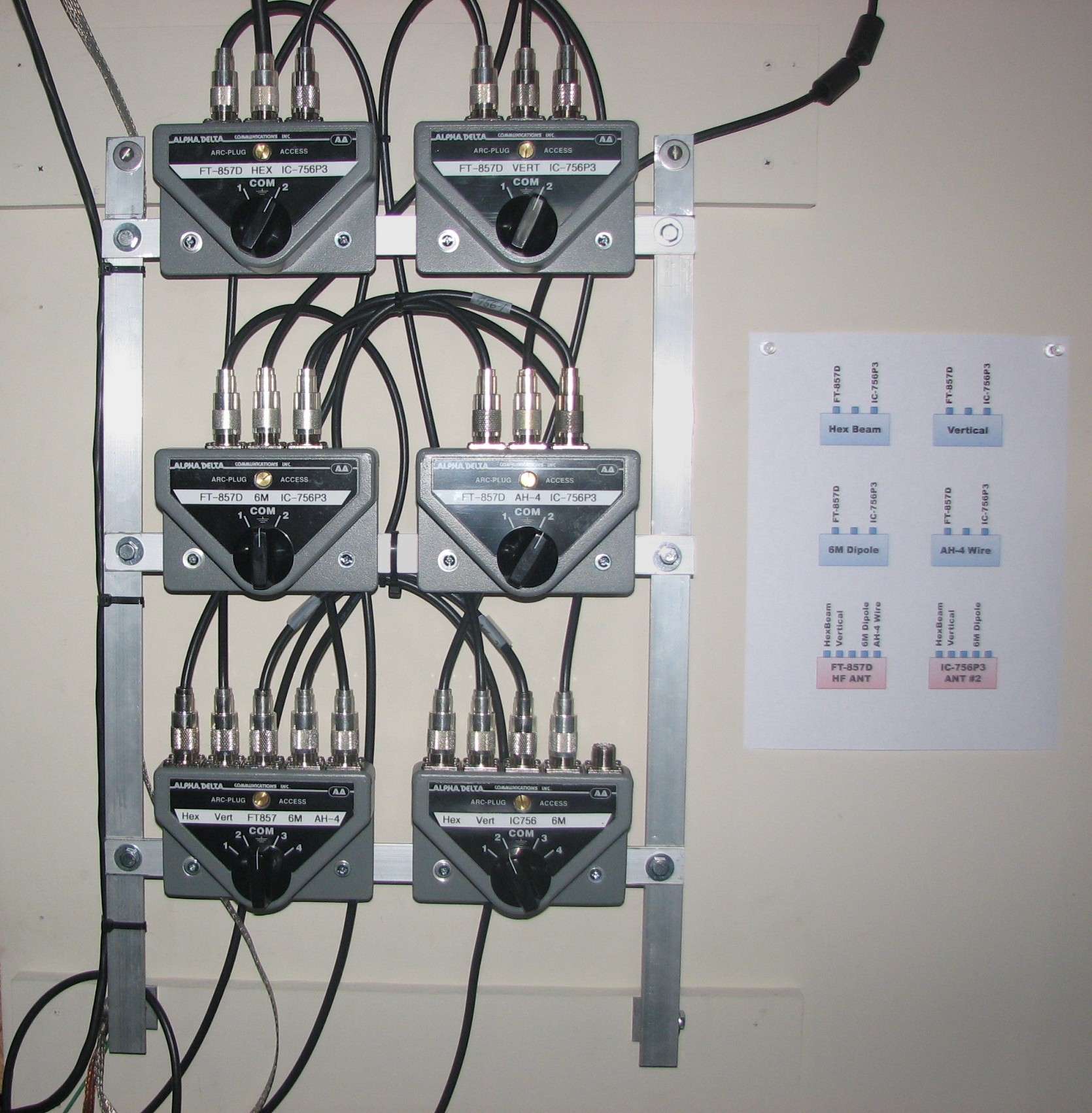
|
|
|
|
[#1]
I saw someone post a picture of a switch that they had made. They have it so when they switch one radio to an antenna the other radio is hooked into a dummy load. Am I comprehending your question? |
|
|
|
[#2]
As it gets more complex, some simply make a patch panel.
|
|
|
|
[#3]
Quoted:
As it gets more complex, some simply make a patch panel. I think this is the way to go. I have 2 rigs and 2 antennas, and the cost of doing it with switches v. getting some bulkhead connectors and a couple patch cords makes it a no-brainer. As your picture shows, it can turn into a huge maze quickly, whereas with a panel you just mark radio A and B, antenna and plug them in. If twirling the PL-259s is too much, you can use BNCs and adapters, a foot of RG-8X with BNCs isn't going to cost you much in terms of money or signal loss. I do own a switch, and have come close to smoking radios a couple times with it. |
|
|
|
[#4]
I too am planning on the patch panel plan of attack.
The only thing I am wondering is what kinda loss to expect from having extra barrel connectors? |
|
|
|
[#5]
Quoted:
I too am planning on the patch panel plan of attack. The only thing I am wondering is what kinda loss to expect from having extra barrel connectors? At 30MHz and below, it's a non-issue, the insertion loss barely registers on meters (it's about 0.1 dB). |
|
|
|
[#6]
Quoted:
Quoted:
I too am planning on the patch panel plan of attack. The only thing I am wondering is what kinda loss to expect from having extra barrel connectors? At 30MHz and below, it's a non-issue, the insertion loss barely registers on meters (it's about 0.1 dB). In that case I think a patch panel is the best. |
|
|
|
[#7]
Quoted:
Am I comprehending your question? Yep, that's what I was trying to say. Quoted:
Quoted:
As it gets more complex, some simply make a patch panel. I think this is the way to go. I do own a switch, and have come close to smoking radios a couple times with it. Quoted:
I too am planning on the patch panel plan of attack. This sounds a lot easier and bullet-proof to me. You guys just saved me from myself, again! Thanks for the help. |
|
|
|
[#8]
There is no way I could run the switch setup you posted a pic of.
I have two radios and 3 antennas at the moment on HF. The radios go into an A-B switch, with the common of that going to the common of an A-B-C-D switch. Those four connections go to the antennas and a dummy load. You can see it in the picture I posted on the grounding thread a while back. Very simple, just pick a radio and pick an antenna. The switches ground all unused connections, so your front-ends are safe. Still have to be careful. Make sure radio band, amp band, radio switch, antenna switch all match. Someday I'll have it all automated... |
|
|
|
[#9]
Quoted:
There is no way I could run the switch setup you posted a pic of. LOL...That is really complicated, isn't it? I need as KISS as possible, because I've been known to screw up every now and then! 
|
|
|
|
[#10]
I have some push-on PL-259's that make the patch panel really easy to implement. Although, I can't remember where I got them.
|
|
|
|
[#11]
Quoted:
I have some push-on PL-259's that make the patch panel really easy to implement. Although, I can't remember where I got them. Awesome suggestions. Looks like Buxcomm carries them. A quick google turned up a lot of push-on adapters. |
|
|
|
[#12]
BigDaddy, at our club station we have a box of 4-way and 2-way switches, three HF antennas (Moseley 20-15-10 Tribander, 80 m dipole, 80 m OCFD) and three HF rigs (IC-735, IC-751A, IC-718). We've tried coming up with a topology for switching each rig to each antenna. It is just too much, and too much chance of an accident. I'm about to scrap all that and go to a patch panel.
KISS, and a lot less crap on the wall. |
|
|
|
[#13]
But...a switch allows you to very quickly try a number of antennas to see which one is performing the best for a given signal or contact.
Get both Alternately put a 2x1 switch on each antenna so that each antenna is assigned to a different radio, then put a 3x1 on each radio. Worst thing that will happen then is that the radio will transmit into an open. ETA: or just get this. |
|
|
|
[#14]
This is what I would do......
Build one of these to switch the rigs, cost is less than 10 bucks 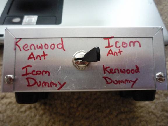

It will put the rig not switched to the antenna to the dummy load, From the antenna output on the rig switch you can have a standard 3 antenna switch to switch the antenna. The only thing it will not let you do is run both rigs at the same time, at least not with the switches. ETA: I have a schematic and a semi parts list if anyone wants one. |
|
|
|
[#15]
Quoted: THATS who did it!!!!!!!This is what I would do...... Build one of these to switch the rigs, cost is less than 10 bucks http://www.qsl.net/n6dlh/antenna_switch_files/image014.jpg http://www.qsl.net/n6dlh/antenna_switch_files/image016.jpg It will put the rig not switched to the antenna to the dummy load, From the antenna output on the rig switch you can have a standard 3 antenna switch to switch the antenna. The only thing it will not let you do is run both rigs at the same time, at least not with the switches. Stan, where is your write up on that? |
|
|
|
[#16]
I will send it you in in a PM.
|
|
|
|
[#17]
Quoted: Sounds good.I will send it you in in a PM. |
|
|
|
[#18]
Quoted:
There is no way I could run the switch setup you posted a pic of. Then think about a bunch of club members trying to do this, too. We were trying to lay it out with switches, then said, "We will need to laminate a diagram to put up here so anyone other than just you and me can run this." And I'm sure someone would look at the diagram and think, "What the hell is this? Portrait of the Spaghetti Monster?" |
|
|
|
[#19]
OK what about the MFJ 1700C? 6 radios, 6 antennas in any combination. Also has a gas discharge arrestor built in.
Just a thought! Sarge |
|
|
|
[#20]
That's a neat looking setup, but a lot of money. if you get a third adio then what? (BD you sure have a lot of stuff in your yard) |
|
|
|
[#21]
It is so much easier with my amplifier having 2 radio ports and 4 antennas.
|
|
|
|
[#22]
Quoted:
This is what I would do...... Build one of these to switch the rigs, cost is less than 10 bucks The problem with that is that standard switches like that are not rated for RF or sufficiently high voltages, and you have little isolation between the signal paths so tons of leakage from a transmitter into the other rigs receiver. |
|
|
|
[#23]
Quoted:
Quoted:
This is what I would do...... Build one of these to switch the rigs, cost is less than 10 bucks The problem with that is that standard switches like that are not rated for RF or sufficiently high voltages, and you have little isolation between the signal paths so tons of leakage from a transmitter into the other rigs receiver. Prolly not too much of a problem with 100 watts belo 28 mhz... There's a lot of possibilities for switches, there are some wide spaced ceramic rotaries that aren't too costly. I need to break one open and look ––but even 3-way [SPDT] 110 vac wall switches may have possibilities at HF for having decent isolation at moderate power. You might use them in pairs.so as to implement a more complex dummy load safety function. |
|
|
|
[#24]
Homemade 'coax' relays are another possibilty. Lot's of convenience.
At HF lead lengths aren't real critical and cheap ebay power relays, especially if they lend themselves to puttting a copper foil ground plane near and about the contacts and wire would very likely work great! I could sweep a couple different kinds if there's LOTs of interest... |
|
|
|
[#25]
Quoted:
(BD you sure have a lot of stuff in your yard) All the antennas... or the swing set / Generator Shed, trampoline, basketball court / patio, Station Grounding / Lightning Protection stuff? 

|
|
|
|
[#26]
The equasion is a ton easier if you dont want to use both radios with the choice of 3 antennas at the same time. If you can live with selecting one antenna to run either radio...it's fairly simple. 3 into 1(switch A) - 1 out to 2(switch B). Antenna switches can work both ways, combiner or splitter.
I have 2 antennas that can feed either of 2 radios. One antenna, one radio. If I want to switch to a different antenna...I flip the 'A' switch. If I want to change radios....I flip the 'B' switch. If I wanted to select a different antenna for each radio for simultaneous use....the equasion become more complex. Most times, I'm running HF on one radio, and 2 meters on the other, so I'm only gonna change the antenna switch 'A' on the HF set to select the prefered antenna. |
|
|
|
[#27]
Quoted:
All the antennas... or the swing set / Generator Shed, trampoline, basketball court / patio, Station Grounding / Lightning Protection stuff? Hey I didn't say it was too much, just noticing a bit of contrast to the neighbors'. But I keep a lot more stuff in my yard than my neighbors too. I had one complain once, I told him he would get used to it. There are no such deed restrictions, and the place in Oregon has several very visible antennas too. Nobody has ever complained verbally about them, but there is a bullet hole through my 220 Isopole! |
|
|
|
[#28]
Quoted:
Quoted:
Quoted:
This is what I would do...... Build one of these to switch the rigs, cost is less than 10 bucks The problem with that is that standard switches like that are not rated for RF or sufficiently high voltages, and you have little isolation between the signal paths so tons of leakage from a transmitter into the other rigs receiver. Prolly not too much of a problem with 100 watts belo 28 mhz... There's a lot of possibilities for switches, there are some wide spaced ceramic rotaries that aren't too costly. I need to break one open and look ––but even 3-way [SPDT] 110 vac wall switches may have possibilities at HF for having decent isolation at moderate power. You might use them in pairs.so as to implement a more complex dummy load safety function. I broke one open, the contact isolation was larger than most cheap antenna switches, and was larger than most relay contact isolation on TR/RX relays, I measured around .500 inch. The biggest issue when I did the research was contact and switch impedance. Some switches that are not RF rated may add impedance to the transmission line(This is what I was reading on some of the forums), I did put the switch in line with the dummy load and an SWR meter between the switch and the radio, impedance did not appear to be affected. That was about the best test I could do for impedance with the equipment I have. The switch is rated for 250v at 6 amps, so it is fairly heavy duty. I do not think leakage is an issue, my computer monitor seems to be affected by any near fields, and will flicker. The box sits next to it, and the monitor never budges. Of course at VHF/UHF I am sure it would. I can also use the multimeter on the dummy load while transmitting on the antenna, the multimeter will read around 1mv while transmitting. Same thing then measuring the SO-239 for the other rig directly with a multimeter, most of that is more than likely a little common mode coming back from the SGC tuner. Not scientific testing, but it seems to work fine. After reading articles on other similar switches being used, and of course the old knife switches on novice rigs I decided that the only way to be sure is to try it, and I am happy with the results. The last thing you want to do is make a mistake on something like that, it gets expensive quick. And I have already made the mistake of forgetting the switch was on the wrong setting, but instead of transmitting into an open transmission line, I was warming the oil in the dummy load. I like making things idiot proof. |
|
|
|
[#29]
I too was curious and did some testing using a SPST wall light switch, the cheapest $1.50 version and also a cheap SPDT wall switch [3-way].
Test instrument is an HP 8711C network analyzer. I'll try to format the results... Test frequencies in mhz were: 1 .... 5 ..... 15 .... 30 .... 60 Isolation in db SPST switch 80 ... 60 ... 50 ... 45 ... 40 Return loss in db SPST switch 32 ... 35 ... 25 ... 22 ... 20 Isolation in db for the SPDT switch between the poles [not the operating pole] 55 ... 43 ... 40 ... 38 ... 30 Isolation between the common pole and one of the poles 65 ... 57 ... 44 ... 40 ... 31 Test was conducted with the switch on a piece of PC material used as a ground plane with the test coax grounded close to the terminal being measured. With good wiring practice and a piece of PC bd material as a shield and ground plane, these switches should work to 6 meters and with degraded performance to 100 mc. So, for example, if you had 2 antennas and two radios, putting two SPDT switches side by side and wiring them with with opposite poles cross connected as an "X" and connecting one radio to each of the operating points, it may be possible to toggle the radios to opposite antennas by toggling the pair of switches. If this makes any sense. I wouldn't run to high power until you have some experience with this. |
|
|
|
[#30]
Vanco makes some nice bulk cable plates.
http://www.vanco1.com/catalog/148/Bulk-Cable-Wall-Plates You can also find recessed boxes made for going behind wall hung flat screen TV's. Trying to decide how to handle the same issue. Either bring the cables in through one of those Vanco covers with a rework duplex box or build a patch panel. It would be nice if it were recessed at least to the depth of the SO239's, I'm leaning that way for the moment if I can figure out a way to make it work in the wall. I'd like an aluminum panel that will also serve as a SPG for everything else but I'm a real stickler for neat & tidy. Off to find a 4 outlet recessed rework box......... ETA this might work: http://deepsurplus.com/Network-Structured-Wiring/Dry-Wall-Brackets/4-Gang-Recessed-Mounting-Bracket toss the outlet cover and replace it with an aluminum plate.   |
|
|
|
[#31]
That looks nice, but why does the wall have to be orange?
Posted Via AR15.Com Mobile |
|
|
|
[#32]
Quoted:
That looks nice, but why does the wall have to be orange? Posted Via AR15.Com Mobile Its an Emcomm wall. Duh.
Also, I used to volunteer at the Battleship NJ. The hamshack there has 3 radios and 4 or 5 antennas. We just used a patch panel with quick disconnect connectors. |
|
|
|
[#33]
W1AW uses the patch panel approach (on the left of the pic). The transmitters in the rack are for "broadcast" (code practice, bulletins, etc.), but the patch panels connect up the transceivers in the various studios.. It works very well.

|
|
|
|
[#34]
Quoted:
Quoted:
That looks nice, but why does the wall have to be orange? Posted Via AR15.Com Mobile Its an Emcomm wall. Duh.
Also, I used to volunteer at the Battleship NJ. The hamshack there has 3 radios and 4 or 5 antennas. We just used a patch panel with quick disconnect connectors. I snapped a couple of pics for that too. You know, in case this thread were to happen. 

|
|
|
|
[#35]
I found just the thing to tidy all this up all in one box.
Some simple digital logic and ptt inhibits and it would be idiot proof. You may say too much $$$ but by the time you buy switches and make or buy patch cables I would bet this would cost less. http://www.microham-usa.com/Products/Antenna_Switches/double%20six%20switch.html look on page 9 of the manual http://www.microham.com/Downloads/micro_DOUBLE_SIX_SWITCH_English_Manual.pdf 
ETA After looking further operator error fault is built in. 
A special method of connecting relay power is employed which prevents switching both radio ports to the same antenna. Additional signal relays ensure maximum separation even with a drive control fault. Without this protection,the isolation between radio ports would decrease by half. For example, with an output power of 1000W (60 dBm), in the event of a control fault, the other radio port would would see 25 dBm (0.3 W) instead of -10dBm = 0.0001W. |
|
|
|
[#36]
Quoted:
Quoted:
Quoted:
As it gets more complex, some simply make a patch panel. I think this is the way to go. I do own a switch, and have come close to smoking radios a couple times with it. Quoted:
I too am planning on the patch panel plan of attack. This sounds a lot easier and bullet-proof to me. You guys just saved me from myself, again! Thanks for the help. I did some work on the shack today and installed a simple patch panel for my three antennas and two HF radios. 

|
|
|
|
[#37]
I was going to vote patch panel too...

Because they are soo cool.. You beat me to the punch BD. |
|
|
 Win a FREE Membership!
Sign up for the ARFCOM weekly newsletter and be entered to win a free ARFCOM membership. One new winner* is announced every week!
You will receive an email every Friday morning featuring the latest chatter from the hottest topics, breaking news surrounding legislation, as well as exclusive deals only available to ARFCOM email subscribers.

AR15.COM is the world's largest firearm community and is a gathering place for firearm enthusiasts of all types.
From hunters and military members, to competition shooters and general firearm enthusiasts, we welcome anyone who values and respects the way of the firearm.

Subscribe to our monthly Newsletter to receive firearm news, product discounts from your favorite Industry Partners, and more.
Copyright © 1996-2024 AR15.COM LLC. All Rights Reserved.
Any use of this content without express written consent is prohibited.
AR15.Com reserves the right to overwrite or replace any affiliate, commercial, or monetizable links, posted by users, with our own.


