|
Posted: 9/13/2014 4:44:55 PM EDT
I originally posted this question in the Uppers and Barrel's Forum but on further thought it probably belongs here.
I purchased a USGI field gauge. When the bolt is inserted into chamber I am assuming that if the lugs are not able to rotate into a "locked" position then the chamber is good to go? It came with this spec sheet: 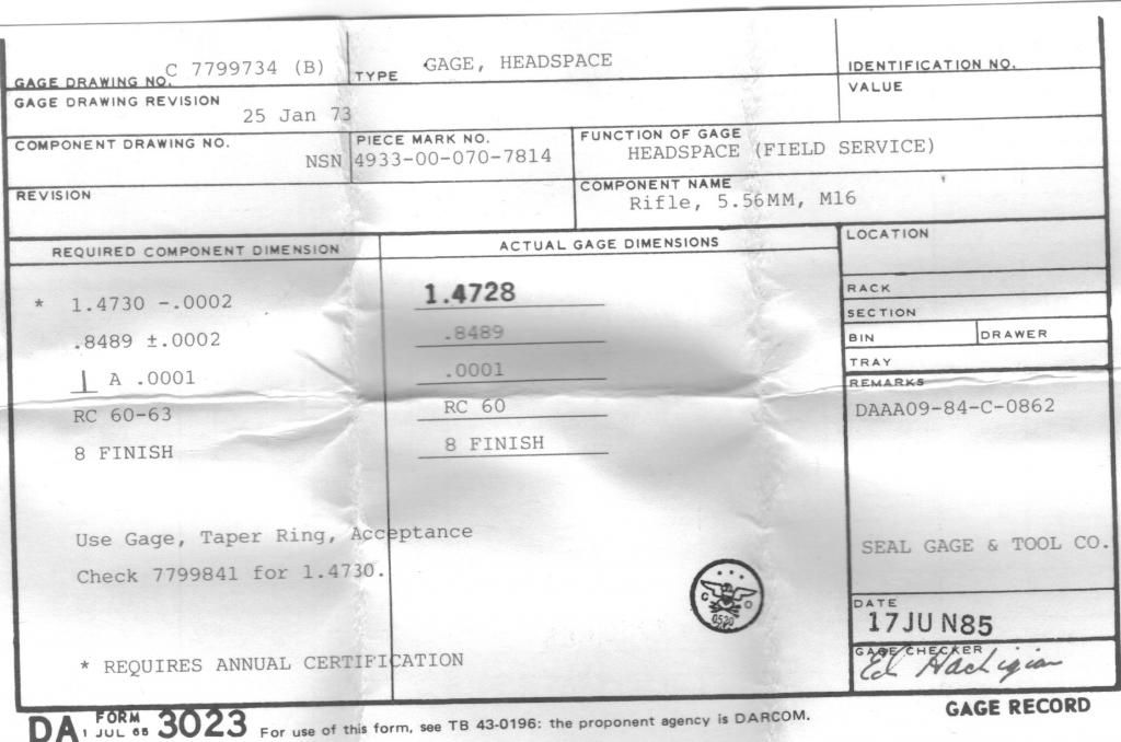 </a>" /> </a>" />
|
|
|
|
[#1]
The USGI Field Gauge's purpose is for unit armorers to do yearly checks, as stated in TM 9-1005-319-23&P, for rifles or carbines to make sure headspace has not become excessive. The maximum headspace before the barrel is officially used up in a M16/M4/AR15 is 1.4736". Which by the paperwork, your USGI Field is 0.0008" shy of this. Which 8/10,000th's of an inch is infinitesimally small.
If you want to know the actual measurement for you weapon's headspace it is rather easy to do using this gauge if are are able to get the measurement from the end of the gauge (side facing the bolt-face) to the inside edge of the barrel extension's lugs. Then the measurement from the bolt's bolt-face to the inside edge of the bolt' s lugs. Add the measurement you found for the barrel to the measurement listed on the paper, and then subtract this from the measurement you found for the bolt. As an example, looking at the blueprints below, if you subtract the barrel measurement 1.6206" from the bolt measurement 0.156", the headspace would equal 1.4646" This is the minimum headspace (1.4646") as listed in the milspecs for a new barrel that has been high pressure tested (HPT). As listed in TM 9-1005-319-23&P when checking headspace. Separate the upper from the lower. Remove the bcg, and insert the field gauge into the chamber. Reinsert the charging handle and bcg, with the charging handle's latch secured, push the bcg towards the field gauge. In order to pass the headspace check, the rear of the carrier should be sticking out past the upper receiver; and if the rear of the carrier is flush with the upper receiver, it fails the check. Which you would try rechecking the headspace using another bolt first before swapping for another barrel to check again with the original bolt. If it still fails, then you check the new barrel once more with a new bolt. 

|
|
|
|
[#2]
Quoted:
The USGI Field Gauge's purpose is for unit armorers to do yearly checks, as stated in TM 9-1005-319-23&P, for rifles or carbines to make sure headspace has not become excessive. The maximum headspace before the barrel is officially used up in a M16/M4/AR15 is 1.4736". Which by the paperwork, your USGI Field is 0.0008" shy of this. Which 8/10,000th's of an inch is infinitesimally small. If you want to know the actual measurement for you weapon's headspace it is rather easy to do using this gauge if are are able to get the measurement from the end of the gauge (side facing the bolt-face) to the inside edge of the barrel extension's lugs. Then the measurement from the bolt's bolt-face to the inside edge of the bolt' s lugs. Add the measurement you found for the barrel to the measurement listed on the paper, and then subtract this from the measurement you found for the bolt. As an example, looking at the blueprints below, if you subtract the barrel measurement 1.6206" from the bolt measurement 0.156", the headspace would equal 1.4646" This is the minimum headspace (1.4646") as listed in the milspecs for a new barrel that has been high pressure tested (HPT). As listed in TM 9-1005-319-23&P when checking headspace. Separate the upper from the lower. Remove the bcg, and insert the field gauge into the chamber. Reinsert the charging handle and bcg, with the charging handle's latch secured, push the bcg towards the field gauge. In order to pass the headspace check, the rear of the carrier should be sticking out past the upper receiver; and if the rear of the carrier is flush with the upper receiver, it fails the check. Which you would try rechecking the headspace using another bolt first before swapping for another barrel to check again with the original bolt. If it still fails, then you check the new barrel once more with a new bolt. http://i1286.photobucket.com/albums/a601/AVIDavid1982/headspaceboltdimensionalinspeciton_zpsfec02fd8.png http://i1286.photobucket.com/albums/a601/AVIDavid1982/headspacechamberdimensionalinspection_zps6af43d67.png That's all great technical info and I appreciate the detail and if I read it correctly the bolt lugs should not be able to turn in the chamber to lock in position. Is this correct?? This is the gauge: 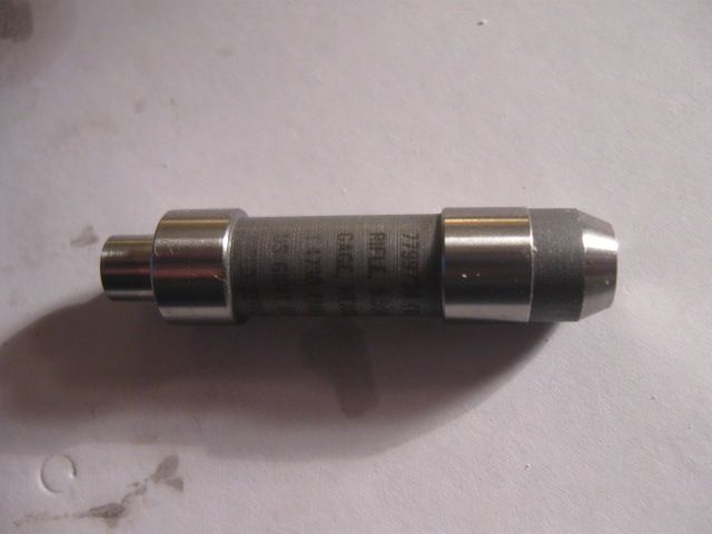 " /> " />
|
|
|
|
[#3]
This is how to use the gage as per the instructions of TM 9-1005-319-23&P. What I was referring to, I highlighted in red.
Pages 0015-25 k 0015-26 of TM 9-1005-319-23&P Figure 34. Insertion of Headspace Gage. 5. Assemble charging handle assembly (32), bolt assembly (33), and key and bolt carrier assembly (34) into upper receiver assembly (11). 6. Insert headspace gage PN 7799734 (35) in chamber. Figure 35. Checking Headspace. NOTE: For the purpose of this test "light finger pressure" is defined as 8 1/2 to 8 3/4 pounds. 7. Check headspace by pressing key and bolt carrier assembly (34) and charging handle assembly (32) forward using light finger pressure. 8. Bolt should not rotate to locked position. Key and bolt carrier assembly (34) must protrude from rear of upper receiver assembly (11) for proper headspace. Figure 36. Use of Weights in Headspace Check. 9. If the test fails using finger pressure, remove the gage and perform the test again as follows. With the muzzle down, stack 8 1/2 to 8 3/4 pounds of trigger weights (36) on a locally fabricated spacer/weight (37) on key and bolt carrier assembly (34). Insert headspace gage (35) and test per above instructions. 10. Remove trigger weights (36), spacer/weight (37), key and bolt carrier assembly (34), charging handle (32), and headspace gage (35). 11. If excessive headspace, first replace bolt assembly and then recheck. If headspace is not corrected, replace barrel assembly; then recheck with the original bolt to determine if the bolt is still good or if the bolt should be replaced also. 12. Remove key and bolt carrier assembly, bolt assembly, charging handle assembly, and headspace gage. 13. Reassemble weapon; refer to TM 9-1005-319-10. |
|
|
|
[#4]
Quoted:
This is how to use the gage as per the instructions of TM 9-1005-319-23&P. What I was referring to, I highlighted in red. Pages 0015-25 k 0015-26 of TM 9-1005-319-23&P Figure 34. Insertion of Headspace Gage. 5. Assemble charging handle assembly (32), bolt assembly (33), and key and bolt carrier assembly (34) into upper receiver assembly (11). 6. Insert headspace gage PN 7799734 (35) in chamber. Figure 35. Checking Headspace. NOTE: For the purpose of this test "light finger pressure" is defined as 8 1/2 to 8 3/4 pounds. 7. Check headspace by pressing key and bolt carrier assembly (34) and charging handle assembly (32) forward using light finger pressure. 8. Bolt should not rotate to locked position. Key and bolt carrier assembly (34) must protrude from rear of upper receiver assembly (11) for proper headspace. Figure 36. Use of Weights in Headspace Check. 9. If the test fails using finger pressure, remove the gage and perform the test again as follows. With the muzzle down, stack 8 1/2 to 8 3/4 pounds of trigger weights (36) on a locally fabricated spacer/weight (37) on key and bolt carrier assembly (34). Insert headspace gage (35) and test per above instructions. 10. Remove trigger weights (36), spacer/weight (37), key and bolt carrier assembly (34), charging handle (32), and headspace gage (35). 11. If excessive headspace, first replace bolt assembly and then recheck. If headspace is not corrected, replace barrel assembly; then recheck with the original bolt to determine if the bolt is still good or if the bolt should be replaced also. 12. Remove key and bolt carrier assembly, bolt assembly, charging handle assembly, and headspace gage. 13. Reassemble weapon; refer to TM 9-1005-319-10. Great...exactly what I was looking for. Thanx very much. |
|
|
|
[#5]
Quoted:
That's all great technical info and I appreciate the detail and if I read it correctly the bolt lugs should not be able to turn in the chamber to lock in position. Is this correct?? Yes. As noted earlier, the FIELD gauge is used to see if the headspace is excessive (too deep for that bolt). If you CANNOT lock the bolt (if the bolt can't turn in the barrel extension's locking lugs) on the FIELD gauge,then headspace is good to go. The Rules: Bolt does NOT close with GO gauge: BAD Bolt closes with GO gauge: GOOD Bolt closes with NO GO or FIELD gauge: BAD Bolt does NOT close with NO GO or FIELD gauge: GOOD |
|
|
|
[#6]
Quoted:
Yes. As noted earlier, the FIELD gauge is used to see if the headspace is excessive (too deep for that bolt). If you CANNOT lock the bolt (if the bolt can't turn in the barrel extension's locking lugs) on the FIELD gauge,then headspace is good to go. The Rules: Bolt does NOT close with GO gauge: BAD Bolt closes with GO gauge: GOOD Bolt closes with NO GO or FIELD gauge: BAD Bolt does NOT close with NO GO or FIELD gauge: GOOD Quoted:
Quoted:
That's all great technical info and I appreciate the detail and if I read it correctly the bolt lugs should not be able to turn in the chamber to lock in position. Is this correct?? Yes. As noted earlier, the FIELD gauge is used to see if the headspace is excessive (too deep for that bolt). If you CANNOT lock the bolt (if the bolt can't turn in the barrel extension's locking lugs) on the FIELD gauge,then headspace is good to go. The Rules: Bolt does NOT close with GO gauge: BAD Bolt closes with GO gauge: GOOD Bolt closes with NO GO or FIELD gauge: BAD Bolt does NOT close with NO GO or FIELD gauge: GOOD You say too deep for that bolt. I'm not understanding what you are referring to and what you mean saying too deep? Apologies for the ignorance. 
|
|
|
|
[#7]
Quoted:
[You say too deep for that bolt. I'm not understanding what you are referring to and what you mean saying too deep? Apologies for the ignorance. Headspace is essentially the interaction between the specific chamber and the specific bolt you're testing it with. Headspace is defined as the distance between the bolt face and the headspace point in the chamber (the "datum circle," which is the point where the shoulder is a specified diameter). Another bolt may be just a little different, and make that distance just short enough to not allow that bolt to close on the FIELD gauge. |
|
|
|
[#8]
Quoted:
Headspace is essentially the interaction between the specific chamber and the specific bolt you're testing it with. Headspace is defined as the distance between the bolt face and the headspace point in the chamber (the "datum circle," which is the point where the shoulder is a specified diameter). Another bolt may be just a little different, and make that distance just short enough to not allow that bolt to close on the FIELD gauge. Quoted:
Quoted:
[You say too deep for that bolt. I'm not understanding what you are referring to and what you mean saying too deep? Apologies for the ignorance. Headspace is essentially the interaction between the specific chamber and the specific bolt you're testing it with. Headspace is defined as the distance between the bolt face and the headspace point in the chamber (the "datum circle," which is the point where the shoulder is a specified diameter). Another bolt may be just a little different, and make that distance just short enough to not allow that bolt to close on the FIELD gauge. I see...I thought you were possibly referring to the gauge I posted a pic of.....That it was not the correct one. |
|
|
|
[#9]
Quoted:
I see...I thought you were possibly referring to the gauge I posted a pic of.....That it was not the correct one. Quoted:
Quoted:
Quoted:
[You say too deep for that bolt. I'm not understanding what you are referring to and what you mean saying too deep? Apologies for the ignorance. Headspace is essentially the interaction between the specific chamber and the specific bolt you're testing it with. Headspace is defined as the distance between the bolt face and the headspace point in the chamber (the "datum circle," which is the point where the shoulder is a specified diameter). Another bolt may be just a little different, and make that distance just short enough to not allow that bolt to close on the FIELD gauge. I see...I thought you were possibly referring to the gauge I posted a pic of.....That it was not the correct one. No, I was referring to using headspace gauges in general. The gauge you posted a picture of is a great gauge, and you don't need to take anything off of your bolt to use it accurately, which is a plus. |
|
|
 Win a FREE Membership!
Sign up for the ARFCOM weekly newsletter and be entered to win a free ARFCOM membership. One new winner* is announced every week!
You will receive an email every Friday morning featuring the latest chatter from the hottest topics, breaking news surrounding legislation, as well as exclusive deals only available to ARFCOM email subscribers.

AR15.COM is the world's largest firearm community and is a gathering place for firearm enthusiasts of all types.
From hunters and military members, to competition shooters and general firearm enthusiasts, we welcome anyone who values and respects the way of the firearm.

Subscribe to our monthly Newsletter to receive firearm news, product discounts from your favorite Industry Partners, and more.
Copyright © 1996-2024 AR15.COM LLC. All Rights Reserved.
Any use of this content without express written consent is prohibited.
AR15.Com reserves the right to overwrite or replace any affiliate, commercial, or monetizable links, posted by users, with our own.