|
Posted: 5/29/2014 8:02:48 PM EDT
I actually got a little time tonight to get started on my box mod, so I figured I would throw a thread together for build progress. If I get lazy, the thread might keep me going.
My build is using the OKR-T/10 converter. Major components are the T/10, a Hammond project box, a master switch, a voltmeter, a potentiometer, a fire button, the battery sleds, the 510 connection, and a double pole selector switch. The selector switch will allow the voltmeter to display vaping voltage as well as battery level. I spent a week or so doing research before I drew my schematic. Here it is. 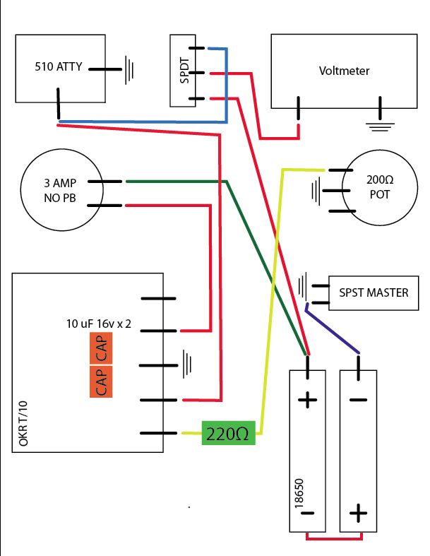
After posting it on breaktru's forum (for approval from the experts), I've learned that fusing it would be a good idea. I'll be running (2) 5 amp ptc fuses in parallel between the battery positive and the fire button. I began tonight by doing all the soldering work on the converter. I should have snapped some before, during and after pics, but I didn't think about it until I was finished. I soldered a 16v 10uF capacitor between the voltage in and the ground, and another between the voltage out and the ground. Vaping can be demanding on a converter like this (repeated short bursts), and the external capacitors will help take the strain off the T/10's own internal capacitors. While not completely mandatory, they will help prolong the life of the mod. Here is a pic of the T10 before (stock photo) 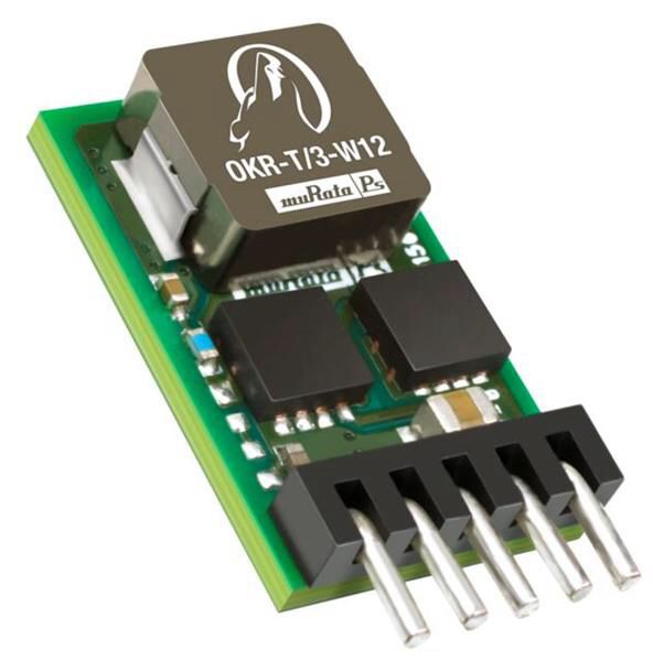
Here it is after I soldered the (2) capacitors, and the 4 wires that connect to the converter. 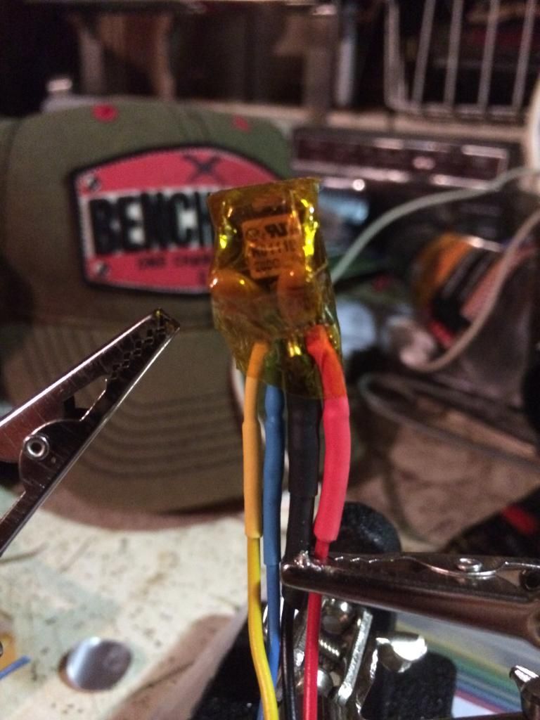
You can see the 2 capacitors under the kapton tape. I wrapped it in kapton to insulate it once it is mounted in the box. Another step that isn't necessary, but this is my first project of this type and I'd rather be safe than sorry. You will also see I covered my soldered connections with shrink tube. I used tube the same color as the wires, because I'm considering using a plexiglass cover on the box if the internals don't come out FUBAR. Here's a shot of the box with the battery sleds sitting in it. I'm just in the early stages of component placement planning. 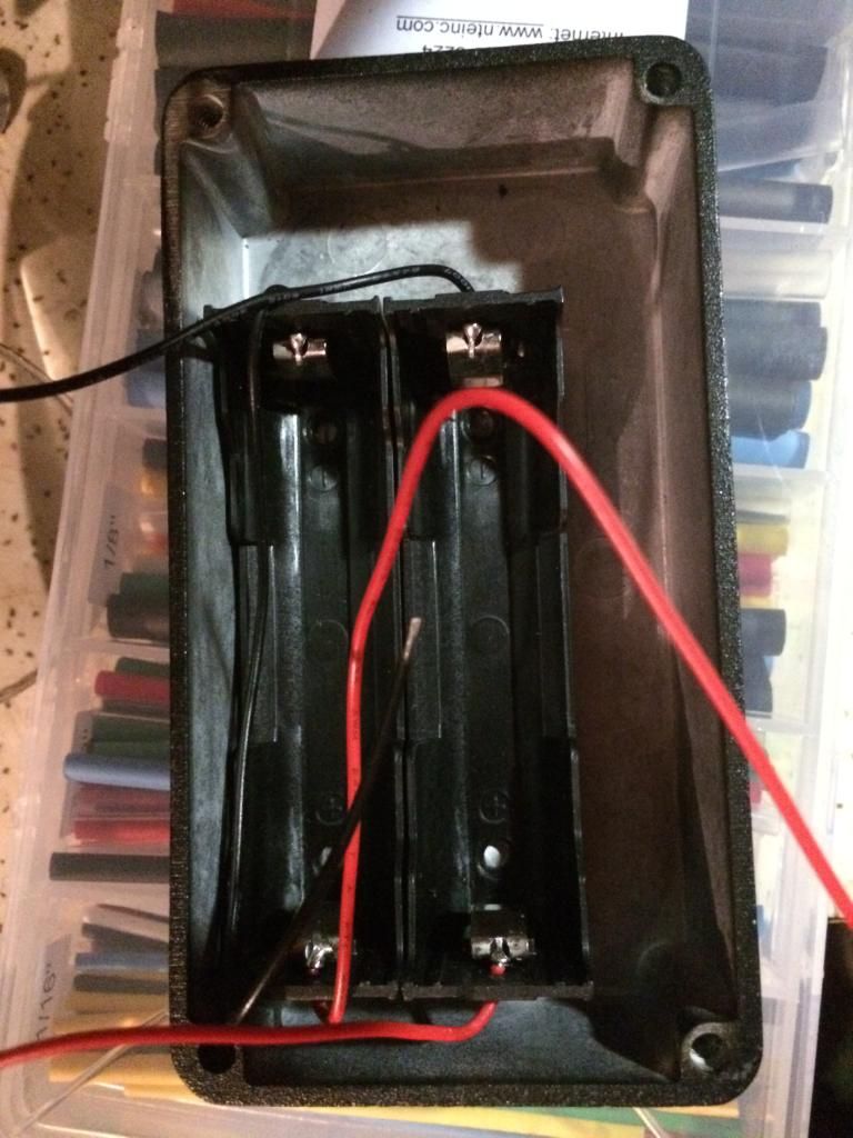
I bought prewired sleds, but the wire seems a little flimsy so I'll be removing them and using my own. I'm using 22 gauge wire for the whole box. I probably should be using 20, but I have no plans to take this thing to 50 watts on a regular basis, and I'll just accept the voltage drop if I do (because I already had a box of colored 22 gauge, and I'm cheap). Well that's about it. I'm still waiting on my fire button, potentiometer and voltmeter. Once I get them and finalize component placement, I'll start working on getting the box cut and drilled. I'll try to remember to document the process a little better. |
|
|
|
[#1]
Not sure what the math is with watts but when I used battery holders like those on my old box mod versions they got a little toasty below .8 ohms.
|
|
|
|
[#2]
Quoted:
Not sure what the math is with watts but when I used battery holders like those on my old box mod versions they got a little toasty below .8 ohms. Well that would be right at the upper echelon. At max voltage (6v), a .8 ohm coil would be supplied 45 watts. .7 ohm would be 51. So I would be somewhere between .7 and .8 at maximum voltage. This thing will spend 98% of its time below 30 watts. |
|
|
|
[#3]
Hells yeah. Looks good so far. Way outside my tech level.
Are you planning on going with magnets to secure the backplate? |
|
|
|
[#4]
Kids went to bed late tonight , so I didn't have much time to tinker. But I received my fire button and voltmeter today and was anxious to test my connections on that tiny converter. So I soldered in the 220 ohm resistor inline with the potentiometer. Pulled out the trusty alligator clip set and wired this puppy up.
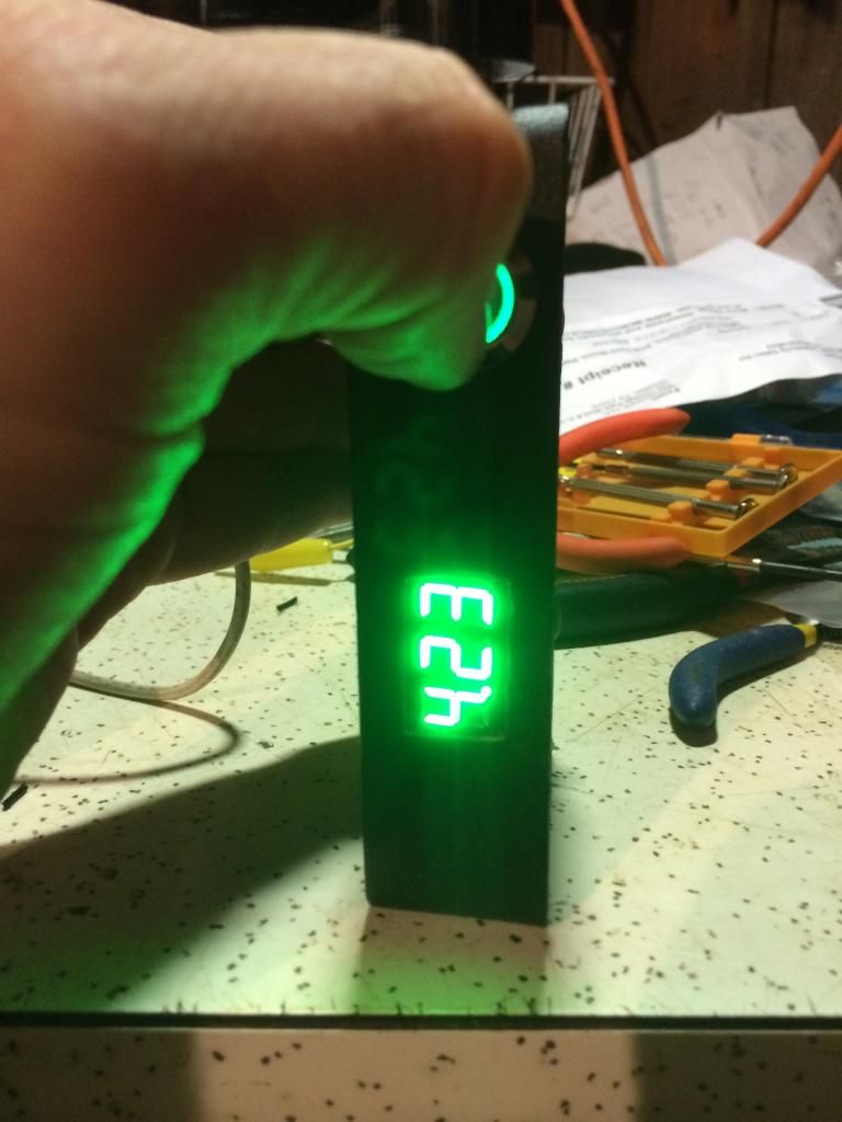
Results are spot on with the desired voltage. Low voltage setting 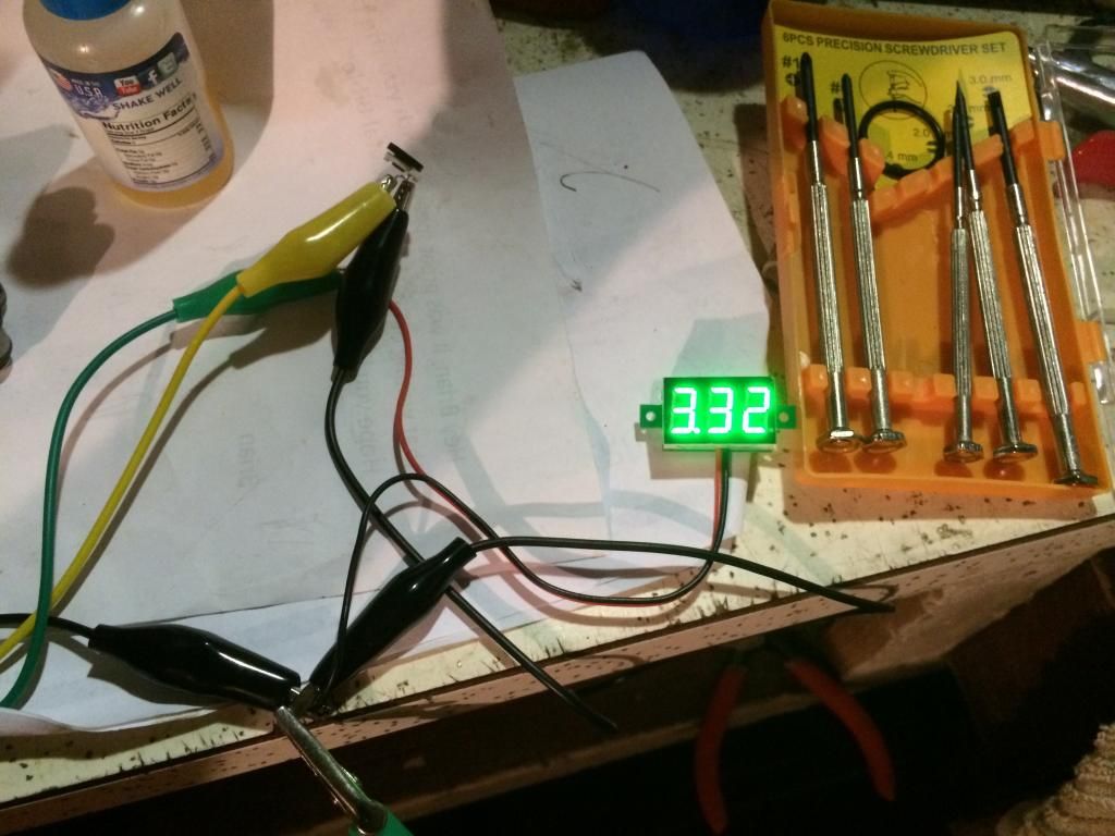
High voltage setting 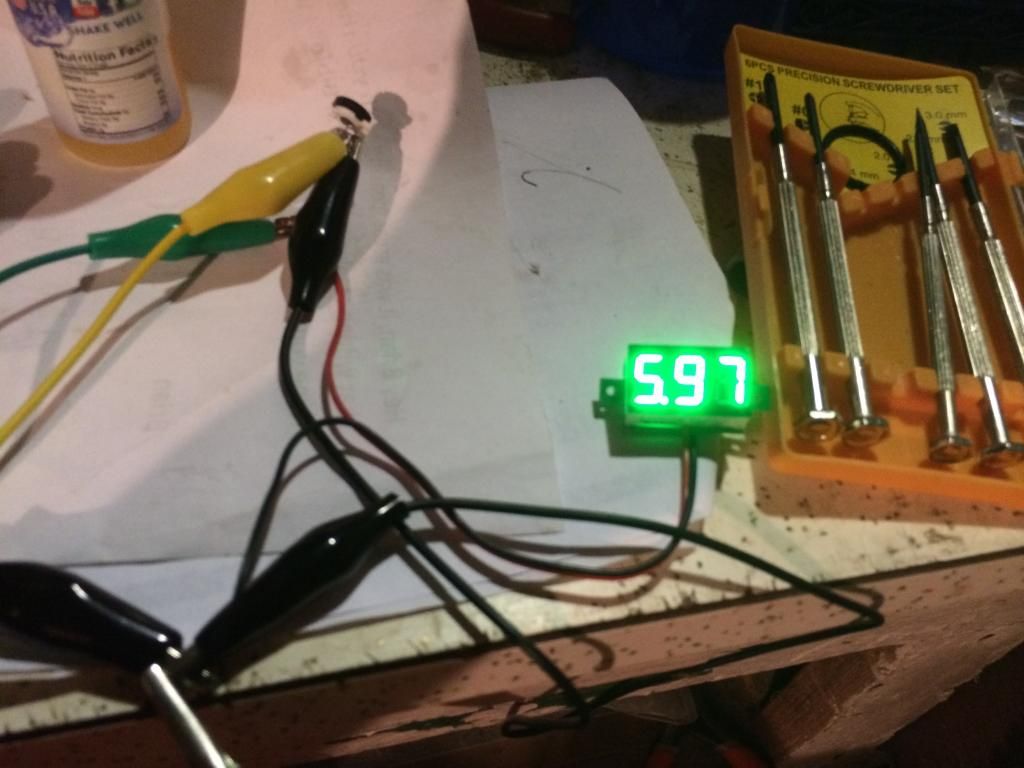
Both are right on the money. I'm really rusty on my soldering skills, so this put a big smile on my face. I probably should have paid more attention to the dimensions on the fire switch I ordered, because it may cause me some problems with fitting it in the box. But it looks tits, so I really want to use it. The green illumination matches the voltmeter perfectly. 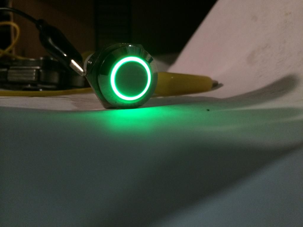
I have had a couple PMs wanting a parts list and cost breakdown. I have a long day at work tomorrow so I'll put it together then. If I remember correctly, I'm at about $60. But we'll see tomorrow how close that is. Also, for those that think this may be out of their skill range, it probably isn't. I took an electronic engineering 101 course at a community college 23 years ago. I was either drunk or hungover for the entire course. I don't remember anything. A couple weeks ago, I ordered a soldering project kit from Amazon for about $11. It even comes with a soldering iron and solder. I have soldered some wires on cars and such over the years, but it had been forever since I had soldered on a printed circuit board. I just wanted to refresh my skills a little with the small stuff like resistors and capacitors. I practiced for a few hours and then felt confident enough to order the parts and jump in. I did a lot of reading on breaktru and the ECF modding forums to determine components. A few weeks ago, I didn't know shit about this stuff. If you're the kind of person that believes he can do anything (with the help of the Internet), you'll handle this. Anyway, back to the mod. I am considering replacing my battery holders. One of the sleds damaged the wrapper on one of my batteries when removing it, and another poster with experience says they're junk. I'm researching new ones now. I also decided to order a different 510 connection from avid vaper. It looks like a beefier setup than the one I had purchased from madvapes. NY, I would like to have magnets on the door, but I'll have to get to that a little further down the road. Maybe on my version 2. No modding tomorrow since I'll be working till 3am. Hopefully Sunday I'll get to the box. |
|
|
|
[#5]
yeah those battery holders will do that. I make my own with contacts from newark for my box mods now. Its easy with wood not sure how you would configure it in a box like that though if you are concerned about a clean look. If not you could just form it out of epoxy putty pretty easily.
|
|
|
|
[#6]
Very cool project. I've kicked around the idea of starting on something like this but then keep reminding myself how long it's been since I've messed with that level of electronics
|
|
|
|
[#7]
Awesome.
For some reason, I'm digging the green. You don't usually see that on mods. It's usually either red, blue or OLED/LED. |
|
|
|
[#8]

Standing by for finished product.... 
|
|
|
|
[#9]
As promised, here is the parts list.
DIGIKEY (1) OKR-T/10 50w DC-DC converter. PN 811-2180-ND. $10.00 (2) 10uF 16v tantalum capacitors - radial. PN 399-9937-1-ND. $1.59/ea ($3.18) (1) 200ohm thumbwheel potentiometer. PN 3352P-201LF-ND. $1.47 (1) Trim resistor - 220ohm 1/4w axial. PN 220ADCT-ND $.46 (2) 18650 prewired battery holders. PN BH-18650-W-ND $2.83/ea ($5.66) ADAFRUIT (1) mini 2 wire voltmeter. $7.95 (1) waterproof metal push button (16mm green led momentary). $4.95 AMAZON (1) Hammond 1590BBK black textured project box. $11.77 (1) 2 position SPST panel mount slide switch 30v DC. ($4.43 for 7). $.64/ea EBAY (1) C+K slide switch pub panel mount SPDT changeover. ($4.78 for 3). $1.60/ea. AVID VAPER (1) 510 modder connection - open center post. $6.99 Total cost for one mod as of now is $54.67. But as you can see, a few of the items I had to buy a higher quantity. You could probably find the slide switches on digikey, but they have so many parts that finding stuff on there gives me a headache. No pricing includes delivery. If figuring total cost you would also have to allow for wire, epoxy and solder. The digikey battery sleds will be replaced when I find a better quality offering. I'll update when I do. I'm also toying with the idea of replacing the thumb wheel potentiometer with a model with a stem, so I can put a green knob on it. I've found the knob I want to use, but need to find the pot with a shaft. Then I need to test it to see if it will go in and out of a pocket without changing the adjustment. If unsuccessful, I'll use the thumbwheel mounted even with the surface, to prevent unwanted changes. As far as understanding the purpose of each component, I'll offer an explanation, but I'm no expert. Battery sleds hold the batteries (duh). They are wired in series, meaning they output twice the voltage as a single battery would. Mah rating stays the same, meaning the batteries won't last longer than a single battery would. 2 VTC5s would still be 2600 mah, but would output the combined voltage, which (assuming they have the same amount of charge) would be twice that of a single battery. Positive power runs from the sleds to the fire switch. In my schematic, the NO in the fire switch stands for normally open (meaning no power gets past the switch unless it's pushed) and the PB means push button. In my setup, the switch has to be rated 3 amps or better, because it is carrying the voltage to the converter. There is another way to wire a fire switch. As you can see on my schematic, there is an unused pin on the OKR-T/10 converter. Using this pin allows you to fire the device with a micro switch that doesn't have to have a 3amp rating, because the voltage to the converter is supplied directly and not through the switch. A lot of people use this setup because they want to use tiny tactile switches. This method requires soldering a resistor between pin 1 and the ground pin. I plan to make one in this configuration eventually. Positive power then continues through the switch (assuming it's pressed) to the voltage in pin on the converter. One of our capacitors are here. The reason it is there is to take strain of the converter's on board capacitors. Capacitors store voltage at a certain level. When the voltage drops from that level, it can be recharged back to that level. This provides steady and balanced voltage. The converter regulates the voltage and sends out the requested voltage based upon the potentiometer setting. The potentiometer can be viewed as a volume knob for mods. In fact, volume controls ARE potentiometers. In this application, the potentiometer is lowering and raising voltage to the coil, just as it lowers and raises sound level on a stereo. The potentiometer has 3 pins. The middle pin is grounded. The pins on the left and right determine CW or CCW rotation on the potentiometer. Test it before soldering it up to make sure it is turning the way you want it to. We have another capacitor on the voltage out pin that serves the exact same purpose as the one on the voltage in pin. So the voltage then goes out the voltage out pin and to the 510 connection and on to the coil. The three lines you see on some components means it is grounded and that particular wire is run to the negative wire (black) on the battery sled. I have a switch installed in the negative circuit, to serve as a master cutoff switch for the entire mod. By breaking the ground to the voltmeter, 510 connection and the converter, we break the electrical circuit and nothing can function. The SPST on this switch stands for single pole, single throw. Works just like a light switch. Flip it one way - mod is on, other way - it's off. There is the other switch, that a has one wire coming straight from the battery sled, one wire from the 510 connection and one wire running to the voltmeter. This switch is a selector switch that has three positions. In the middle position, the voltmeter is off. When the switch is moved to the upper position, voltage from the 510 connection runs through the switch and on to the voltmeter. The voltmeter will then display the vaping voltage. When the switch is in the lower position, voltage directly from the batteries is applied to the voltmeter. The voltmeter will then display the current charge level of the batteries. This switch is labeled as SPDT, which is single pole, double throw. This means it outputs voltage to a single device - the voltmeter (single throw), and can supply that voltage from 2 different sources (double throw). And that about wraps it up. I'm sure things could be explained better by someone that knows more than me. I only have a basic understanding of DC circuits. I'm still waiting on the SPST switch and the 510 connector. I original purchase a prewired 510 from madvapes, but it seems extremely flimsy, so I ordered a replacement from avid vaper. Fat daddy vales sells the one I want (with a spring loaded pin), but they're out of stock until mid June. I bought the open pin version of the connector because I don't like the idea of soldering the wire to the bottom of the pin. I'd rather put the wire inside the pin, and then fill the pin with solder. That way I still get a sealed pin, but I have a stronger mechanical connection between the pin and the wire. Tomorrow I plan on starting on the box and hope to get the display hole finished. More if time allows. |
|
|
|
[#10]
Do not solder that push button. We where using them in some high dollar vet X-ray machines we where building.
The switches began to fail one after another after another. I could not figure out how a simple switch could fail constantly. Finally got in touch with the manufacture and they said they where failing because we where soldering them. 
|
|
|
|
[#11]
Quoted: Do not solder that push button. We where using them in some high dollar vet X-ray machines we where building. The switches began to fail one after another after another. I could not figure out how a simple switch could fail constantly. Finally got in touch with the manufacture and they said they where failing because we where soldering them. |
|
|
|
[#12]
Quoted:
you can solder them but you have to be VERY careful. The heat melts the plastic inside of them. If you get a big fat bead on the wire then apply iron only to the wire and hold it against the switch terminal and pull the iron and blow on it one second after the bead transfers to the post it wont get hot enough to fuck the switch up. Took me about a half dozen failed switches on my mods to figure that out. Quoted:
Quoted:
Do not solder that push button. We where using them in some high dollar vet X-ray machines we where building. The switches began to fail one after another after another. I could not figure out how a simple switch could fail constantly. Finally got in touch with the manufacture and they said they where failing because we where soldering them.
I always used a heat sink when soldering sensitive components, was taught that in class. Alligator clip, or something similar. |
|
|
|
[#13]
Got some time to get back to the mod tonight.
I replaced the battery sleds with 2 new ones from amazon. They have springs, and the batteries move in and out much more smoothly. Still had thin gauge wire on them, so the stock leads were removed and replaced. Rewired sled is on the left. 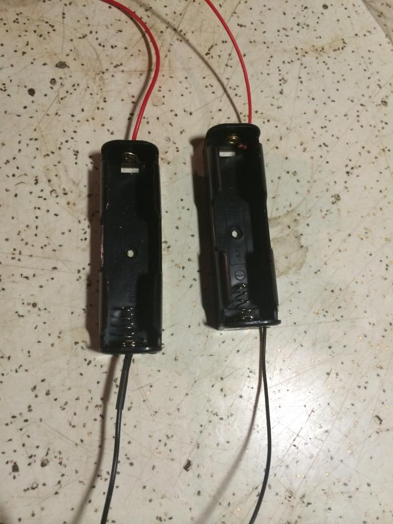
Next up was the 510. The madvapes 510s were very flimsy, so I replaced them with a more robust offering from avid vaper. These are nice, but I still would like to have the fatdaddys spring loaded pin connector. But they are OOS. Here is the connector broken down. 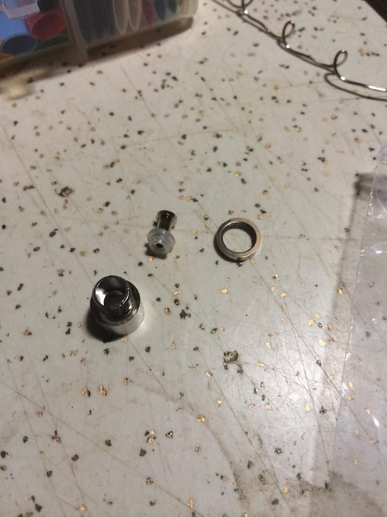
I used a scratch awl to push the pin out. I bought the hollow pin version, and I'm glad I did. Made soldering it a breeze, and now that it's soldered, it's sealed anyway. I pushed the wire inside.... 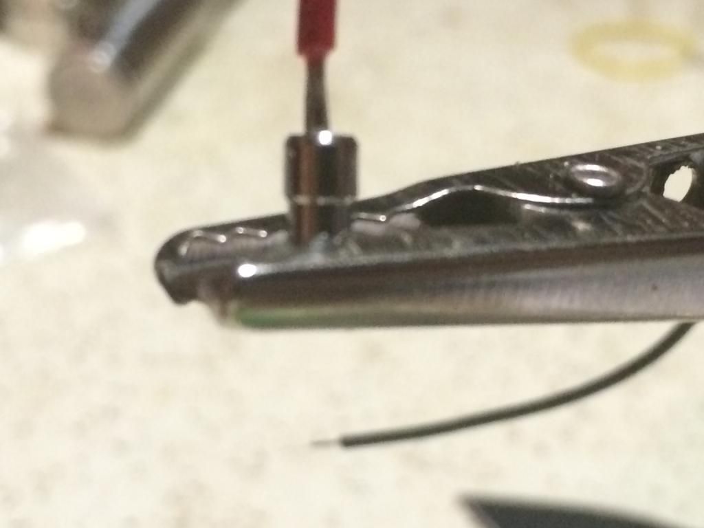
And then soldered it in place. 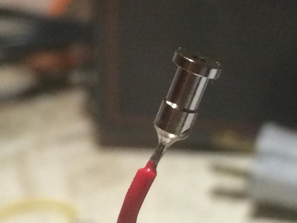
Here is the pin soldered, shrink tubed and the insulator back in place. 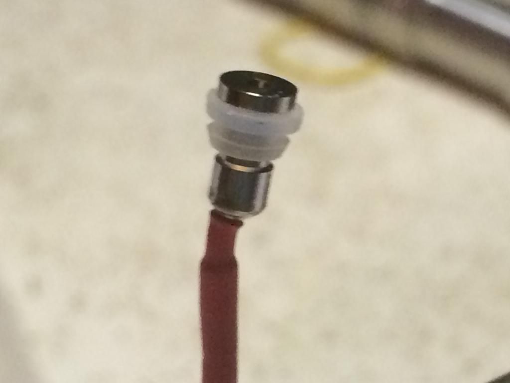
Next up was the ground, which attached to the nut. First I put a nice spud of solder on the nut..... 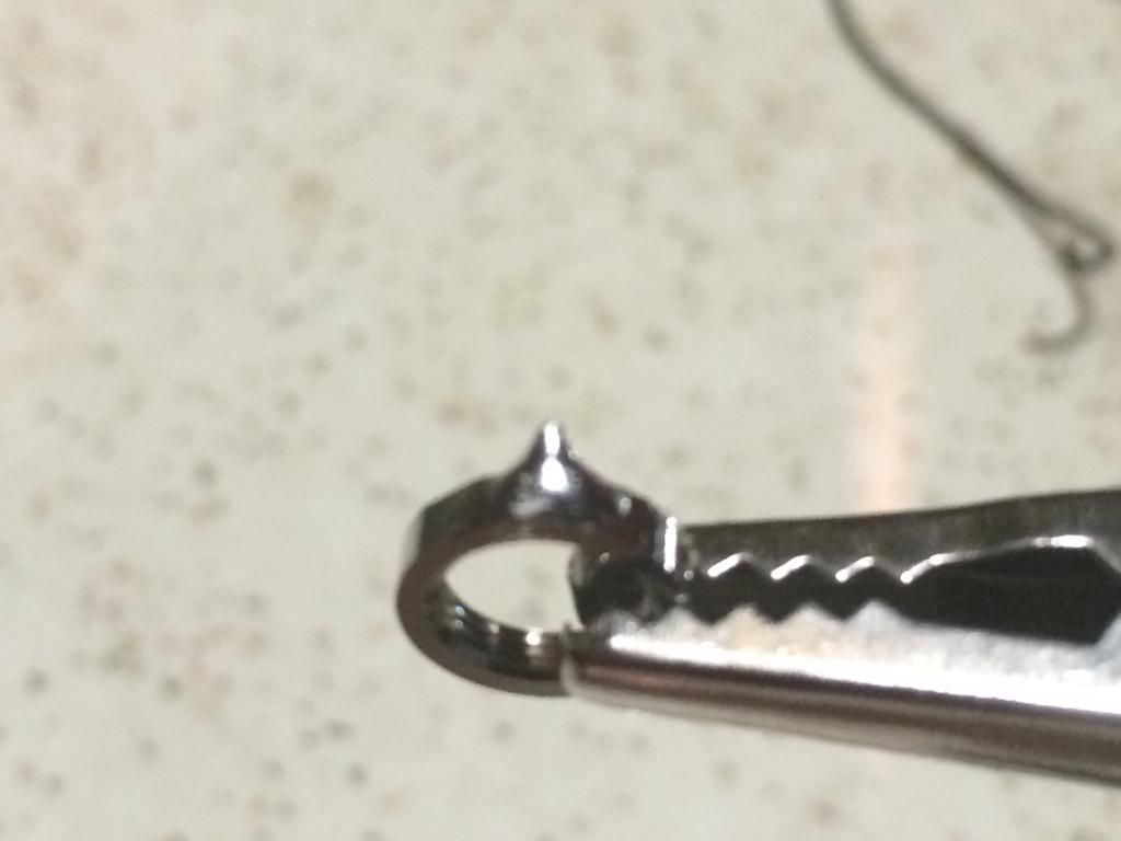
Then just warmed the solder and inserted a tinned wire. 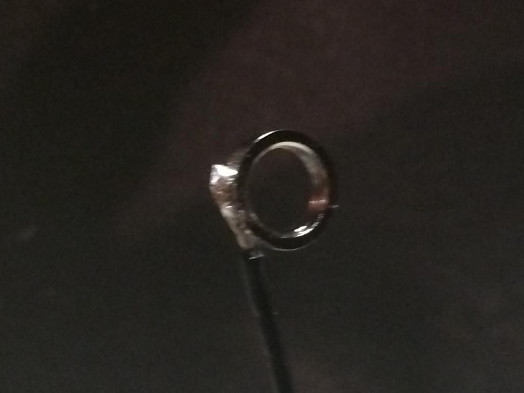
Not the prettiest work, and I've never done this before, so I figured I'd throw my inline meter on the 510 and wire it up to a battery just to be sure. 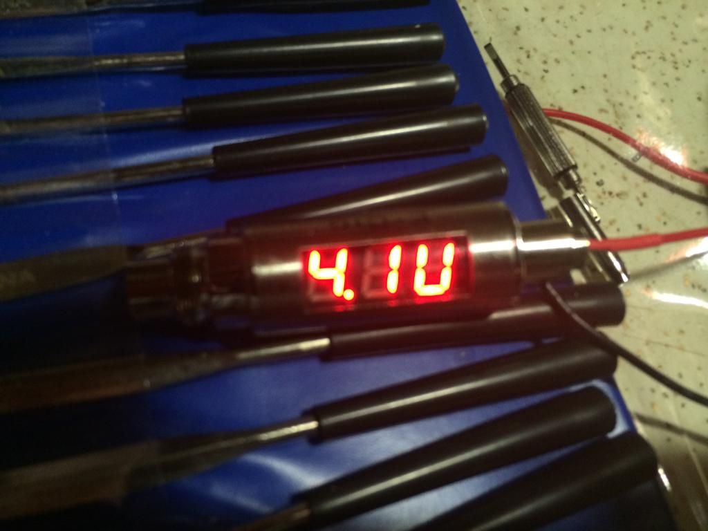
The 510 is good. On to the box. I first measured the pot, button, voltmeter and 510 so I could begin the layout. 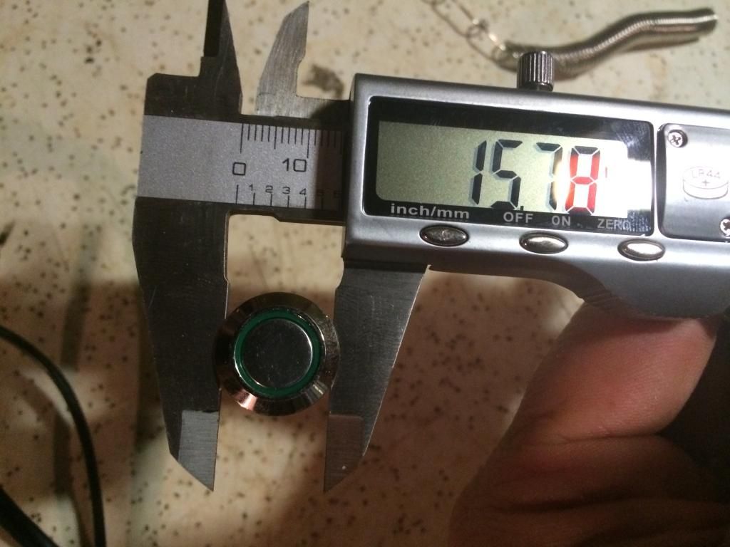
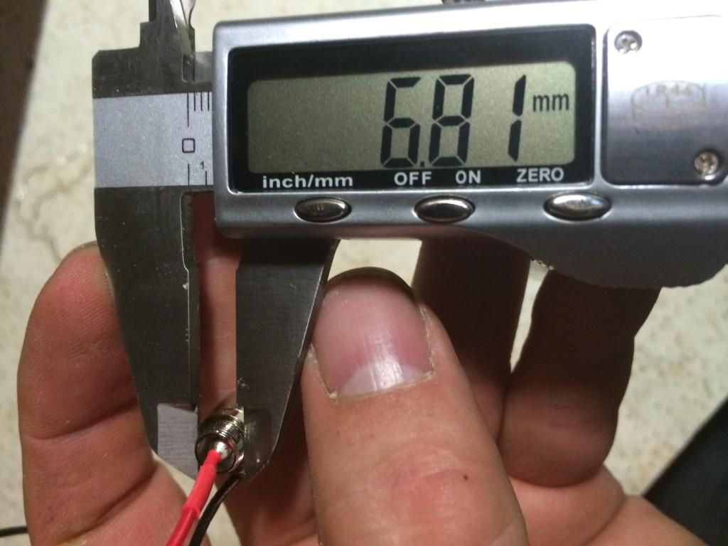
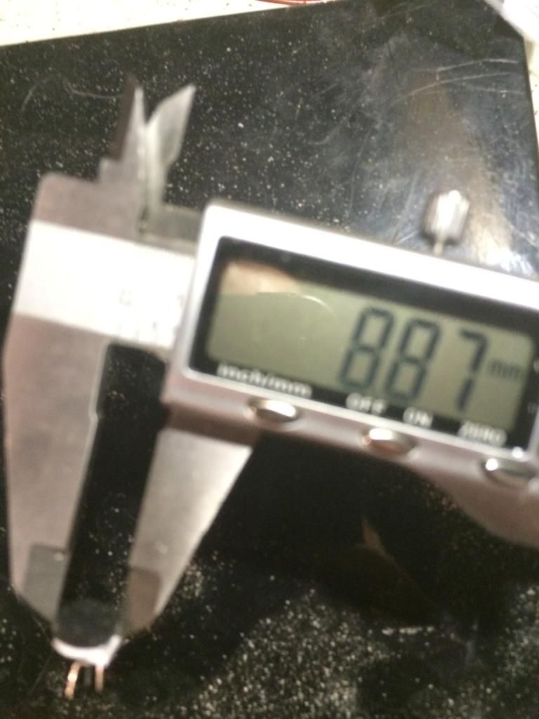
And then took those measurements to the box. 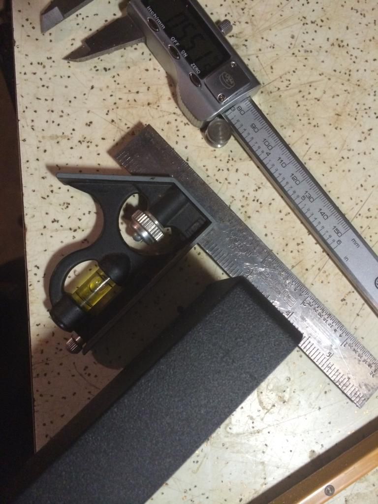
First problem I ran into was, I couldn't find a decent metal drill bit over 1/2". So I started the button hole, but couldn't finish it. 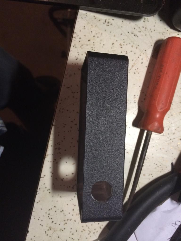
So, on to the potentiometer and the 510. First I laid the holes out and center punched them..... 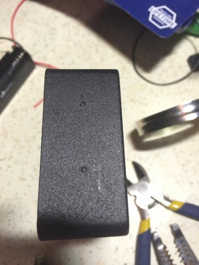
510 in the box..... 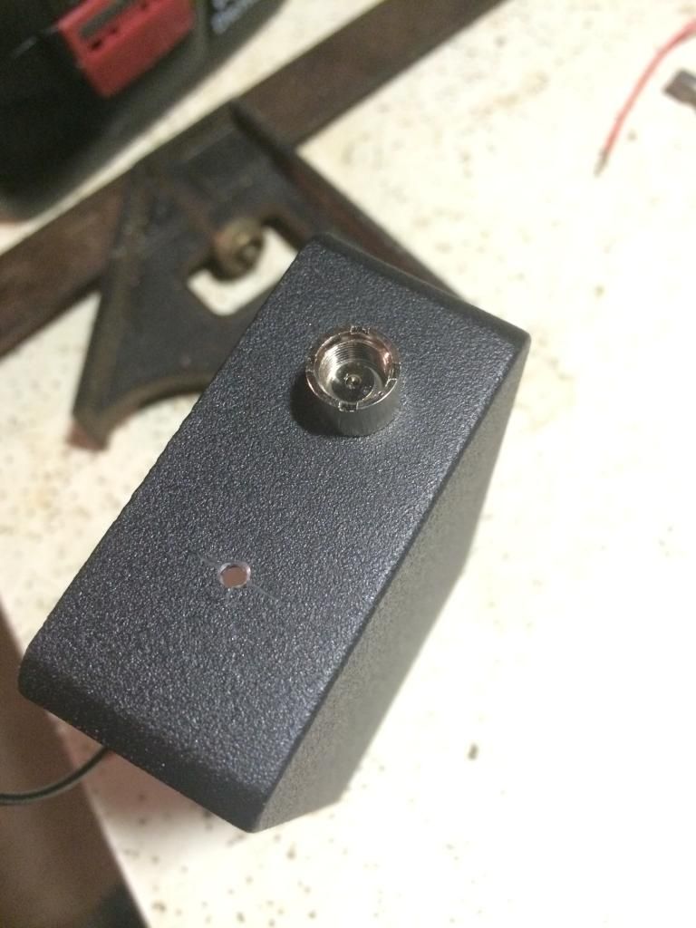
And just for fun, my black fogger on top.... 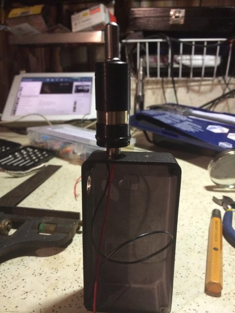
Finished the pot hole and moved on to the voltmeter display. I centered punched a few holes and used the drill and die grinder to get to this point..... 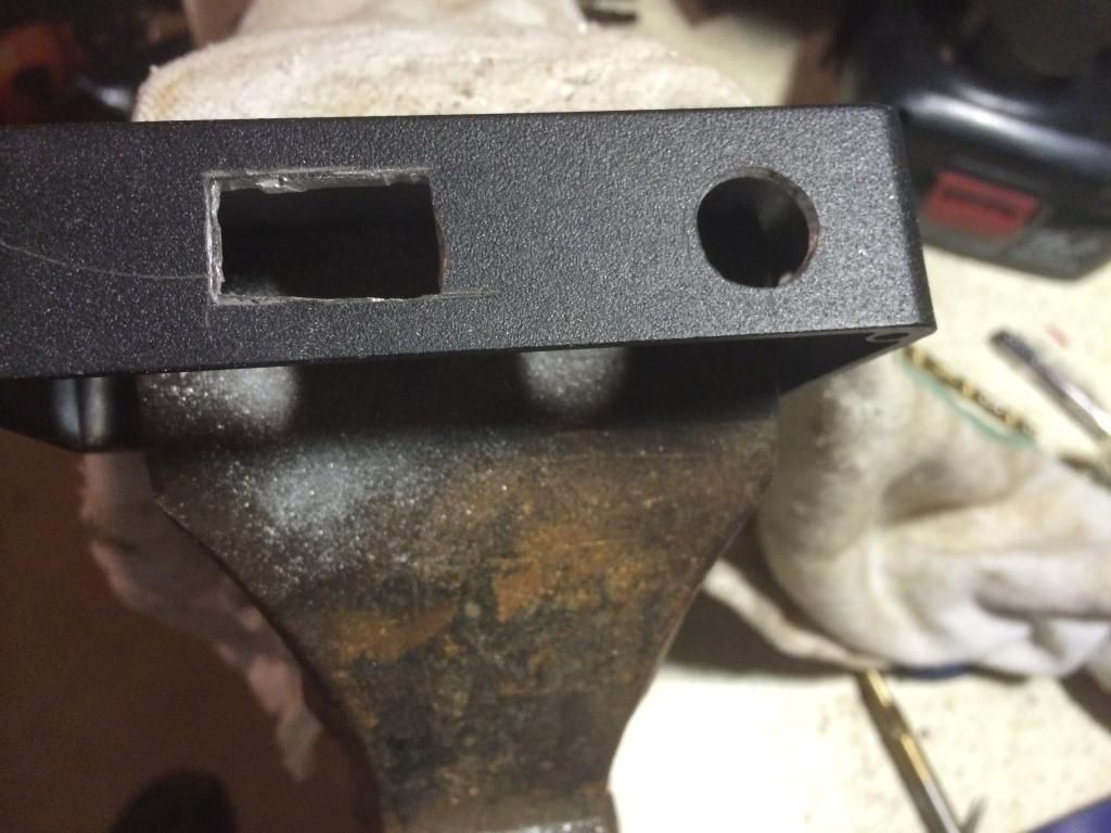
From here I will finish it by hand with needle files to ensure the best fit. As you can see I had a couple slips with the needle file. I'm hoping I can find something to touch it up. Well, that's it for tonight. I'll update when I get another chance to get back on it. |
|
|
|
[#14]
Cant wait to see how she vapes
|
|
|
|
[#15]
Damn, that is awesome work.
How much more of a pain in the ass would it be to flush-mount the 510 connection? |
|
|
|
[#16]
Subscribed
Awesome thread is awesome 
|
|
|
|
[#17]
Quoted: Damn, that is awesome work. How much more of a pain in the ass would it be to flush-mount the 510 connection? |
|
|
|
[#18]
Thanks for the compliments guys. That one scratch with the needle file on the voltmeter hole pissed me off last night and that's when I quit for the night. I do all the work on this after the wife and kids sack out, so I'm not the most wide eyed builder.
Victor is correct on the flush mount. I could build a shelf out of epoxy, but I'm not sure how it would hold up. I have a few pictures floating around in my head about something 22mm epoxied around the 510 on top. I have an idea about a stack of 13mm flat washers (which are 22mm outside diameter), with every other one painted black with a slightly smaller OD. I'm thinking it might give it a heat sink kinda look. But it depends on the weight and appearance. This is the 510 I'll be using for future builds. When they come back in stock, I'm buying a dozen. 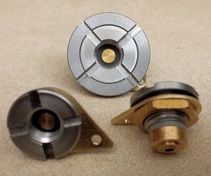
It has a spring loaded pin, a nice solder lug for the ground, air channels pre cut and is 22mm OD. It's also time for a reorder of the switch that runs the voltmeter. The ones I have are a simple on-off switch, and I need an on-off-on. Hopefully I can get them quick. |
|
|
|
[#19]
You could build a little shelf to make the 510 flush from a little square piece of aluminum. Tap a couple tiny holes in your case to screw it to. Polish it up and it would look real nice.
|
|
|
|
[#20]
That epoxy putty is very durable. I built a scope nount out of it for my daughters cricket rifle. It will hold up for mounting that connector no problem.
|
|
|
|
[#21]
Quoted:
You could build a little shelf to make the 510 flush from a little square piece of aluminum. Tap a couple tiny holes in your case to screw it to. Polish it up and it would look real nice. No room on this build. That monster switch enters the box just below the 510, so on this one it has to stay outside. I originally thought about riveting a shelf in there, but I'm building this one basically just to prove to myself that I can. After this one is complete and working, I'll sit back and think about how I can improve it and build myself another version. After I get the exact design I want, I plan to build one out of a brazed copper box. |
|
|
|
[#22]
Came out to the garage to work on the mod tonight, but that hockey game was incredible!
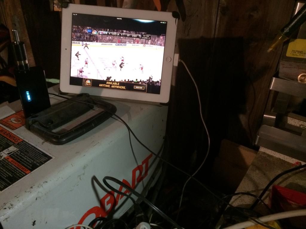
You'll also see in that pic that I got my chana clone (or whatever they're calling it these days to not get sued). Had that fogger on it all day with a 1.0 ohm coil at 25w. This little box has me impressed. I do have the wake from sleep issue about 50% of the time, but I'm not bitchin. I have the black nimbus (from mouse) ready for a sub ohm run on it tomorrow. Back to the mod, I did get a little work done on it tonight. I worked that display hole down slowly but surely. I did go back to the die grinder a couple times, and I wish I hadn't. There is one spot in the hole I'm not happy with. I'm also not happy that I scratched the finish in a couple spots, even with electrical tape surrounding the hole. I am going to have to figure a way to touch the box up, or paint the whole damn box. Anyway, display in.... 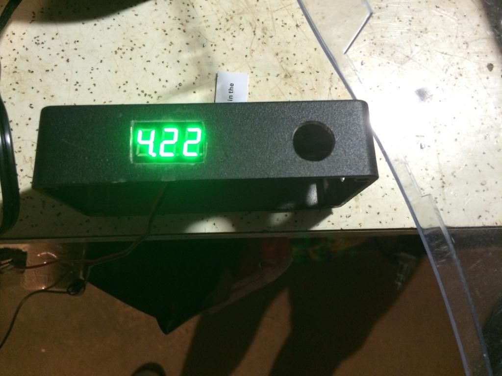
If you look, you'll see several scratches on that box. Products of watching hockey while trying to file. I gave up on finding a 5/8" drill bit in my collection (even though I know I have one). So I reamed with the 1/2" bit and finished it off with a file. That was another mistake. My hole ended up slightly off center. Pick of button installed..... 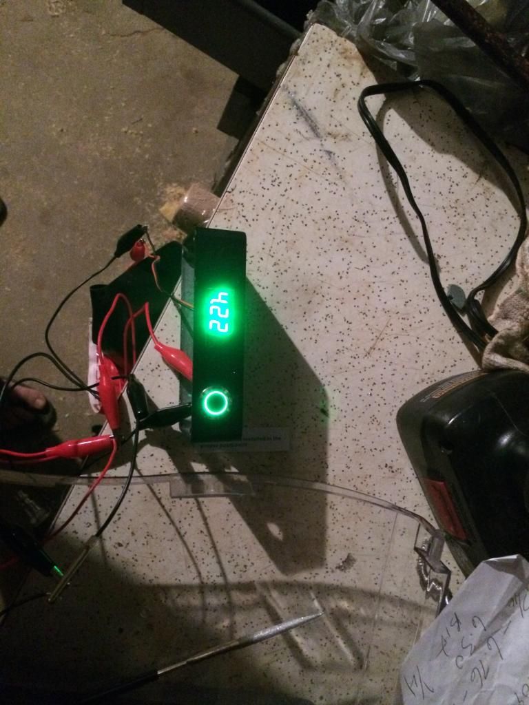
You can tell it is off center. And I just noticed while previewing this post that my toe is in that last picture. I'm screwing everything up tonight. I think it's time for a beer. I may continue to work tonight and screw more things up. I'm considering wiring it up and vaping it sans the switches. I'll update if I do. |
|
|
|
[#23]
Quoted:
Came out to the garage to work on the mod tonight, but that hockey game was incredible! http://i669.photobucket.com/albums/vv59/bwrairden/1563B0C0-0544-4693-8CA3-A5A710FFE837.jpg You'll also see in that pic that I got my chana clone (or whatever they're calling it these days to not get sued). Had that fogger on it all day with a 1.0 ohm coil at 25w. This little box has me impressed. I do have the wake from sleep issue about 50% of the time, but I'm not bitchin. I have the black nimbus (from mouse) ready for a sub ohm run on it tomorrow. Back to the mod, I did get a little work done on it tonight. I worked that display hole down slowly but surely. I did go back to the die grinder a couple times, and I wish I hadn't. There is one spot in the hole I'm not happy with. I'm also not happy that I scratched the finish in a couple spots, even with electrical tape surrounding the hole. I am going to have to figure a way to touch the box up, or paint the whole damn box. Anyway, display in.... http://i669.photobucket.com/albums/vv59/bwrairden/54064F50-DC30-4483-BAB2-02F34A8563E4.jpg If you look, you'll see several scratches on that box. Products of watching hockey while trying to file. I gave up on finding a 5/8" drill bit in my collection (even though I know I have one). So I reamed with the 1/2" bit and finished it off with a file. That was another mistake. My hole ended up slightly off center. Pick of button installed..... http://i669.photobucket.com/albums/vv59/bwrairden/E5AC3B60-B2A6-476C-83A2-63F4B0EB4B69.jpg You can tell it is off center. And I just noticed while previewing this post that my toe is in that last picture. I'm screwing everything up tonight. I think it's time for a beer. I may continue to work tonight and screw more things up. I'm considering wiring it up and vaping it sans the switches. I'll update if I do. You haven't had one yet?? GTFO!!
|
|
|
|
[#24]
I'm really interested in this...It's coming along together nicely
|
|
|
|
[#25]
No beer tonight. I got focused again and went back to work.
First, soldered wire to the potentiometer. Yellow to the trim circuit on the T10 and black for ground. I clipped the unused pin on the pot. 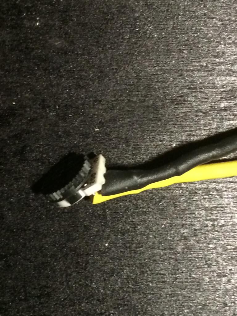
Next up was the fire button. This button has 5 connections. A positive and negative for the led, a voltage in, and then 2 voltage out selections. The button can be wired normally open or normally closed. We want normally open, so the NC connection was capped with a small piece of shrink tube. I ran a red wire to the led positive, the voltage in, and the NO connections. Power comes in the voltage in, and goes out the NO when the button is pressed. I only want the led to light when the button is pressed, so I soldered the NO and positive led wires together, with a pigtail that will continue to the voltage in on the T10. I hope that makes sense to everyone. This is the NO, led positive and pigtail being soldered. 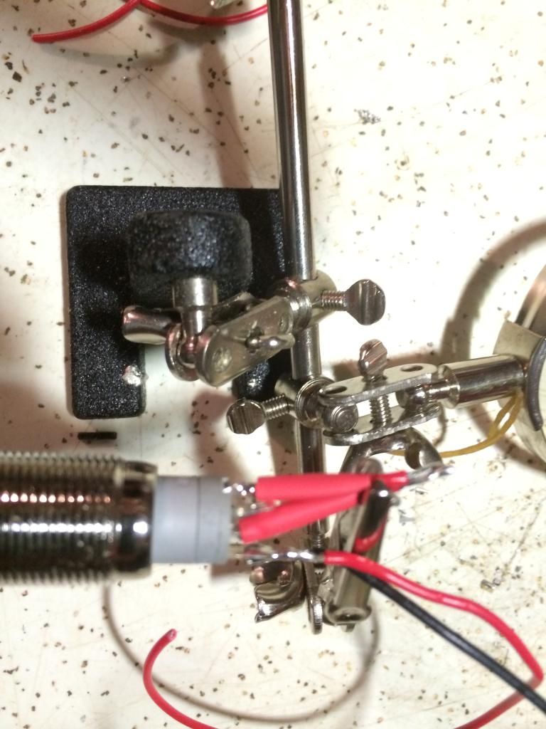
The finished switch has 3 leads. Voltage in, voltage out and the negative for the led. 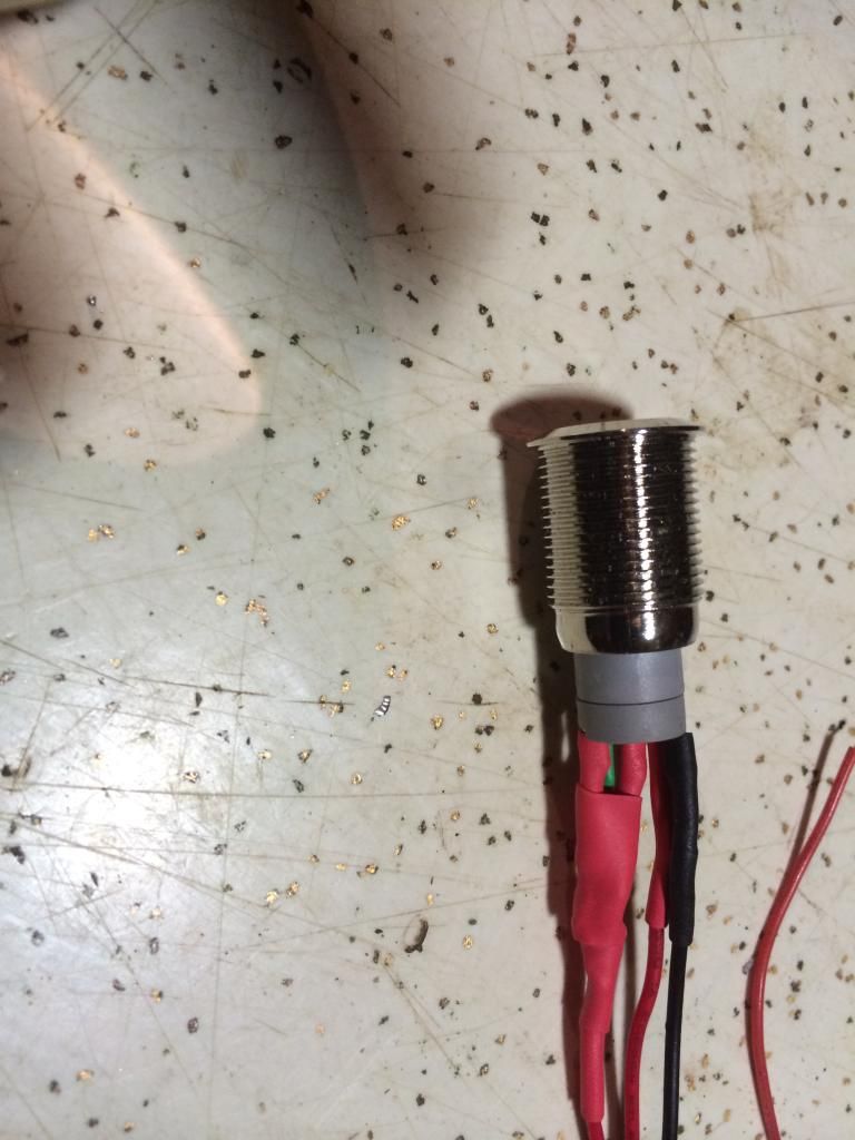
Tested the switch and the pot to make sure everything was functioning correctly. It was. I have backup battery sleds for future tests, so I went ahead and soldered the battery sleds I am using. Wired in series. 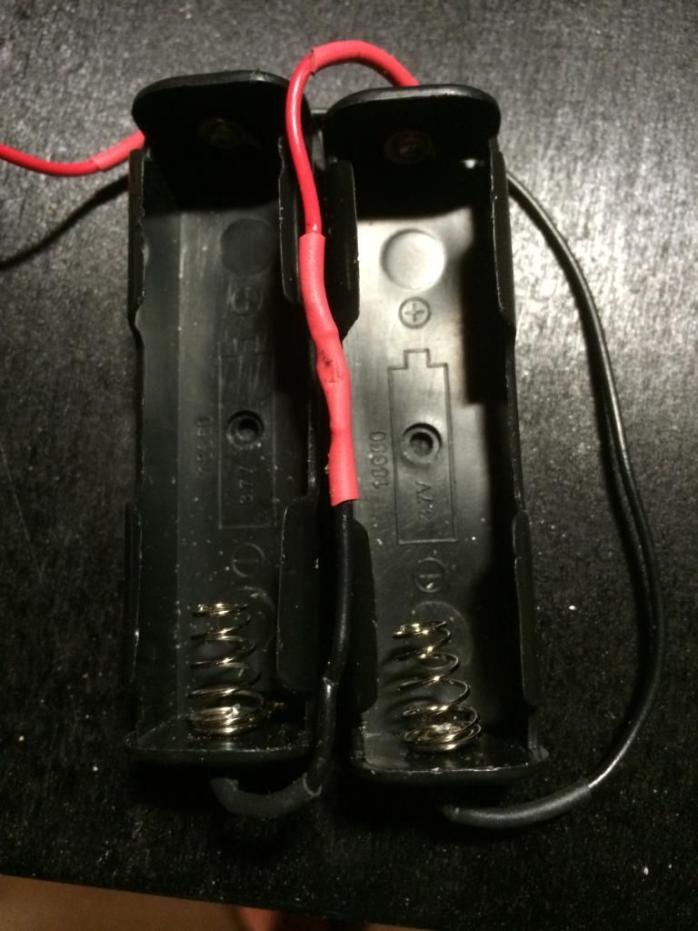
Probably would have looked nicer if I just turned one sled the opposite direction and put a short jumper wire from one positive to the negative on the other sled, but I want both my batteries to go in the same way. This will eliminate any stupid mistakes, which is important because this build does not have reverse polarity protection. Figured it was time to see what it all looked like together. So here we go. Looking straight in.... 
Looks intimidating. And the top view (510 and pot).... 
Not bad. I can live with that. And the off center, scratched up side with a questionable hole for the display..... 
I'm pretty disappointed with my work there. And that's where I quit for the night. I'm still thinking about soldering it up and vaping with it while I wait on the switches. Maybe tomorrow night. |
|
|
|
[#26]
Forgot to mention. Make sure you check the continuity on your rewired battery holder. I used to use those kind and when applying heat for some reason the posi tive end it would break the connection between the two rings on top. Only happened a few times but it was sure a pain in the ass trying to track that down because it would read a closed circuit with the meter but with the battery in it would shift or something and wouldnt work. I started using different top posts with those holders after it happened a few times
|
|
|
|
[#27]
For the janky meter hole maybe cut out a piece of metal larger and lay it over layout t like a frame/bezel ?
|
|
|
|
[#28]
Early start tonight.
First, I made my 2 battery sleds into one with epoxy. Little sanding to rough it up, epoxy in the middle, then in the vise for a few minutes. 
Then on to the pot. The pot wheel has a small stem that goes through the middle, so we obviously can't epoxy that (the wheel wouldn't turn). So I covered the entire thing in kapton tape, and then trimmed off the excess with side cutters. 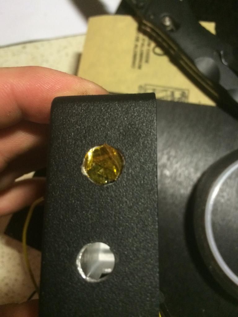
Inside view.... 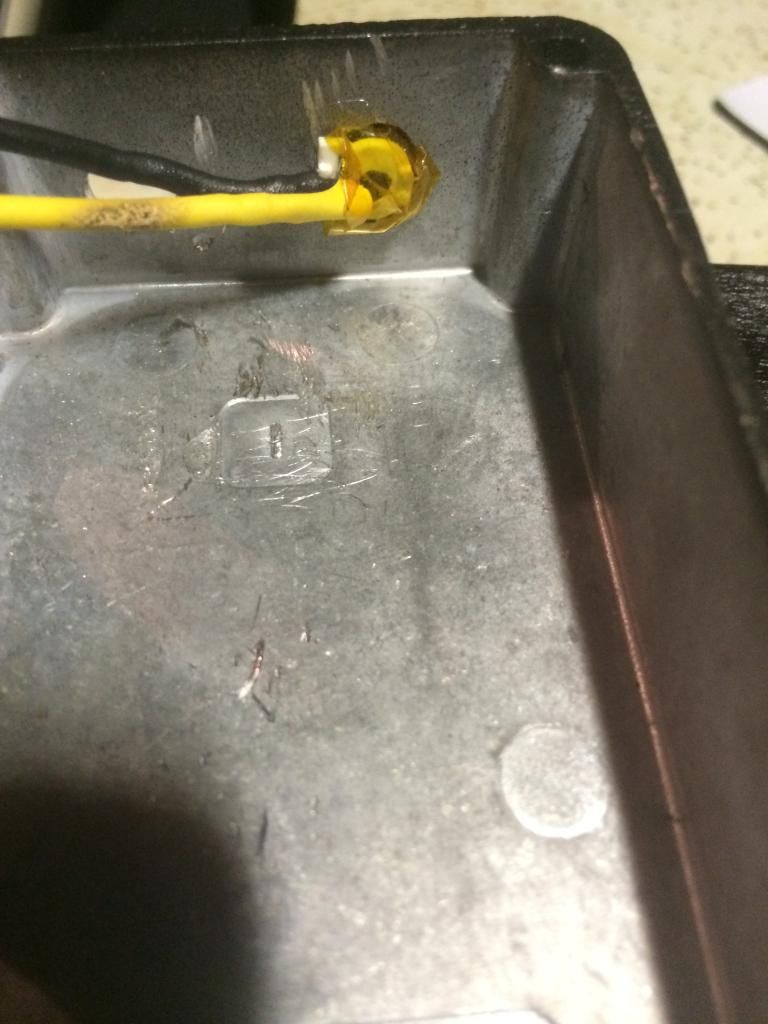
Then the epoxy.... 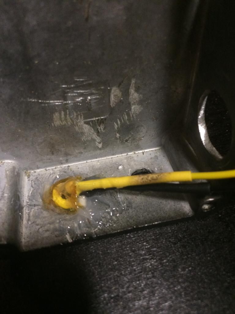
The was a small spot under the wires that I couldn't get to, so I let the epoxy set up for 10 minutes. Once I was sure it wasn't going to move, I pulled the wires up and added epoxy underneath. Pot in place.... 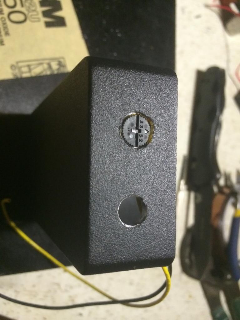
I need to find a razor blade to trim the kapton. As far as the hole for the display, I'm considering paintable caulk around the display as I insert it. Trim off excess from the outside, epoxy in place, and then hit it with some flat black hobby paint. Just an idea. I'm not overwhelmingly concerned with appearance on this one. I don't expect everything to be perfect on my first try. But it can't look shitty either. I decided to vape it. So I took a short video. iPad = can't embed http://youtu.be/q2y3VUIkm3s ETA: shoulda recorded in landscape. My bad. |
|
|
|
[#29]
looks a hundred times better than my first box mod.
|
|
|
|
[#30]
Looking good!!
|
|
|
|
[#31]
Quoted:
Looking good!! |
|
|
|
[#32]
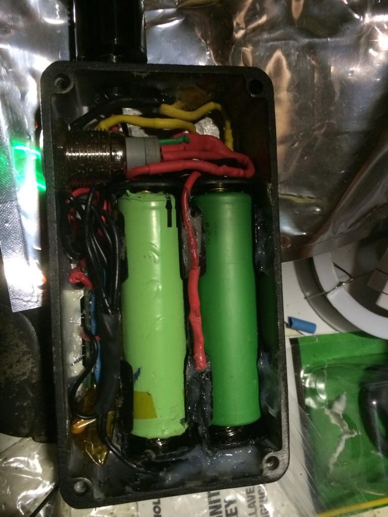
Well, the beast lives. I came out to tinker with it for awhile tonight but I still don't have the switch for the voltmeter. I started soldering a few things up, and stood back and looked at this thing, and decided to make it work. I soldered everything up with no switches. It doesn't have the 510 connector I want, the display hole is a clusterfuck, it has scratches on it, and I now hate the button. So I decided to chalk this one up as a prototype and finish it off tonight. So I did.
2 problems. First, somehow I managed to wire the LED in direct, so it is staying lit all the time. I still am not quite sure how I accomplished that. Second, I can't find the motherf*cking screws for the lid. 
To say that it hits hard is an understatement. I put the nimbus on it, with a dual coil at .6 ohm. I ran it up to 5.24v which works out to 45.76 watts. I threw some 80%vg 12mg moo juice in it and BAM! I had the hiccups for about 10 minutes. 3 hits and I was out of juice, and had to wait a moment before I continued, because the nimbus was so hot that I couldn't take the top off. If you like hot vapor, this is the mod for you. The button sucks. Because it is flush mounted and must be pressed inside its bezel, it's too small. My fingers are too fat to feel comfortable operating it. I'll never use one of these again. A few pictures. I think the interior looks better than these pictures show, but that may just be because I built it. 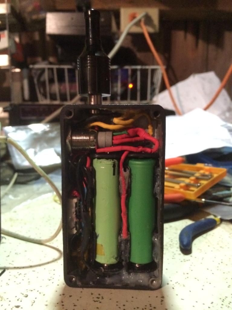
And the stupid button that stays on..... 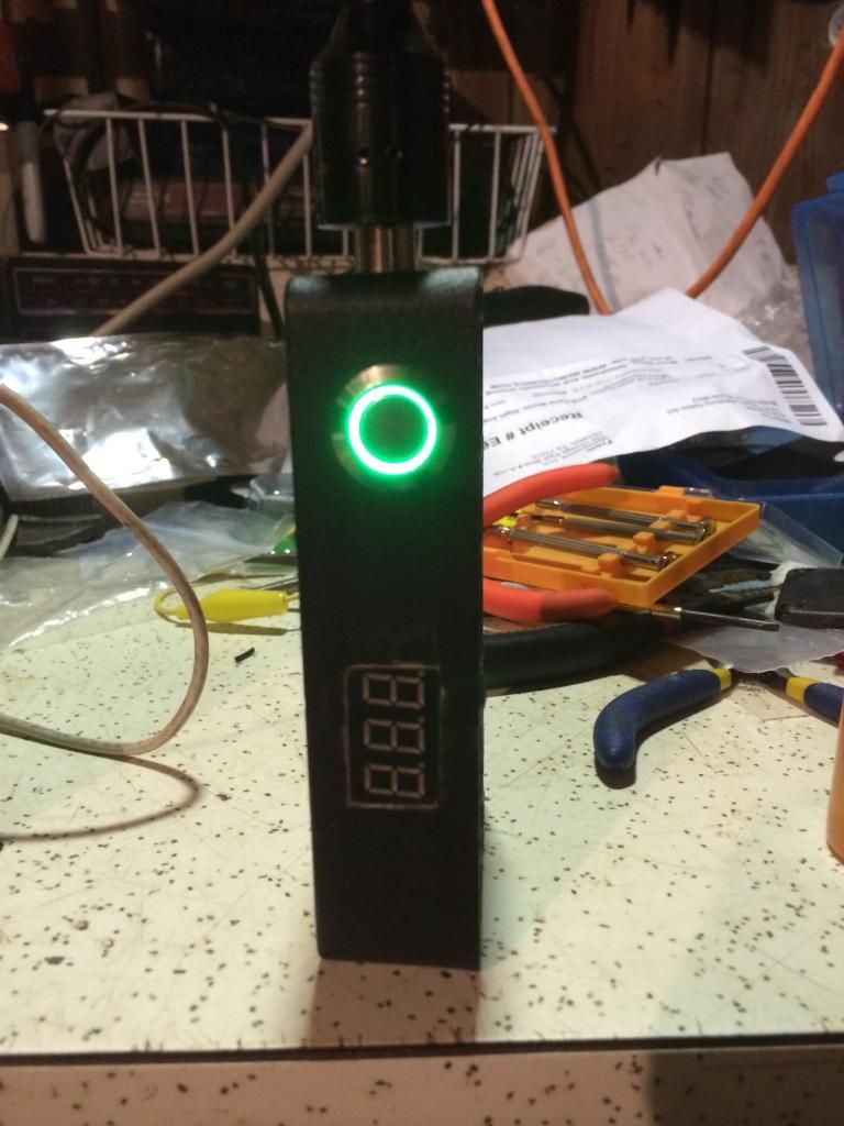
My bench was a wreck because I was looking for the screws. I'm gonna sit here and enjoy it for awhile, and order components for the V2 tomorrow. |
|
|
|
[#33]
Sweet. Your gona vape your brains out, eyes are gona roll back, jk. Nice job. The things ppl develop here amazes me.
|
|
|
|
[#34]
Well, update after day 1 of use. I used it all day long, and couldn't be happier. I was surprised to find that I enjoy sub ohming at high wattage. I spent most of the day with a dripper at 4.75 volts with a .6 coil. That works out to about 38 watts. I went through about 12ml of 80% vg 12mg moo juice with it in about 9 hours.
I fixed the led on the button. Bonehead mistake on my part. I wired it in to the voltage in on the switch instead of voltage out. 9 hours of pretty much constant use left the vtc5s at 3.6 and 3.5 volts. Better than I expected. I've already ordered parts to build 3 more. Because of the size, I'm not ready to sell the Hana clone yet. I also ordered a smaller box, to see if I can fit everything in. I think I am willing to sacrifice the voltmeter to get a smaller footprint. I carry an inline meter with me most of the time anyway. Maybe, maybe not. I bought different potentiometers this time to allow them to stick through the box more. I have to use a screwdriver on this one to change voltage. My EDC knife works, but I'll end up cutting up the plastic wheel eventually. The straight end of the little kayfun keychain screwdriver works, so that's what I used today. Button still sucks. I bought smaller tactile buttons that don't press inside a bezel. I am putting the master switch on the inside on the next one, with magnets instead of screws on the cover. Makes more sense. If I use a voltmeter, I will most likely move it inside as well. Since I didn't have the correct on-off-on selector switch on this one, I wired the voltmeter directly to the 510. It shows me the voltage every time the button is pressed. It's annoying. The new one will have the flat 510 mount instead of it sticking up a 1/4 inch. All the changes will be for better aesthetics. There is absolutely nothing wrong with the way this one vapes. Again, if you think you can't do this, you're probably wrong. If anyone wants to try and needs help, shoot me a PM. |
|
|
|
[#35]
Is that one battery bloated a little?
|
|
|
|
[#36]
Quoted:
Is that one battery bloated a little? Your post made me check, but no, it isn't. Must just be the picture. I don't use it in this mod, it just happened to be laying on the bench next to me when I wanted to test it. I use 2 vtc5s, that I have labeled with 1 and 2. When I take the batteries out to charge them, I replace them in the opposite sled they were in before. That way if one sled is draining the battery more than the other, I'll get equal wear on both batteries. |
|
|
|
[#37]
I am eliminating the volt meter for this build. I've found through using the 50 watt OKR box I built that it really isn't necessary. The nimbus has been on the OKR box 98% of the time since completion. It's built to .6 ohm. Within a day or two I found the wattage I liked best, and I haven't adjusted it since. I leave it at 4.9v, which puts me at just above 40 watts. I can make these adjustments with my inline meter. I also am leaving the pot on the inside for the same reasons. I'm not tinkering with voltage constantly, so taking the lid off to make an adjustment isn't a big deal. Went with a tiny clicky button on this one. Bare aluminum box will be polished (eventually). Here's a look at the size differential. 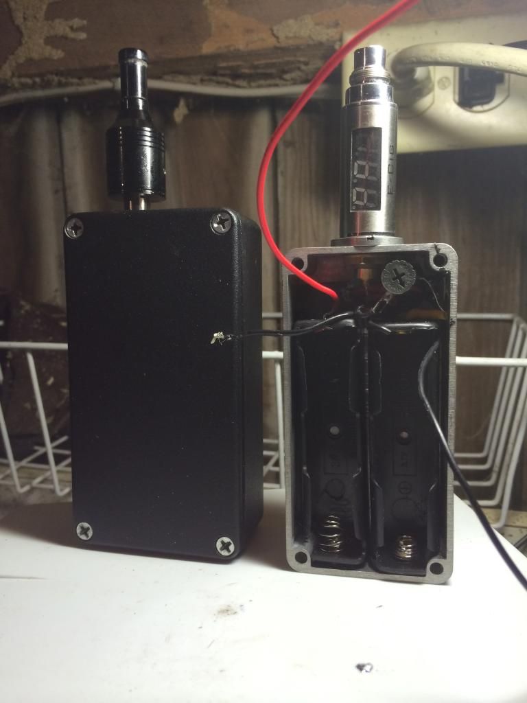
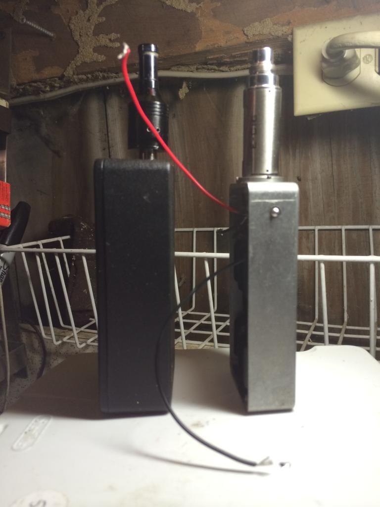
It's a significant difference. Especially with new 510 connection. Couple inside pics: 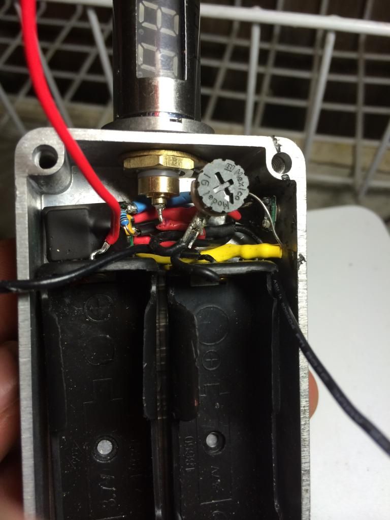
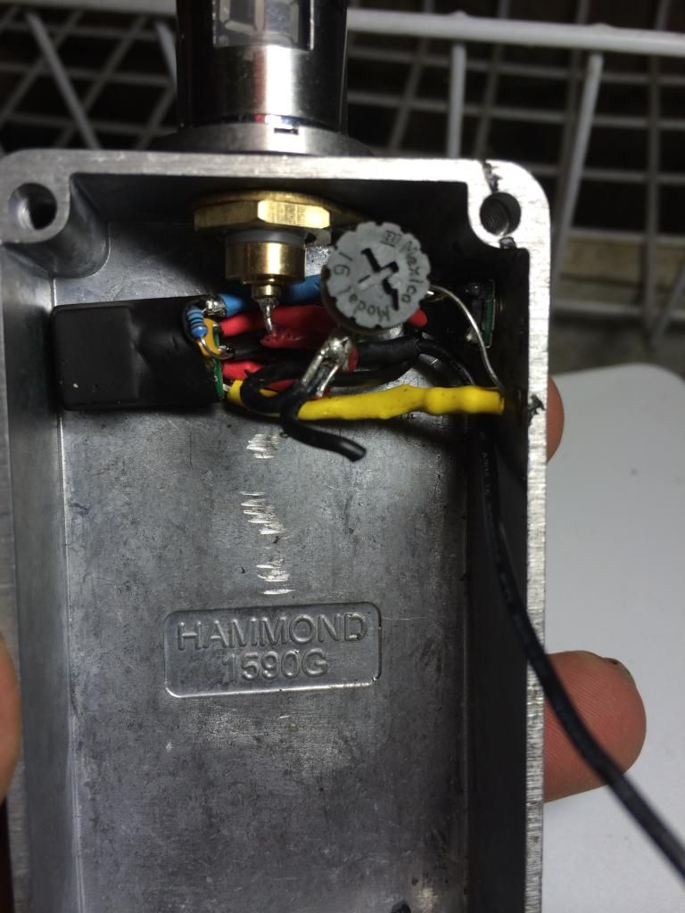
I still have to hit a couple spots with liquid electrical tape. The wires aren't long enough to slide shrink tube on before soldering them. It was a bit of a challenge to get it in there. On the last build, all the wires are longer than necessary and I just folded them into the box. No such luxury here. Everything had to be cut and soldered at pretty near exact size. I had to notch the battery sleds. But they have clearance. Since the nixed the volt meter, I added undercurrent protection to this one with a diode. When my batteries get below 6.2 volts the box dies. I'm waiting on a shipment of fuses so I can wire up the sleds. Should be vaping on it Thursday. |
|
|
|
[#38]
Looking great ...love the updates.
|
|
|
|
[#39]
Very cool. I'm liking the look of the 510 on the newer one. More flush.
|
|
|
|
[#40]
I so want one..how much lol
|
|
|
|
[#41]
I've been using the first one I built now for almost a month without issue, so I think I'm almost comfortable with selling one. To be honest though, I couldn't beat the price of that new sx350 box that is coming out next month.
|
|
|
|
[#42]
Yea,I just put a pre order in on one...hopefully it's gonna be nice like ghee seven 22 I had
|
|
|
|
[#43]
Quoted:
I've been using the first one I built now for almost a month without issue, so I think I'm almost comfortable with selling one. To be honest though, I couldn't beat the price of that new sx350 box that is coming out next month. Do you have the back as a magnetic plastic mount? Interested in how you did the back. |
|
|
 Win a FREE Membership!
Sign up for the ARFCOM weekly newsletter and be entered to win a free ARFCOM membership. One new winner* is announced every week!
You will receive an email every Friday morning featuring the latest chatter from the hottest topics, breaking news surrounding legislation, as well as exclusive deals only available to ARFCOM email subscribers.

AR15.COM is the world's largest firearm community and is a gathering place for firearm enthusiasts of all types.
From hunters and military members, to competition shooters and general firearm enthusiasts, we welcome anyone who values and respects the way of the firearm.

Subscribe to our monthly Newsletter to receive firearm news, product discounts from your favorite Industry Partners, and more.
Copyright © 1996-2024 AR15.COM LLC. All Rights Reserved.
Any use of this content without express written consent is prohibited.
AR15.Com reserves the right to overwrite or replace any affiliate, commercial, or monetizable links, posted by users, with our own.