|
[#1]
Try taking a look here: Ray-Vin - Zero to Complete Lower
|
|
|
|
[#2]
+1 on using Ray's dimensions. Easy peasy.
The front pivot pin hole will be your main datum point. Just make sure you mic the width of your raw forging at several places and jot down the readings as they will vary a bit. http://arlower.ray-vin.com/ar15 |
|
|
|
[#3]
Thanks.
I've downloaded and printed all those files out. One thing I have done that I think makes it easier to machine the lower is that as soon as the takedown pin holes are drilled, which is my first operation, I bolt the lower to the fixture plate below it. I do this by pre-drilling the fixture plate in the same spots using a #7 drill and tapping them 1/4-20. Screw the lower to the plate using the takedown pin holes and two suitable allen head cap screws, and life is good. Plenty of holding strength and NO clamps on the workpiece. For the deck cut, just spend the money and buy yourself a good 1.5" diameter end mill and the entire deck cut operation becomes two moves in one path. Straight across and then out and away. Done. No fumbling with trying to interpolate steps to get the curve right. I use a modified 1.5" diameter keyway cutter for this job. Its modification consisted of sending it to the local tool grinder and having the flat face of it turned into a facing cutter. This allows me to plunge cut the corner of the deck in a single operation, leaving a very smooth finish and it easily handles this in ONE pass. Since I recently tuned up my mill, it's been an absolute pleasure to use. It has ball screws on the X and Y axes so there's no slop or backlash. And having a nice four axis (three currently installed) DRO system just makes it as sweet as it can be without having full CNC capability. It really doesn't hurt at all that it uses QC30 quick change toolholders (which I retrofitted into this formerly R8 spindle equipped mill) and I have plenty of toolholders. I also do not skimp on cutters. I don't think I have a single HSS cutter that I actually use, unless it's an inch in diameter or larger. I only buy and use top brand carbide cutters. Ultratool, Mastercut, G.W. Schulz, etc. No Enco or Chinatrash cutters in my tool cart, please. The assured accuracy of diameter, long tool life, and surface finish quality is well worth the extra money to me. I even use a 3" carbide insert face mill with octagonal or round inserts, and also have a 2" version. I wish I had a 4" version. You'd think that with a setup like this I'd be making parts and money every evening and weekend, but I'm just a hobbyist and sometimes months pass without me so much as turning the light on in the mill's room, except checking to make sure it's oiled and nothing's trying to rust. My setup is really an extreme case of overkill for what I really NEED, but I've always been good with overkill, when it fits within my budget. It just so happens that the bad economy has made a buyer's market for manual machine tools. You can score a full size Bridgeport or clone mill with lots of life left for as little as 500 bucks. Maybe even less. I scavenged my DRO system by getting in touch with the local Acu-Rite dealer and getting some units that they took on trade-in. I then got lucky and scored several deals on brand new in the box Heidenhain scales, for stupidly low prices, and then found a major dealer of both brands, and traded Heidenhain scales for the Acu-Rite scales I needed, on a one for one basis. I'd have used the Heidenhain scales except I was never able to find a Heidenhain DRO that fits my needs at a price I can pay. Those are expensive. But my Acu-Rite DRO 300M is a very capable unit that will display part diagrams and give step by step instructions to the operator, if I take the time to program it that way. Which I've only done as a learning experience, and would be worth the time if I had to do a fairly large run of identical parts. CJ |
|
|
|
[#4]
Pictures didn't load.
|
|
|
|
[#5]
Quoted:
Pictures didn't load. No kidding. I use a clapped out Bridgeport (yes, they do wear out) with Chinese tooling and Ebay cutters. The Chinese stuff varies from really good to terrible, even from the same tooling set. |
|
|
|
[#6]
CNC Guns has solidworks and IGS files for an AR lower.
If you havent seen them already: http://www.cncguns.com/downloads.html |
|
|
|
[#7]
I'll be back in the shop tomorrow evening to do more work. I'll get pics then.
There's also a typo on the usual blueprint. The mag release button's slot width is called out as .312. It's really .318. Just try to find an end mill with a diameter of .312 unless you get one reground! CJ |
|
|
|
[#8]
Bump for pics.
|
|
|
|
[#9]
I just started reading through this and wanted to comment on a couple things.
The blue print is dimensioned and toleranced for the application. I can think of only rare occurrences that you would have a single common datum. You will end up with improperly toleranced features. For example, you would dimension from a datum to a bolt hole pattern and then dimension and tolerance the bolt hole pattern for the mating component and not from an unrelated datum. Also, you do not want to machine a critical slot using the exact size cutting tool. So for your .312 slot you would not use a .312 or .318 end mill. You would use a smaller diameter endmill and machine it to size. I can tell you that I design in and have machined .312 slots frequently using standard end mills. Don't assume it is a typo. I'm looking forward to seeing some pictures of your progress and how it turns out. |
|
|
|
[#10]
I expect to get back to it this weekend.
I've had a little consultation with a friend of mine who owns a machine shop, and I'm going to get the mag well cut via water jet. We're looking at what it would cost to take raw forgings and do a minimal amount of work to them, specifically the deck cut and the mag well, and if the cost is low enough, and those two cuts don't meet the ATF's definition of 80 percent done, I may buy a pile of the forgings, get this work done, and sell them to builders for a very reasonable price with the hardest part done for them. I figure that the deck cut, the takedown pin holes, and the mag well operations don't yet equal 80 percent. I might even go so far as to send an example to the ATF for a ruling on this. With paperwork in hand I would have no worries about selling them. I'm a big fan of dimensioning off a single reference point whenever it's possible and practical. If I can avoid having to shift my DRO's reference points in mid-setup, I'm happy about that. I've now fine tuned my mill to the point that its dimensional error is down to .0001 per inch. And I can get it even closer by adjusting the scale compensation factor. The error is now at 100 PPM so I shave off 100 PPM in the scale compensation and at that point the error should be unmeasurable unless you can measure to five digits past the decimal point. At this point, cutter variations are now greater than scale inaccuracies. CJ |
|
|
|
[#11]
I wouldn't use waterjet unless he has a machine with a fourth axis head, the waterjet will leave a beveled cut over the entire depth of the magwell. Cut a test piece first and you will see it clearly. Also, the tolerance capability of the machine may exceed what is required of the magwell.
I recommend wire EDM. Sounds like you are having fun with it. |
|
|
|
[#12]
The pre-cut estimates are that the waterjet will result in a mag well that will be, at most, .008" wider at the insertion end than at
the top surface. I think that would be quite acceptable. It can also be cut with a slight angle on the cuts to compensate for the slight spreading of the jet. It'll be tested on scrap before committing to cutting a lower forging. The reference standard will be that a pmag has to drop free. No tight mag wells. I'll be happy if a little finish filing is required. CJ |
|
|
|
[#13]
The water jet thing sounds cool. I have set up and ran a CNC water jet. In your first post you stated you had your mill down to .0005" in 8.0" Then in your last post you state you now have it down to .0001" per inch. Well .0005" in 8" is better than .0001" per inch !! How much does the indicator move when you lock the knee or one of the other axis.
I am a machinist with 25 years of experience with both manual and CNC machines. I doubt your Bridgeport type mill is as accurate as you may believe. What kind of read out does it have? Have you ever bored holes with it and confirmed their locations with precision measuring equipment? I'm not in any way saying you won't make good or even excellent parts. I'm just saying if you can machine the take down pin bores CTC distance within +/- .002" in both directions you will be doing well. BTW: What is the tolerance on the 6.375" spec? |
|
|
|
[#14]
I've made some test cuts and had them measured via a Faro arm. I then use the scale compensation feature in my Acu-Rite DRO 300M,
and make additional test cuts and have them measured. I do the measurement from same side cut surfaces. Left side of cut to left side of another cut, spaced exactly X inches away. This way I don't have to worry about diametric cutter tolerances throwing the results off. When I first got this setup, the scale compensation was set to a ridiculous number and the work was way off, several thou per inch. I guess that's understandable as I got the DRO from one source, and the scales from another. I'm now zeroing in on as close to zero error as can be reliably measured. I made a compensation adjustment and then found out I'd gone in the wrong direction. The manual for the DRO really wasn't clear if adding points to the compensation adjustment would shorten or increase the actual length of travel. I was wrong the first time. I'm not saying I can hold tolerances of .0001 or better. I'm saying I want to iron out the scale compensation factor so that there's as little error as I can get. If I make an error, I want to be able to only blame myself, not the scales or the machine. The nice thing about an error of .0001 per inch is that it's really easy to calculate the error in PPM. It's 100 PPM. The compensation factor is entered in PPM. i don't even bother to read the dials anymore. It wouldn't do me any good anyway, as they're graduated for inch measurements and the ball screws in the mill (Yes, it has ball screws instead of lead screws on the X and Y axes) are metric. Relying on the dials would guarantee that you'd always be totally off by insane amounts. I got the mill with those ball screws already installed. Given that they really make the dials useless, I'm not so sure that I wouldn't rather just install fresh lead screws instead if I had to do it all over again. But now, I'm so used to using the DRO that doesn't matter. CJ |
|
|
|
[#15]
Quoted: I use a modified 1.5" diameter keyway cutter for this job. Its modification consisted of sending it to the local tool grinder and having the flat face of it turned into a facing cutter. This allows me to plunge cut the corner of the deck in a single operation, leaving a very smooth finish and it easily handles this in ONE pass. CJ I just want to see pictures of this 1.5" "end cutting" woodruff key cutter. |
|
|
|
[#16]
 I had the local tool grinder/custom tool maker put an end mill type face on it. He does all end mill resharpening, and makes customized cutters, for machine shops all around the area. I've had him make two other custom cutters for me as well, which I use for certain parts of guitar construction. He did a nice job modifying the keyway cutter, and it works well. Of course, it can't take a big cut but I'm not asking it to do that. CJ |
|
|
|
[#17]
Originally Posted By cd johnson:
I've made some test cuts and had them measured via a Faro arm. I then use the scale compensation feature in my Acu-Rite DRO 300M, and make additional test cuts and have them measured. I do the measurement from same side cut surfaces. Left side of cut to left side of another cut, spaced exactly X inches away. This way I don't have to worry about diametric cutter tolerances throwing the results off. When I first got this setup, the scale compensation was set to a ridiculous number and the work was way off, several thou per inch. I guess that's understandable as I got the DRO from one source, and the scales from another. I'm now zeroing in on as close to zero error as can be reliably measured. I made a compensation adjustment and then found out I'd gone in the wrong direction. The manual for the DRO really wasn't clear if adding points to the compensation adjustment would shorten or increase the actual length of travel. I was wrong the first time. I'm not saying I can hold tolerances of .0001 or better. I'm saying I want to iron out the scale compensation factor so that there's as little error as I can get. If I make an error, I want to be able to only blame myself, not the scales or the machine. The nice thing about an error of .0001 per inch is that it's really easy to calculate the error in PPM. It's 100 PPM. The compensation factor is entered in PPM. i don't even bother to read the dials anymore. It wouldn't do me any good anyway, as they're graduated for inch measurements and the ball screws in the mill (Yes, it has ball screws instead of lead screws on the X and Y axes) are metric. Relying on the dials would guarantee that you'd always be totally off by insane amounts. I got the mill with those ball screws already installed. Given that they really make the dials useless, I'm not so sure that I wouldn't rather just install fresh lead screws instead if I had to do it all over again. But now, I'm so used to using the DRO that doesn't matter. CJ I'm not crazy about Faro arm measurements but in my case it was measuring things that were 6 feet or more apart. Even the CMM has it's flaws but usually a good operator can work them out. With 25 years behind me you can bet I never want to have to use the dials on a mill ever again. Mostly because I have been spoiled with digital read outs. I can't even imagine trying to make something with a lead screw machine and dials. I have a friend who also has a tool grinding shop. That is one area I haven't worked in yet. He invited me to come out and see if I like it or not. So hopefully by next year I will have some tool grinding experience too. May be a good part time job after I retire. Good luck with your project and thanks for not going ballistic on me. |
|
|
|
[#18]
I'm not the type to go ballistic on people who know more than I do about the topic in question, and are just asking honest questions.
I'm an amateur machinist, at best, but I understand the basics well enough. And one thing about a manual Bridgeport style mill is that it's actually kind of hard to make the cutter do the wrong thing. Most modern cutters are designed for speeds and feeds that I can't even approach by hand. Sure, I could break a small diameter end mill, but with a 1/2" carbide end mill, it'll take more than my 2 HP machine has to give. At least in aluminum. CJ |
|
|
|
[#19]
Quoted: He did a nice job modifying the keyway cutter, and it works well. Of course, it can't take a big cut but I'm not asking it to do that. CJ And now for the real question...... How much??? |
|
|
|
[#20]
It was a while ago but I think he charged me 10 bucks. Seems fair to me.
It sure was a lot cheaper than buying a 1.5" diameter end mill of any kind. |
|
|
|
[#21]
If you are still in need of .312 diameter end mill you can get them from MSC. They have dozens of options from $20-$35.
|
|
|
|
[#22]
Not too long ago I bought a USA made 3/4" carbide end mill. It has been used to remove no more than 20 cubic inches of 6061,
taking moderate cuts only, and it's already due for resharpening. It's dull and the tips are gone. I don't buy budget cutters anymore. I just won't waste the money. I buy G.W. Schultz, Ultratool, or, in a pinch, Mastercut. Bargain cutters are no bargain. CJ |
|
|
|
[#23]
CJ,
Have you ever consider using a fly cutter? I worked in aerospace and machined a lot of aircraft aluminum. I have fly cut surfaces on the Bridgeport that were over 4 inches wide with a single pass and they come out beautiful. |
|
|
|
[#24]
I don't have a fly cutter that's small enough.
In fact, I don't own a fly cutter. I did borrow one recently for facing some aluminum plate, about 4" wide, but I gave it back. It's also a pain in the ass to set a fly cutter to exact cut dimensions. I'd rather use a good end mill that's the right diameter. |
|
|
|
[#25]
Dude, use an offset boring head.
Posted Via AR15.Com Mobile |
|
|
|
[#26]
here are some pics from my 0% build in no particular order. Maybe they will help others.
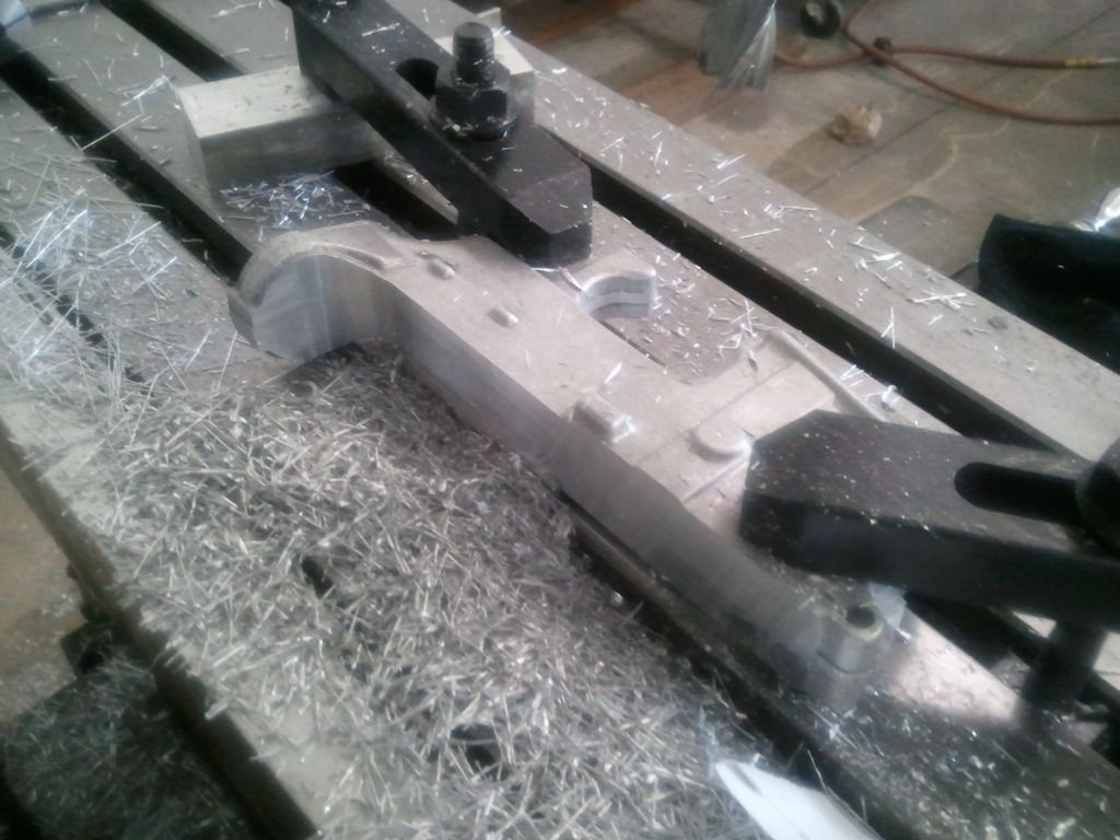 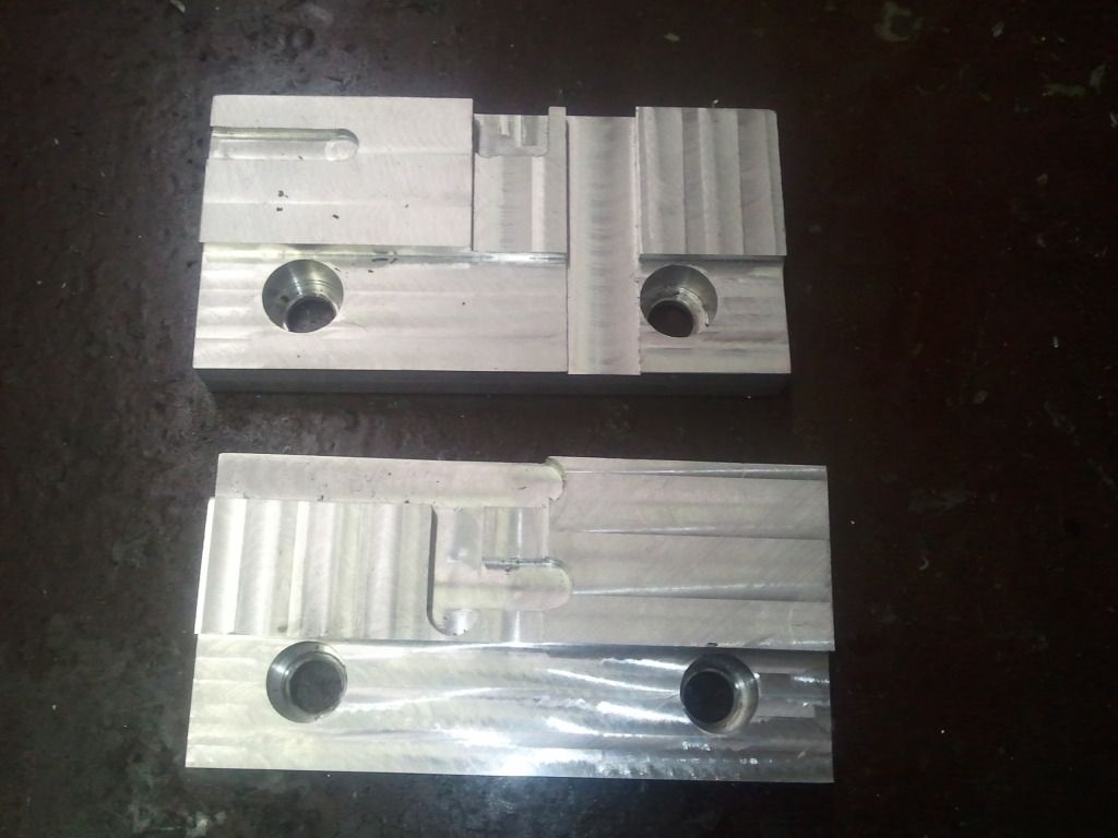  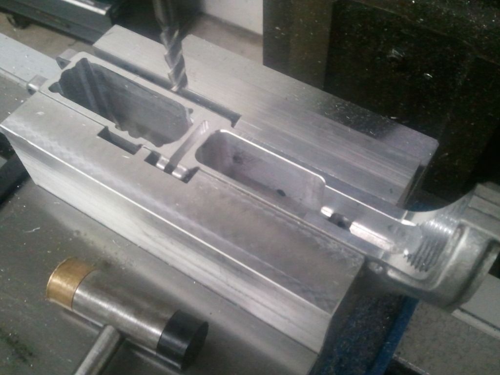 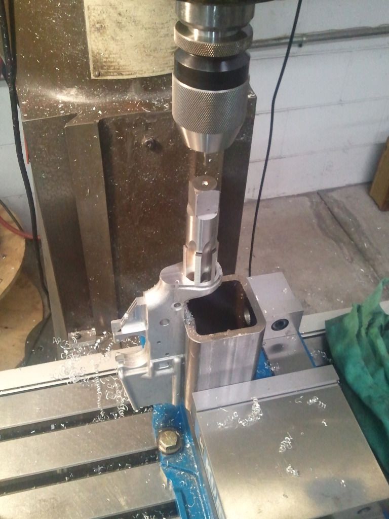 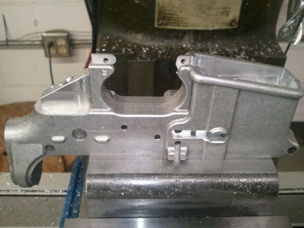 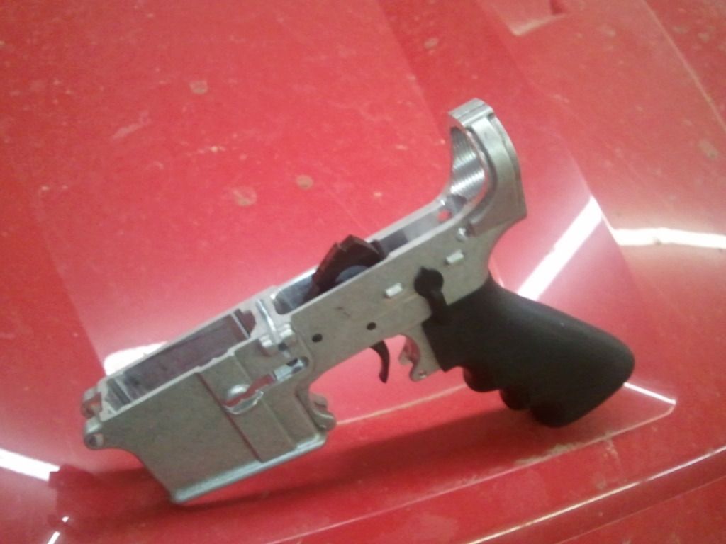 One of these days I'll file out the mag well. |
|
|
|
[#27]
Hey, we have the same Kurt D675 machine vise!
I got mine for 100 bucks with one vise jaw bolt broken off and another so overtorqued that I needed a four foot cheater bar to loosen it. After I got the bolt out, the broken off remains of the other one just screwed right out using only fingers. I had it powdercoated to more or less the original Kurt blue, and spent the whole 15 bucks that Kurt charges for a rebuild kit. It was also so chewed up on virtually every surface that I reground all the surfaces on my surface grinder. Didn't seem to do it any harm at all. But mine has no extra holes drilled in it. I hate it when people do that. Yours looks brand new. CJ |
|
|
|
[#28]
At the time it was very close to new. Yes, you can regrind this vise many times.
Posted Via AR15.Com Mobile |
|
|
|
[#29]
Quoted: At the time it was very close to new. Yes, you can remind this vise many times. Posted Via AR15.Com Mobile Remind it? What, does it forget how to be a vise?  |
|
|
|
[#30]
D'oh, telephone got me.
*regrind* Quoted:
Why can't it be as simple as dimensioning everything off of the rear takedown pin hole? A lot of the features do use this as a reference point, but others reference off the other end of the receiver or you have to add the distance from the reference point to this hole center, and then subtract the distance to another hole center, and stand on your head and stick your tongue out while closing one eye for it to all come together. In answer to this question, and I probably won't do it very well: Features are dimensioned with respect to what they interact with. Example: It is far more important for the trigger pins to be in proper proximity to each other than be the perfect height from the top deck so they (I'm doing this from memory, pardon if I'm wrong) are called out with distances from each other. I hope that makes some sense. Posted Via AR15.Com Mobile |
|
|
|
[#31]
Yeah, that makes sense, but I'd still prefer that everything is dimensioned from a single reference point, or at least, pick up the
"lead point" for any specific group of features and slave it to a single reference point. I like how you made side clamping fixtures out of soft jaws. I might extend your idea to wider soft jaws and include fixture pins for the takedown pin holes, so the lower has absolutely no chance at all of moving in the fixture. A local machine shop went out of business recently and this week they had their online bankruptcy auction. I didn't bid on anything but I did inspect the stuff in person, and noted a few things that weren't on the auction. After it was over I asked about those things, and ended up scoring a very decent Kurt vise ripoff for the princely sum of 60 bucks, as well as a free pair of Kant Twist clamps that appear to have spent about a year in the goop well of the waterjet machine. They were nasty and actually frozen from rust, but they cleaned up nicely in the media blaster. For free they're fine. Next week after the deadline has passed for the buyers to make payment, I go back and see what's left that wasn't paid for, and if it's anything I think I can even make a buck on, I'll buy it. I'm HOPING that somebody flakes on just ONE of the dozen or so Kurt vises that were in the sale. I would not mind getting one of the new style low deck D675s. Or better yet, a pair of them. It's not that I really NEED multiple vises, but if I wanted to turn out more than one lower at a time, I'd set up two vise setups on the same Y axis, spaced one foot apart on the X axis, so I can do two at a time. That'd be fun. Also, having two vises makes long work like barrel machining a lot easier. Not that I do much of that... CJ |
|
|
|
[#32]
Quoted:
Dude, use an offset boring head. Posted Via AR15.Com Mobile Boring heads are made to bore with. Using one as a fly cutter is just abuse. You can do what you want with your own equipment but if your boss caught you fly cutting with a boring head you would probably get the WHAT FOR !! real quick. Unless he don't have a clue either. |
|
|
|
[#33]
I don't have a boring head anyway.
|
|
|
|
[#34]
Quoted:
Quoted:
Dude, use an offset boring head. Boring heads are made to bore with. Using one as a fly cutter is just abuse. You can do what you want with your own equipment but if your boss caught you fly cutting with a boring head you would probably get the WHAT FOR !! real quick. Unless he don't have a clue either. You're mistaken. I'm not saying to face anything with it, but to use it to cut the receiver extension radius. That is nothing more than an interrupted bore. You seem to be in the machine trade so this should not be news to you, but there are such things as boring/facing heads. PS, of course you need two vises.  Posted Via AR15.Com Mobile |
|
|
|
[#35]
It's pretty cool that you guys machine the parts that you do. I've made a few things over the years too but after doing it all day long for a living I'd rather do something else in my spare time, like reload and shoot.
I am going to be getting into some tool grinding/sharpening soon. The guy does work for most of the local shops and said he always needs help with the work load. I've used many of his tools and he does custom work too. |
|
|
|
[#36]
Today I reground the "new" vise, using a grinder at the machine shop owned by my friend. It's a very nice
Brown & Sharpe grinder with automatic everything, and it did a great job. I reground both sides of the base, and trued up everything else. Every surface needed it. It had some saddle wear on the base, the jaw mounting surfaces were anything but flat and parallel, and I ground the hammer dents out of the top surface of the moving jaw carrier. I really wish people would not use vises as anvils. Now it needs paint. I'm thinking powdercoat, but I'll have to mask off all the appropriate surfaces very carefully. I'm still waiting for the sample waterjet machined magwell to come back. Only then will I be back on machining out a lower. Which is fine, as I do have other things I want to do anyway. I need to yank the table off the mill and rebuild the lube oil distribution system and I think that this long weekend is just right for that. CJ |
|
|
|
[#37]
When did this place turn into the KURT forum???
 |
|
|
|
[#38]
LOVE LOVE LOVE the 4".
Posted Via AR15.Com Mobile |
|
|
|
[#39]
After spending three hours using a surface grinder, I had a funny feeling in my nose.
So I grabbed a tissue and blew...and oh man! That was gnarly! Finely ground cast iron and grinding wheel dust makes for the ugliest tissue you ever saw in your life. But I feel so much better now. You may not notice it right away, but the dust settles on you and gets you dirty and you'll know it the first time you grab a towel to wipe the sweat off your face or balding head. "Hey, why's this towel suddenly the color of fresh rust?" By sheer luck, the deck height of my two reground vises is so close to the same that I'd call them matched for all but the most critical work. This "Mighty" brand Chinese made Kurt knockoff even rips off Kurt's roller thrust bearing and half sphere self aligning angle features. It's really a very decent vise. It'll hold a part. |
|
|
|
[#40]
You reground both vises, on an automatic grinder, but didn't match them?
Dude, Wtf? Posted Via AR15.Com Mobile |
|
|
|
[#41]
I reground my Kurt vise when I got it, well over a year ago.
I reground the copy when I got it, just a few days ago. I DO think that I'll match the deck heights on them, considering how close they are, probably in the next week or so. It's not like it's hard to take apart a vise. The only catch is that the grinder I can use isn't big enough for both vise bases at once. I'd prefer to match grind both at once. The best I can do is match to measured height and swap them on the mag chuck as long as they're within .001 of each other. CJ |
|
|
|
[#42]
Quoted: LOVE LOVE LOVE the 4". Posted Via AR15.Com Mobile Me too..... I forgo using a file for the mag well, and use the mill as a shaper instead. Much better control than my shaky old butter fingers and a file.  |
|
|
|
[#43]
I like that idea. I'll try it.
I've decided to take the mill down for a few days. It's finally time to rebuild the broken automatic lubrication system. I have a new(er) 1 quart capacity Bijur automatic lubricator and need to replumb virtually the whole mill with new hoses and fittings. The 6 way manifold (made of pot metal) crumbled and most of the fittings and copper piping is thrashed, so I've ordered up a new hose kit, connectors, and manifolds. I've already torn the mill down, with the table and saddle removed, cleaned up, and prepped for the new parts. I was getting tired of having to manually lube everything every day I use the mill. Automatic lubrication is a lot nicer. I'd like to set up a slow drip system for spindle lubrication as well. As this kind of mill uses a total loss spindle lubrication system, you have to be careful to keep it lubricated or the bearings are at risk of running dry, and those are expensive bearings I don't want to have to replace...AGAIN. CJ |
|
|
|
[#44]
I mentioned that a local machine shop went belly up recently, and I got a vise from them that wasn't listed in the auction.
I'd asked about other leftovers after the auction was over, and the guy running it said "Come back Friday" and that was today, so I called him on the way into work and he said "Come over now if you want anything. It'll probably all be in the dumpster by 10 AM. So I was late to work. I filled my car up with leftovers. And I was moderately picky about what I took. Some people would cry at the amount of brand new HSS lathe tool blanks I passed over, which went into the scrap metal bins. I now have several fly cutters. I scored a precision boring head that could easily cut up to 12" diameter holes using just the tool that was already in it, if set up in the outer side holes. FREE. But it has an integral R8 arbor and I don't have an R8 spindle. I take QC30 tooling. I traded this off to the owner of a local machine shop who's helping me with some lathe projects. (I don't have a lathe.) I scored a Procunier #2 reversible tapping head for 40 bucks. I think I can get a Morse #2 taper QC30 or NMTB 30 arbor...I hope. I got about six organizers full of drills, taps, reamers, center drills, counterbores, and assorted hardware. All free. Drill sizes down to #79, taps down to 0-80, sizes up to 1" for drills and taps. At least a dozen each of every tap size below 3/8-16. What looks like a complete set of all NPT taps up to 1". I've already trade or sold off the stuff I really have the least use for, or can't use at all. But what's left was well worth the cost, which was free, aside from the tapping head. I even scored a 4x8 foot sheet of 1/4" black Delrin, which will be used to make a couple of sets of way covers for the mill, one set for each vise and one set for use with my 18" rotary table. And, several gallons of assorted urethane paint that's still good, with catalyst. The flat green and semi-gloss grey will be most useful of the bunch, but I might get some use out of the bright red for painting machine guards. Not a bad day's scrounging. |
|
|
|
[#45]
If it makes you feel any better, AR10 prints are just as confusing.
Posted Via AR15.Com Mobile |
|
|

AR15.COM is the world's largest firearm community and is a gathering place for firearm enthusiasts of all types.
From hunters and military members, to competition shooters and general firearm enthusiasts, we welcome anyone who values and respects the way of the firearm.

Subscribe to our monthly Newsletter to receive firearm news, product discounts from your favorite Industry Partners, and more.
Copyright © 1996-2024 AR15.COM LLC. All Rights Reserved.
Any use of this content without express written consent is prohibited.
AR15.Com reserves the right to overwrite or replace any affiliate, commercial, or monetizable links, posted by users, with our own.