|
Posted: 8/11/2008 5:36:21 PM EDT
OK, so I've read ar-jedi's Ham Radio 101 thread and various others' posts so many times my eyes are bleeding and I've started to accumulate equipment for a portable comms box. Before I go and spend any more money, I think I need to do some planning.
I've designed my own comms box here. You'll see it's pretty close to what ar-jedi built (thanks for letting me stand on your shoulders, so to speak), but there are a few differences: use of a West Mountain Radio PWRgate to run the gear and simultaneously charge the batteries when it's connected to AC power, slightly smaller breakers (15A instead of 20A) for the loads, and a few other, mostly minor, items. Here's what I've come up with: 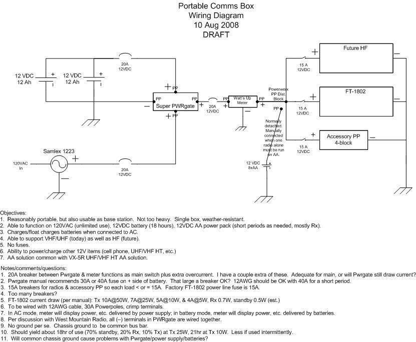 If I didn't pick the right circuit component for the diagram, well, I'm an amateur. But I now know how to use the EE tools in Visio - pretty slick once you invest the time to learn. As background, I just passed my Tech exam and am waiting for my name to appear in the FCC database. I've been working with electricity my whole life but am self-taught, so there are some definite holes in my knowledge. I picked up this ham thing with a vengeance a couple of months ago. Anyway, I've listed my objectives and a few questions and comments on the diagram. I'd like to see if anyone has any comments, suggestions, or thoughts. I'm sure there are things I haven't thought of or could be done better. One objective I omitted from the list above is the ability to communicate long-distance in the event of an extended power outage. I'll update the list to reflect this. So here are my questions: 1. Once I stepped back and looked at the bigger picture, I realized there are a lot of breakers as designed (six). Is that too many? I'm not paranoid about dirty power, but I'll have a lot of $ tied up in this, especially when I add the HF radio. I'm going to be using these breakers from Bluesea (12VDC marine breakers). As an aside, I spent a whole lot of time on hysteresis. 2. Should I/can I use larger breakers than 20A between the sources (batt, ACPS) and PWRgate? 3. Is using a 20A breaker as a main switch a good idea, just OK, or a bad idea? 4. There's no "real" ground in this thing, just a chassis ground. Is there some way to use the ground in the AC cord when plugged into AC? Or is that a bad idea? Do I even need a "real" ground? 5. The Powerwerx Watt's Up meter seems to fit my needs perfectly. Are there any other alternatives I should consider? 6. On the out side of the meter I'm planning on using this splitter with the (-) lead to chassis ground (not listed in diagram). Anything else out there with PP I should look at? 7. With the chassis ground on the ACPS/batteries/PWRgate I worry about a ground loop. Am I missing anything. Thanks. |
|
|
|
[#1]
TAG!
This will be some great info for when I put together my comms box in the future. |
|
|
|
[#2]
you can delete the breaker between the PWRgate and meter. i don't think that's doing anything for you. i also think you should up the "Future HF" breaker to 20A (or 25A). you will be hard pressed to find a 100W HF rig that does not draw a tad over 20A. you'll have to remember to keep the TX power dialed down otherwise.
see above. the samlex 1223 makes 23A continuous -- you *may* likely need that depending on which HF radio you pick.
i think, as noted above, it's redundant. the way i set up my rocker switch, with center off, does perform a "master switch" function -- with it off i know power isn't going anywhere. in your case even with the subject breaker off, you still have the batteries charging from the AC power supply.
i don't know whether the 1223's output is floating or not. i have to look it up. if it's floating you could tie GND to the chassis, and be done with it. that would also provide a safety ground in case there is a fault with the AC wiring internal to the box.
IMHO this is an excellent instrument for this application. it will do exactly what you need it to do.
that will do it.
yes, all the grounds should be in one place. i would tie GND to the chassis at the power supply ONLY, or tie all of the grounds to a ground block and then over to the power supply. i just measured my 1223's outputs and they are floating. use a ground block of some type, and bring all of the GND wires there. i'm going to throw you one more curveball... many modern consumer electronics recharge via USB cables (e.g. my Moto cellphone and it's Bluetooth headset). if you incorporate a 12Vdc -> 5Vdc converter, and make provisions for connecting to the world, it will save you from having to carry around a bulky adapter. here is the converter i currently have with the box: www.dealextreme.com/details.dx/sku.12210 -- with that converter and a cigar lighter receptacle with a PP on it, i can charge my phone etc using just the USB cable. what i will eventually do is mount the internals of the converter inside my box (for $4.99 with FREE SHIPPING you can't go wrong here). ar-jedi |
||||||||
|
|
|
[#3]
I concur with jedi. I think you've made some good choices. I'll probably be adding a similar PP block to my comm box and while the WhattMeter was in the initial design I've had a hard time breaking the funds out of my wallet.
My only real concern is the power rating of the batteries. I supposes it's not too much of an issue since you can always replace them. However, I'd rather buy once. I haven't done any exhaustive research (ok, I've done very little) but I'd say a safe guess for your future HF rig would be about 20A Tx and 2-2.5A Rx. You might want to take that into consideration before you decide on which batteries to add. Ok, thinking about it more, have you already picked up the 1802? |
|
|
|
[#4]
OK, here's a redesign based on the comments above:
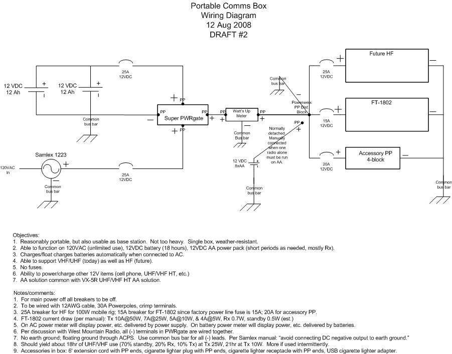 I've kept the first version up so readers could see the progression & correction of a few symbols.
Done, & done. 25A breakers & 12AWG wire should be OK for short periods, right (e.g. time lag between overload and breaker trip)? If my research is correct 12AWG should be able to handle up to 47A as chassis wiring.
For main power off, I'll just turn off all the breakers. That should take about half a second, and I don't think I need a rocker switch the way this is wired.
On this one I admit to some confusion. What you're suggesting, if I understand correctly, is to bring all the neg (-) leads to a grounding block, including the neg (-) from the ACPS. This will provide a floating ground. The ACPS manual is pretty specific about not connecting the neg leads to the chassis, since the chassis is connected to an earth ground (e.g. the third pin on the AC cord). In thinking about this, there won't be an earth ground in the system since nothing will be physically connected to an earth ground - except internal to the PS itself. Is that correct? What if I'm operating the radio standing on damp grass?
I don't have any devices that charge USB-only now, but others may, and I may in the future. I can swing the $5 & will probably pick up a couple. I've also added a few accessories to the box, as you'll see in comment #9 in the diagram.
As to batteries, the 12V 12Ah were reasonably cheap at $30/ea. They're sealed Powersonic AGMs - part no. PS12120F2 here. Battery specs are available in this pdf. I can upgrade later if I find I need to. Since these batteries are 18lb together, once I add the weight of the radio gear, power supply, antennas, accessories, etc. I'd expect to be pushing 30lb. For me that's fine, but if my wife needs to carry it I don't want to get too heavy. Larger capacity batteries would push the weight up significantly. 18Ah batteries add at least another 8 lbs total to the box and are significantly larger. 100W Tx on HF would only give me about 6 hours of battery life, so I'll clearly need to be cautious about transmission habits on battery power.
Yes, I picked it up for pretty cheap ($130, shipped free). For the $20 or so I would have saved on a used unit it wasn't worth it. I'm looking forward to building this thing. Thanks for the comments so far. I'd appreciate another review! |
||||||
|
|
|
[#5]
I'm familiar with the Powersonic batteries. That's what powers my box. As long as you realize the impact the HF will have on your power consumption I'm happy. Fyi I have a 55AH Optima yellow top that goes with me if I'm deployed to a shelter or hospital. Of course, it's really not needed as I have critical power available to me at both location types. Of course, there's always the chance the generators won't work, so the battery goes.
Good enough. I'll just put the bug in your ear about eventually looking at a dual-Rx radio so you can monitor/scan on one side while talking on the other. Forgot to mention before that I think you're doing well planning on being able to charge other devices. I've had to charge my HT from the battery in the comm box. It's nice to be able to do something like that. It's not always feasible to charge something in the vehicle. If yours is like my truck no engine running = no juice to the outlets. |
||
|
|
|
[#6]
I figure if the SHTF hits the fan I'll either be at home where I can pull out one or both car batteries or on the road where I'll likely be near a vehicle, either mine or someone else's. I have a set of battery clips like this one on which I've cut off the receptacle & installed PP ends, so I can just clip onto the car battery and replace the lead from the sealed batteries with the car battery (harder to explain that it is to do). I'll still have the benefit of the PWRgate, etc. in the box. Having a spare 55Ah battery would be nice, though...how much do those run?
I thought about a dual bander (2m/70cm), but the 1802 was cheaper by about $130, which for now funded the power supply and a few other things. As I get more sophisticated I'll be better able to determine what I want, and if I decide to upgrade to a dual band I can likely sell the 1802 for about $100 - only a small loss. Or maybe do my first mobile install. Plus I have a VX5R HT tribander that I'd likely have with me, though it's only 5W on Tx. The next radio I get will be more sophisticated, likely HF + UHF/VHF.
I guess I don't remember if there's power if the engine's off. I'll have to check. Thanks for the hint. |
|||
|
|
|
[#7]
6530, your inbox is full. Trying to send you an IM.
|
|
|
|
[#8]
Cleared out. Sorry 'bout that. |
|
|
|
|
[#9]
25A and 12AWG for the lengths that you have will be fine. for 47A, 12AWG would not be my recommendation. that's a lot of current for 12AWG, and you would likely find significant heating.
that recommendation in the manual is there as part of a section on helping isolate RF noise generated by the switching circuit from the output DC wiring. that said, i would suggest using a common bonding bar to tie together the negative DC lead, all negative leads from the radios, and finally the AC safety ground (green wire ground). i believe that this is exactly what you have already shown in your diagram. should you have any kind of RF noise problem, you can first try to float the power supply. i doubt you will need to do this. an easy way to A/B the noise is to switch between battery operation (no noise) and power supply operation (maybe some noise). if there is any effect on the radio(s) (especially the HF rig) you know you have some work to do. in my case, my Samlex 1223 and the way that i have it wired have caused no problems.
connect the safety (green wire) ground to everything metallic. this will help prevent you from getting a shock in the event that there is a wiring fault or the 1223 fails catastrophically internally. in the case of my box, i mounted the metal-cased IEC320 power filter to the switch/meter bracket, and carried the green wire ground through to the SEC1223 power supply. the bracket itself mounts the ground bus bar, so all is tied together. i recommend that you use an input power filter as well, you should be able to pick one up for around $5 or so. ps: i took some time off calibrating my new (used) Icom IC-706MkIIG to take some pics of an example IEC320 AC input power filter, which shows how the ground tab is electrically connected to the metal housing. ar-jedi         |
|||
|
|
|
[#10]
I wouldn't ever expect to see 47A in this setup, so I thought I'd be OK. Thanks for the confirmation.
OK, now I understand. That's what I'll do. Earth ground to the power supply, bus bar, and other metallic components. I don't have access to CAD/punch/brake, so for purposes of my panel I'm going to have to follow an alternative approach. I'm thinking some sort of 1/8" polyethylene or polypropylene (cheap, readily available locally, easy to drill/work, and weldable). Maybe somethng like this. My electrical connections will be different that what you've pictured.
Would this be something I can pick up at a local electronic supply shop? I'm planning to buy several other components from Mouser, but if I can get the filter locally I'd prefer to do that.
These are very helpful, thanks. BTW, I found a $5 dual USB charger at Wally World. |
||||
|
|
|
[#11]
take a look at this method of construction: www.eham.net/articles/17836
Mouser will have them; i don't know what local shops will. you need one with an input current rating of about 5A (or more). ar-jedi |
||
|
|
|
[#12]
Great, thanks for all the help ar-jedi. Now to go build...
|
|
|
|
[#13]
I just posted in this thread a partial list of parts and tooling for my box.
There are also a few other items that I'm using that are not listed in that thread: Bluesea 12VDC circut breakers that combine switching & overcurrent protection. West Mountain Radio Super PWRgate to keep batteries charged while powered by AC. When I shut the box down I will shut off all breakers, thereby ensuring that there's no battery draw & no drain while the box is unplugged. Various RF adapters. Red-Dee power splitter. OEM adapter cable. |
|
|
|
[#14]
Quoted:
Great, thanks for all the help ar-jedi. Now to go build... any updates? as they say over in GD ––> "pics or it didn't happen" ... ar-jedi |
|
|
|
[#15]
Unfortunately this project isn't as far along as I'd like. I've bought all the components but haven't yet built the frame for inside the box. I've been distracted by various other activities, including a installing an FT-857/ATAS 120 in my car (my first mobile install) - I'm not done with that yet either.
Anyway, when I dry fit the components in the box I did run across a few challenges. It seems that the 857 is physically longer than the IC-706, so rather than hang the radio from the top of the box I'm going to have to mount it on the bottom. Due to the way the top of the box is molded, there are reinforcing ribs that would interfere with the faceplate of the radio were it to be mounted from the top. In addition, because of the length of the 857, depending on the thickness of the power supply plus the PWRGate, and taking into account the thickness of the frame, I may also have to mount one or both upside down behind the panel. I plan to rough out a sample frame in wood before putting the final version together with 1/2" or 3/4" square aluminum channel. The idea is that the radio, batteries, etc. will be mounted to a "floating" frame that will slip inside the box and can be removed if necessary. One of my design objectives is no holes in the box. I've also designed a panel that I have to measure for final sizing. I used free software from Front Panel Express. The software's pretty slick and is integrated with their manufacturing processes - you send in a file from the software and they send you a completed panel. The panels aren't cheap, but the company appears to have a great reputation for good work. You have a choice of materials, finishes, holes, engraving, and various other options. I've printed out an actual-size version of the panel and have cut out the holes with an Xacto knife to make sure my design will work. This has turned out to be more complex than I expected...as it seems everything I do is  . .
|
|
|
|
[#16]
Let me know if you want to get together to work on anything. I think your best option to the sizing problem is to give me the 857 and buy yourself something smaller.
|
|
|
|
[#17]
Quoted:
Quoted:
Great, thanks for all the help ar-jedi. Now to go build... any updates? as they say over in GD ––> "pics or it didn't happen" ... pics? ar-jedi |
|
|
|
[#18]
Quoted:
TAG! This will be some great info for when I put together my comms box in the future. TAG for me, too! Great documentation 6530! I'm in the process of building a similar portable comm box and you have some nice additions/options to ar-jedi's design I have been basing mine on. Can't wait for some pics. |
|
|
|
[#19]
Double tap, sorry.
|
|
|
 Win a FREE Membership!
Sign up for the ARFCOM weekly newsletter and be entered to win a free ARFCOM membership. One new winner* is announced every week!
You will receive an email every Friday morning featuring the latest chatter from the hottest topics, breaking news surrounding legislation, as well as exclusive deals only available to ARFCOM email subscribers.

AR15.COM is the world's largest firearm community and is a gathering place for firearm enthusiasts of all types.
From hunters and military members, to competition shooters and general firearm enthusiasts, we welcome anyone who values and respects the way of the firearm.

Subscribe to our monthly Newsletter to receive firearm news, product discounts from your favorite Industry Partners, and more.
Copyright © 1996-2024 AR15.COM LLC. All Rights Reserved.
Any use of this content without express written consent is prohibited.
AR15.Com reserves the right to overwrite or replace any affiliate, commercial, or monetizable links, posted by users, with our own.