|
Posted: 5/16/2016 1:17:41 AM EDT
And here we go!
 The first thing I do is take pics, sit back and have a cold one, and then take more pics. Once that is done I take even more pics. You will want a LOT of pics to fall back on and even then you may not have enough. So here we go. 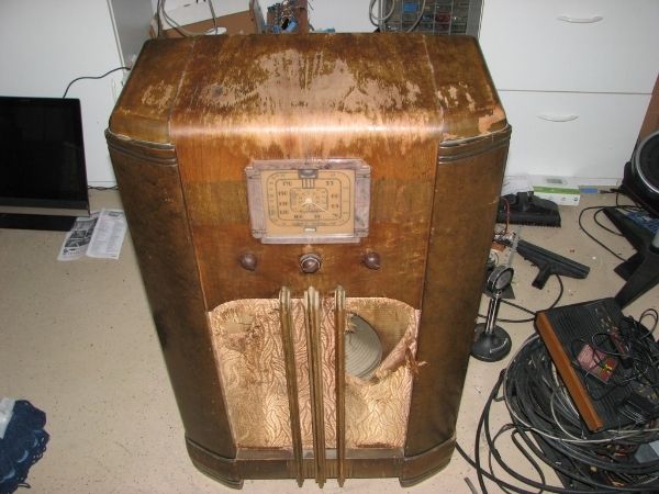 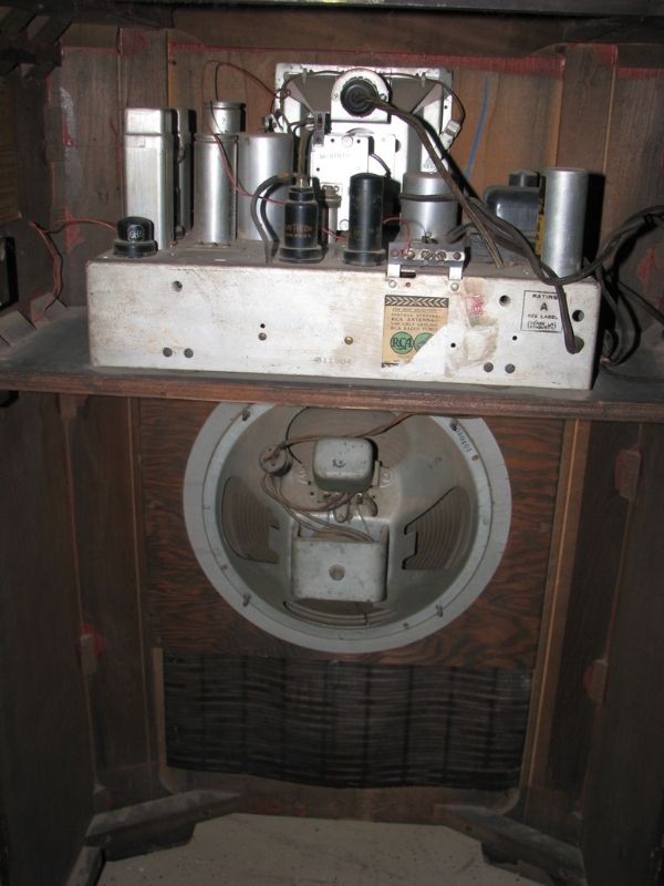 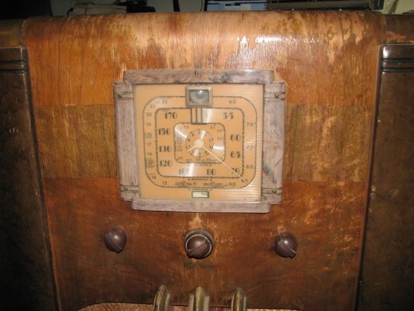 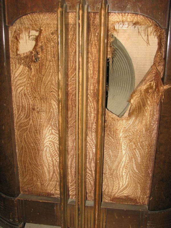 I think you get the idea so I wont bore you with all the pics. |
|
|
|
[#1]
Tag.
|
|
|
|
[#2]
Man, that one is in rough shape! Can't wait to see what you do with it
|
|
|
|
[#3]
Wait until you see the dust in this thing.
Jimmy Hoffa might even be underneath all this crap |
|
|
|
[#4]
Quoted:
Wait until you see the dust in this thing. Jimmy Hoffa might even be underneath all this crap Make sure you stir it up real well and take a deep breath 
|
|
|
|
[#5]
Looks like another nice project.
|
|
|
|
[#6]
I have a bad feeling that those two columns on the sides are photo finish.
I cannot STAND photo finish It's pretty much simulated wood grain stuck onto some crap wood. Pray for me |
|
|
|
[#7]

How many console radios are you up to now?
|
|
|
|
[#8]
Quoted: How many console radios are you up to now? 2 I kept 1 Given to a friend Last one about to be given to another friend This one has the Magic Eye...I'm keeping this bitch! So this is the 5th I've worked on. |
|
|
|
[#9]
Took the knobs off and spotted a couple of things.
Left pot looks ok, middle pot you can see the busted belt that drives the gears and the right pot is not original. It has been cut to size and molded to fit. I'll have to see if it is audio tapered since it is the Volume control. 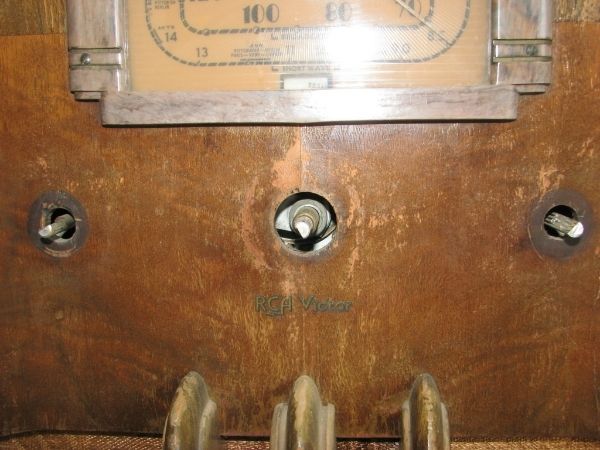 |
|
|
|
[#10]
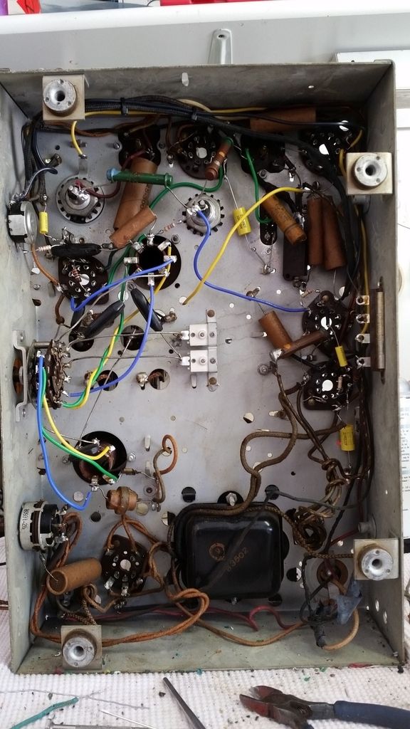
Chassis removed from cabinet. Just a little dust
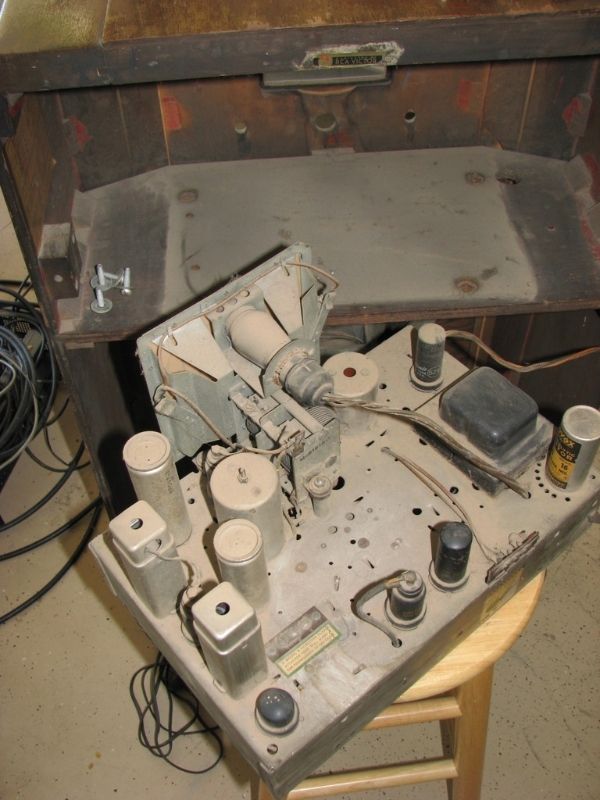 Got it up on the bench. Now we can really take a look at what we have here. I can see it is missing left/center dial plate retaining pins. Looks like it used to have one due to the coloring differences where the head would have been. 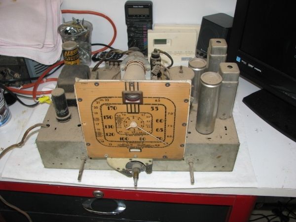 That back left Aerovox electrolytic capacitor (yellow sticker) is not original but I don't mind that at all. I leave the old ones in disconnected and put the new ones underneath. Keeps the top looking more original. 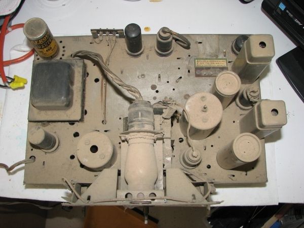 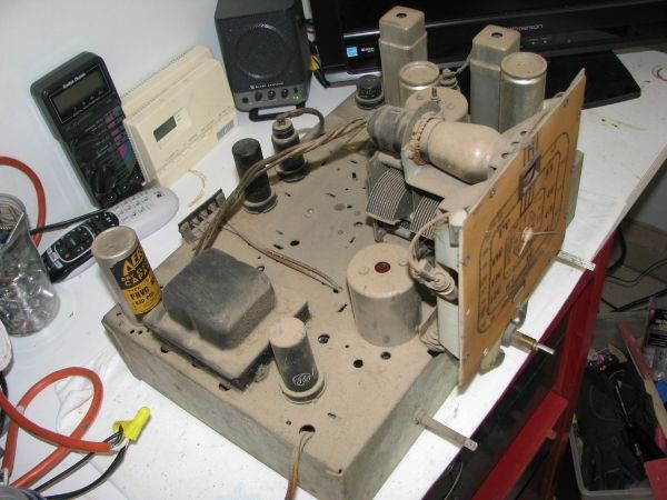 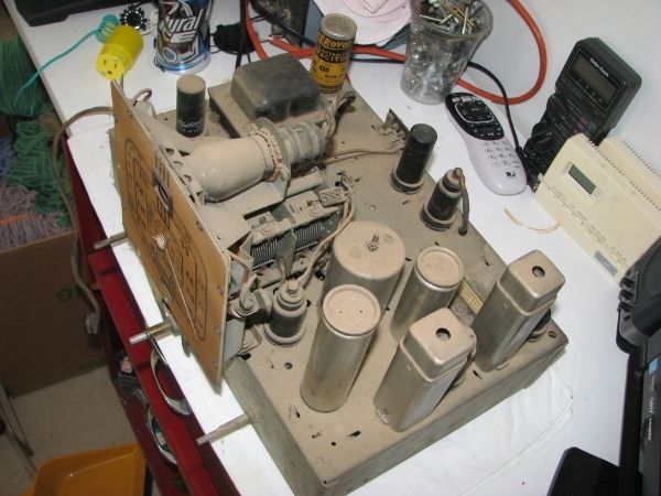 Magic Eye is one dusty tube. That grommet is a disaster. Will have to look into getting a replacement. 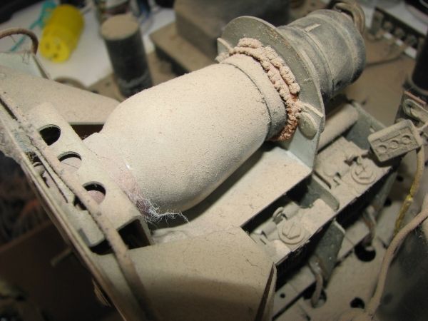 Soon we'll take a look under the hood. |
|
|
|
[#11]
I spy an Atari. I still have mine as well, my friend stole all my games though.
|
|
|
|
[#12]
Quoted: I spy an Atari. I still have mine as well, my friend stole all my games though. Yup. I have a variety of toys laying around ;) |
|
|
|
[#13]
Close up of the dial. The needles will need to be painted.
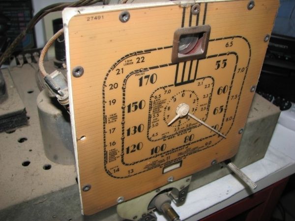 Close up of dust and rotted wiring 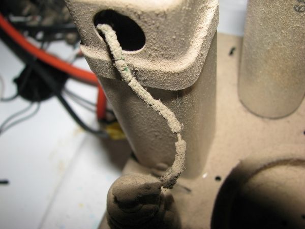 Dusty tuning capacitor 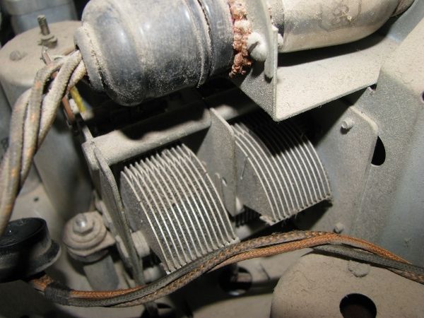 Underneath the chassis. WOW! This looks to be the easiest I have tackled yet. 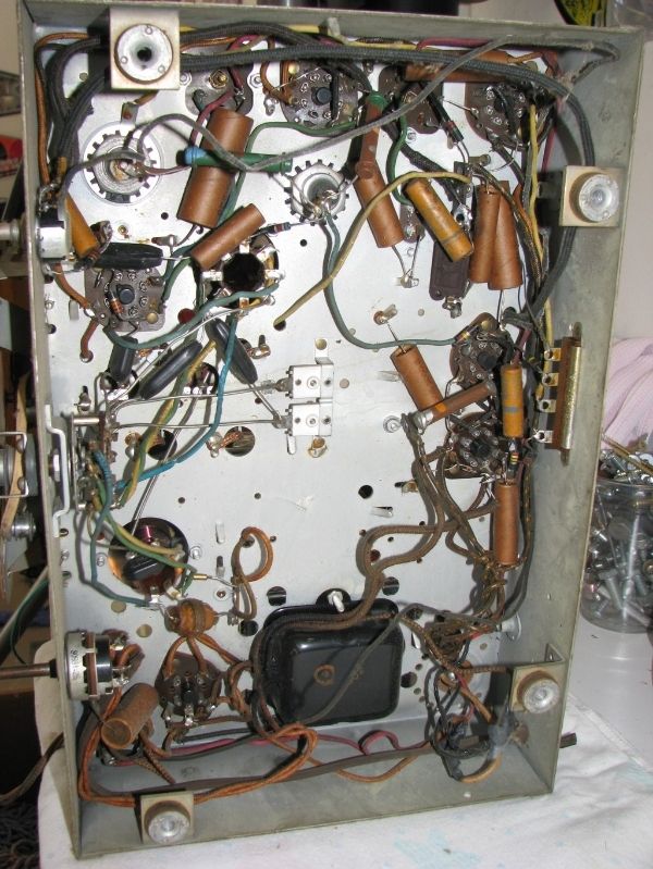 |
|
|
|
[#14]
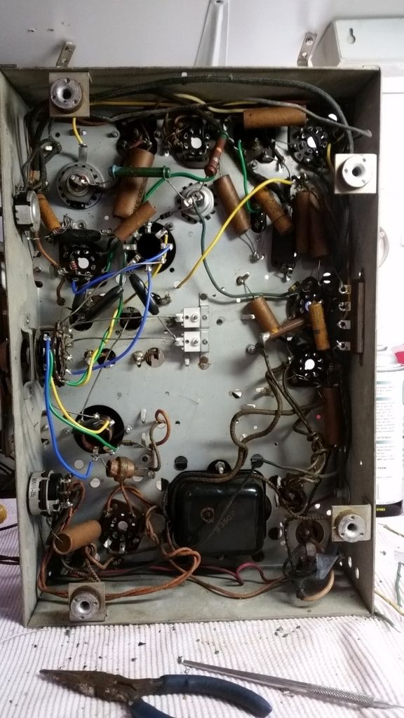
I did take the unit outside and brushed it down a bit to get most of the dust off. I don't want to be working with a completely nasty chassis.
Here is the schematic we'll be working with for this radio. Red circle is the power transformer and it's what I want to ohm out first to see if it's ok. In the above pic it's the black box center/bottom. You can view close up here - http://www.nostalgiaair.org/pagesbymodel/182/M0015182.pdf |
|
|
|
[#15]
I ohmed out the power transformer circled in red above.
Primary winding Expected/Actual 8.4 ohms / 8.7 ohms Secondary winding Expected/Actual 775 ohms / 796 ohms It's a start. Looks like the PT is probably ok. I do believe that the person I got it from did say they powered the unit up but didn't receive any signals. So they kind of already tested the PS for me. Now I am not going to power it up until I get the capacitors replaced but at least we know this much.
|
|
|
|
[#16]
In for the frequency of updates...
|
|
|
|
[#17]
Checked the I.F. Transformers out. As you can see expected value is 7.2ohms for all points.
Lets zoom in a bit 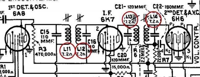 L11 = 7.4 ohm L12 = 7.3 ohm L13 = 7.4 ohm L14 = 7.2 ohm So far so good there as well |
|
|
|
[#18]
Also checked out the field coil. Meter read 1293 ohms so this appear ok 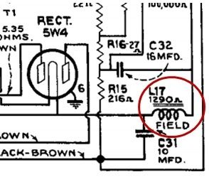 |
|
|
|
[#19]
While taking some readings the dirty band switch just had to get cleaned.
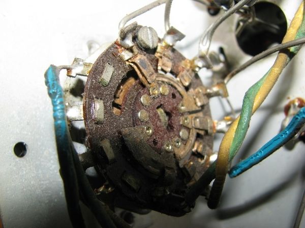 It will get some more cleaning later on but this is much better. 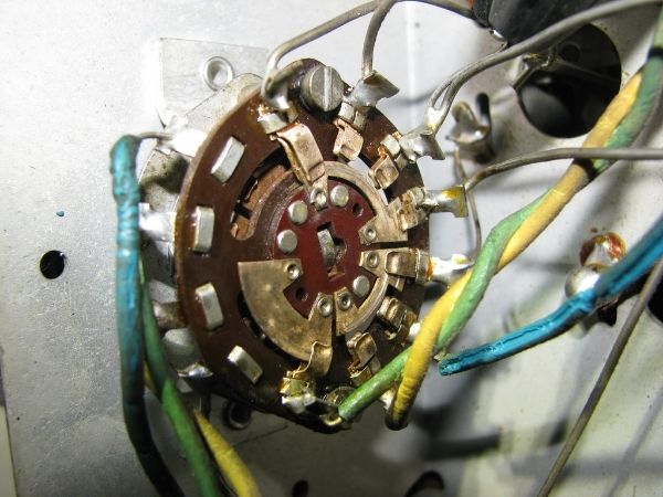 I have to take note of those twisted wires. That may be what is called a "gimmick" capacitor. It is used when a very small amount of capacitance is needed. When I rewire it I will be putting them back the same way so I should be fine. I'll have to see if they call this out on the schematic. |
|
|
|
[#20]
Checked out the speaker connections today.
This area here 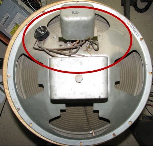 Schematic 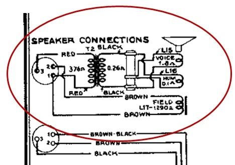 T2 Primary Expected/Actual 376 / 416 ohms T2 Secondary Expected/Actual .26 / .3 ohms L15 Expected/Actual 1.8 / 1.4 ohms L16 Expected/Actual .1 / .2 ohms Field Coil we already did above Looks like things are continuing to check out for the best. |
|
|
|
[#21]
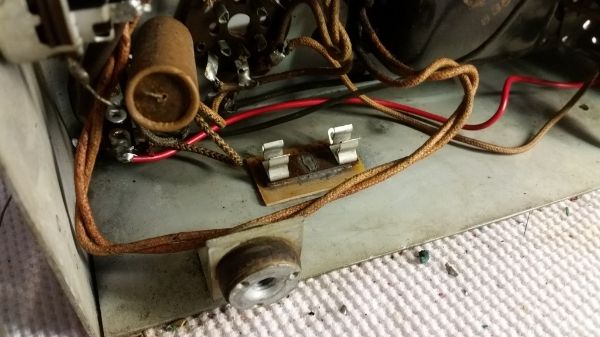
So I thought I'd get a fuse holder ready to install. These units have no fuses in them. I tend to use what I have on hand before I spend money so I rigged this up. It's a fuse holder that had bottom leads poking out of it. I bent them down and mounted onto a PCB. In this pic you can see I JB welded it to the PCB. I can't have the bottom contacting the radio chassis. I will then JB weld it onto the inner wall of the chassis. The JB weld going into the PCB holes and into that center hole of the holder should lock it in place. You can see center of holder where I spread it out to help lock it in. 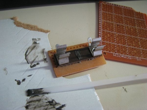 |
|
|
|
[#22]
What were those "Magic Eye" devices? What/how were they used?
|
|
|
|
[#23]
Quoted: What were those "Magic Eye" devices? What/how were they used? It is a visual tuning aid. The closer the green circle comes together the more in tune you are Kind of like this one although there are different types 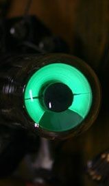 |
|
|
|
[#24]
I had one of those on an old L,R, C meter. That was so long ago, I'd forgotten about it until I saw the photo.
|
|
|
|
[#25]
Found this little gem the other day.
This wire, like others, is rotting and it is rotting right into that part of the chassis. It is not currently shorted to the chassis but WOW is that close. 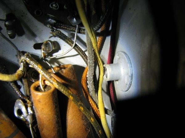 Cleaned the tubes in preparation for testing. 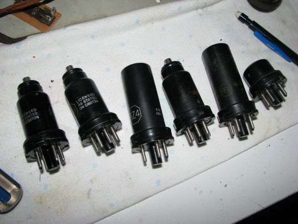 All tubes tested fine except the 6F6. Not looking to hot but I am going to see how well it performs when we get to that point. 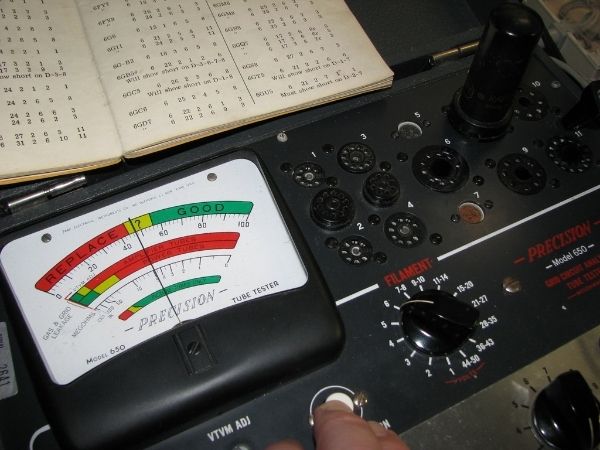 |
|
|
|
[#26]
Good work! Keep updating this thread as I love Magic Eye tubes.
I've got to drag the Halli SX-110 onto the bench for a Magic Eye "accessory". I have all the parts including a matching case but it's just one of "those" projects. |
|
|
|
[#27]
Ordered replacement capacitors the other night.
In the meantime I'll start working on replacing the old wiring. I also have to figure out if I am going to try and get into the IF cans or leave them for now. I think these have to be completely removed from the circuit to open them. Not to excited about that if that is the case. |
|
|
|
[#28]
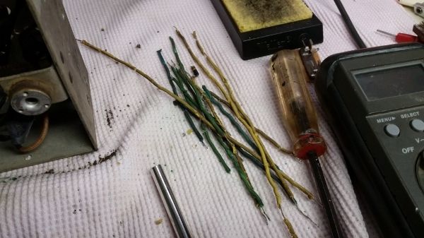
Time to replace some rotting wires
Let's start with this beauty 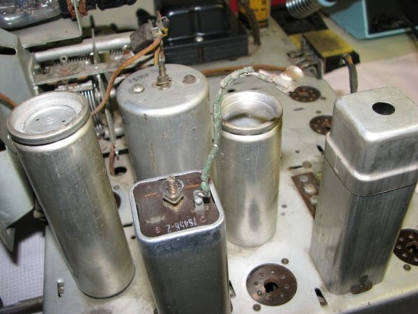 Now that is much better 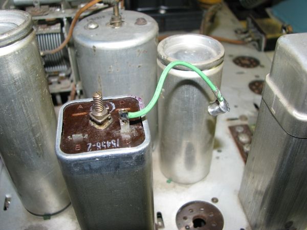 Here we tackle the band switch wires and a couple of others Before 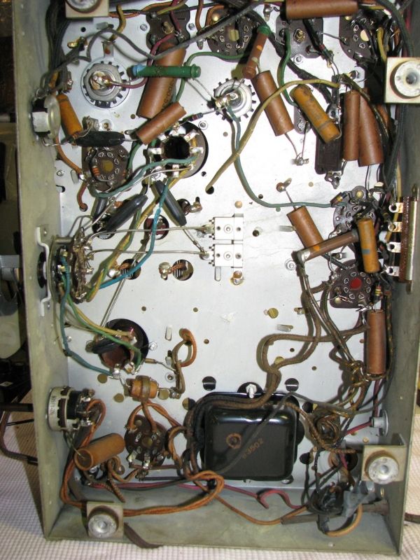 After 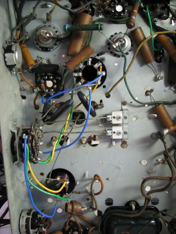 More to come |
|
|
|
[#29]
Nice collection of old rotting wire
  |
|
|
|
[#30]
Quoted:
Nice collection of old rotting wire
http://i1289.photobucket.com/albums/b519/Edisla/Mobile%20Uploads/20160528_145443_zps9ox7ggs7.jpg Do they smell like asbestos?
|
|
|
|
[#31]
Quoted: Do they smell like asbestos? Quoted: Quoted: Nice collection of old rotting wire http://i1289.photobucket.com/albums/b519/Edisla/Mobile%20Uploads/20160528_145443_zps9ox7ggs7.jpg Do they smell like asbestos? No but taste like it |
|
|
|
[#32]
Did some more rewiring. Not sure you can tell but whatever
 Did some work on the top as well. New resistor and wires. 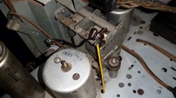 |
|
|
|
[#33]
In that last photo, the wire looks taught. That's bad. Add some slack for stress relief.
Also, it is going thru an uninsulated hole in the chassis (passing over a "knife" edge). That's bad, too. Is the wire double insulated? Add a grommet or a sleeve or spot bonds. |
|
|
|
[#34]
Quoted:
In that last photo, the wire looks taught. That's bad. Add some slack for stress relief. Also, it is going thru an uninsulated hole in the chassis (passing over a "knife" edge). That's bad, too. Is the wire double insulated? Add a grommet or a sleeve or spot bonds. It should definitely get a grommet for safety, but you can see the rest of that wire under the chassis and there's no tension on it |
|
|
|
[#35]
One thing that has changed significantly and for the better is how we wire things.
That thing looks like it was built by an untrained, high schooler building their first kit. I wonder who laid out the chassis and what their thoughts were on placement and wiring. It seems like just so much spaghetti. |
|
|
|
[#36]
Quoted: It should definitely get a grommet for safety, but you can see the rest of that wire under the chassis and there's no tension on it Quoted: Quoted: In that last photo, the wire looks taught. That's bad. Add some slack for stress relief. Also, it is going thru an uninsulated hole in the chassis (passing over a "knife" edge). That's bad, too. Is the wire double insulated? Add a grommet or a sleeve or spot bonds. It should definitely get a grommet for safety, but you can see the rest of that wire under the chassis and there's no tension on it If I find grommet laying around I might put it in but I'm not to worried about it. If this was a piece of equipment that was going mobile I would certainly put a grommet there. I figure if it didn't short out in the last 80 years it probably wont in the time I have it |
|
|
|
[#37]
Quoted:
If I find grommet laying around I might put it in but I'm not to worried about it. If this was a piece of equipment that was going mobile I would certainly put a grommet there. I figure if it didn't short out in the last 80 years it probably wont in the time I have it Quoted:
Quoted:
Quoted:
In that last photo, the wire looks taught. That's bad. Add some slack for stress relief. Also, it is going thru an uninsulated hole in the chassis (passing over a "knife" edge). That's bad, too. Is the wire double insulated? Add a grommet or a sleeve or spot bonds. It should definitely get a grommet for safety, but you can see the rest of that wire under the chassis and there's no tension on it If I find grommet laying around I might put it in but I'm not to worried about it. If this was a piece of equipment that was going mobile I would certainly put a grommet there. I figure if it didn't short out in the last 80 years it probably wont in the time I have it I think the cloth insulated wire would be a little less prone to get a cut in the insulation as compared to modern wire. It's also possible that there was originally a grommet there but it rotted away. |
|
|
|
[#38]
A little dab of silicone adhesive (a dielectric) will stop it from ever rubbing the edge.
|
|
|
|
[#39]
Replaced some more wiring and started replacing some out of tolerance resistors. I also found a couple caps I had on hand so I replaced a few.
 |
|
|
|
[#40]
Some more wiring and replaced a couple dogbone resistors
 |
|
|
|
[#41]
Still waiting on parts.
New roll of solder did arrive today. I was just about out It has also been like 100 and death in the garage so not really wanting to sit in that. |
|
|
|
[#42]
I did install the fuse holder the other day so at least something got done
 It also hit me that I did not test the Magic Eye so I fired up the tube tester. When I went to put the tube in for testing I found out it doesn't test that tube I need a get a tester with more options. We'll have to wait to see how it looks when we fire the unit up. |
|
|
|
[#43]
Decided to clean the knobs today.
Before 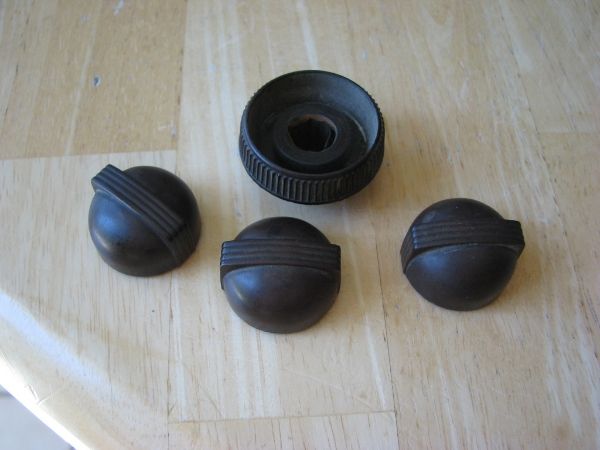 Put them in a mug of windex and hot water. Why that combo? No idea they were just handy  Here is how the water looked after sitting for a few and a little swirling around. 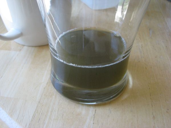 How they looked after a little brushing and then drying. They come out looking dull. 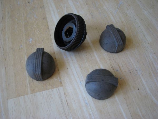 After They look better after a little oil is applied 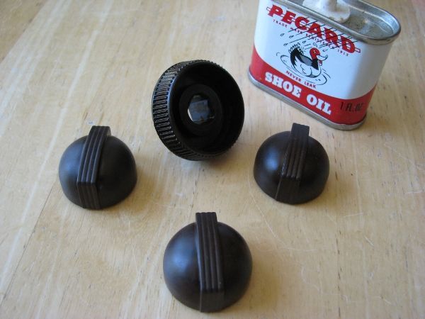 That's all for now. |
|
|
|
[#44]
I noticed that the tuning knob had a broken piece on the shim that sits inside. It butts up to the high side of the shaft to keep it from going all the way down.
Wait...did I just say that? Anyway I took an auto body shim and cut a small piece to put in there and it seems to be working. I'll double check and then glue into place if it is ok. Here is the shaft. 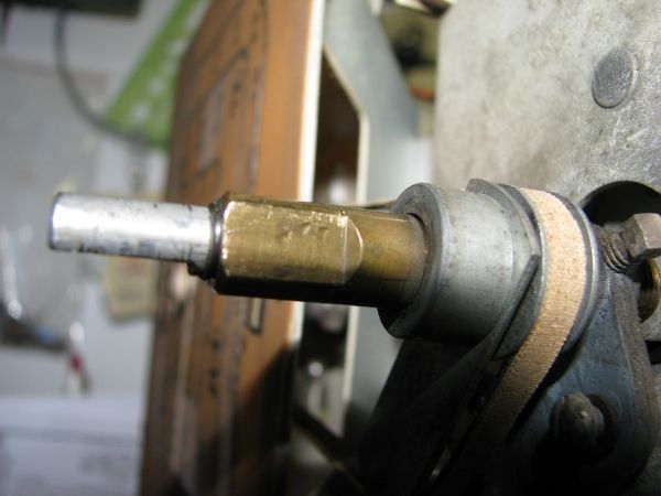 And here is the new piece and the shim I cut it from. The new piece is the upper right shinier piece. If you can't tell I'll try and get a better pic of what is going on here. 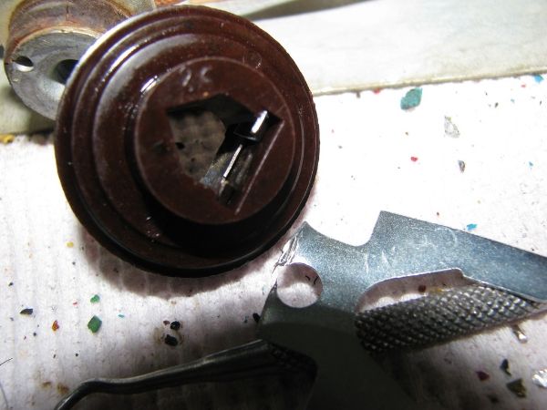 |
|
|
|
[#45]
Still waiting on parts. They come from Canada and usually take 2 weeks
If nothing by Saturday I may start working on the cabinet. |
|
|
|
[#46]
Took off the escutcheon and started to take a look at the veneer.
Here you can see above the tuning knob some loose bulging veneer. 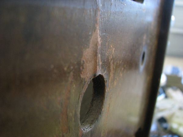 Once I started looking at things I noticed that inside of the above bulge was more separation (black gap center left). 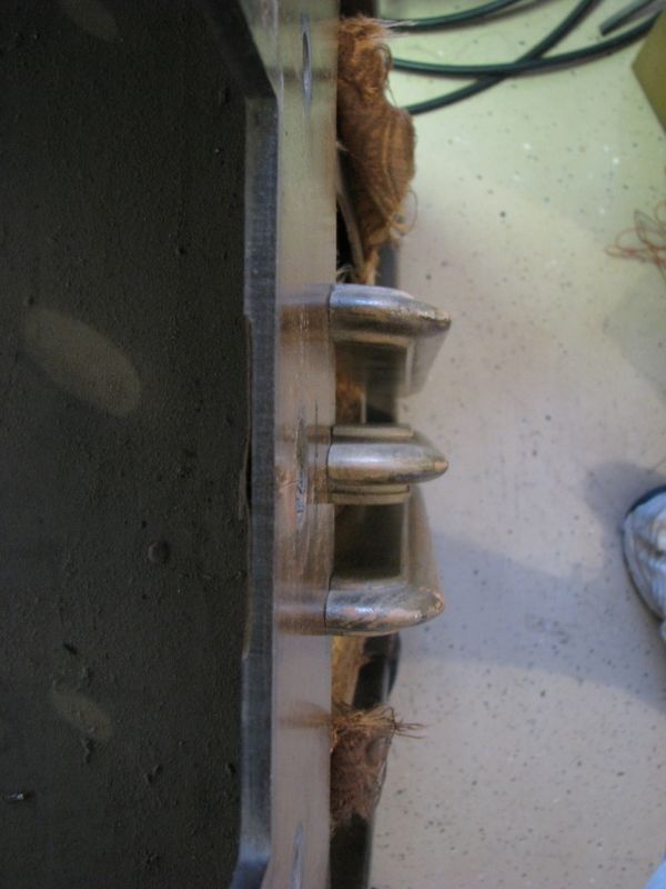 Looks like we get to tackle both at the same time |
|
|
|
[#47]
Quoted:
Decided to clean the knobs today. Before http://i1289.photobucket.com/albums/b519/Edisla/IMG_3447_zpsp2tvuc1g.jpg Put them in a mug of windex and hot water. Why that combo? No idea they were just handy
http://i1289.photobucket.com/albums/b519/Edisla/IMG_3449_zpsc7bomqf5.jpg Here is how the water looked after sitting for a few and a little swirling around. http://i1289.photobucket.com/albums/b519/Edisla/IMG_3451_zpscrds5b1q.jpg How they looked after a little brushing and then drying. They come out looking dull. http://i1289.photobucket.com/albums/b519/Edisla/IMG_3450_zpsy6hcz8lm.jpg After They look better after a little oil is applied http://i1289.photobucket.com/albums/b519/Edisla/IMG_3455_zps0hewgk23.jpg That's all for now. I hate to say it, but the before and after pics of the knobs look nearly identical
|
|
|
|
[#48]
I hate to say it, but the before and after pics of the knobs look nearly identical That's ok because at least now they are not covered in 80 years of dead skin and nicotine |
|
|
|
[#49]
I got a better look at the tuning knob mod I did and found it was not good enough.
The original did not have just 2 out segments but a middle as well. I made a solid unit out of a piece of shim as you can see here. 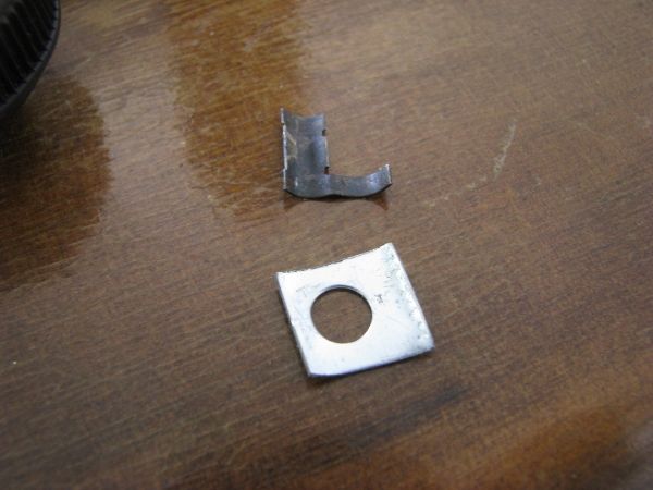 Seems MUCH better 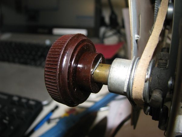 |
|
|
|
[#50]
Quoted:
It is a visual tuning aid. The closer the green circle comes together the more in tune you are Kind of like this one although there are different types http://i1289.photobucket.com/albums/b519/Edisla/magiceye_zpspumpd2sw.jpg Quoted:
Quoted:
What were those "Magic Eye" devices? What/how were they used? It is a visual tuning aid. The closer the green circle comes together the more in tune you are Kind of like this one although there are different types http://i1289.photobucket.com/albums/b519/Edisla/magiceye_zpspumpd2sw.jpg So that's what that is. My Dad had a reel to reel tape recorder that had one of those on it. Vulcan94 |
|
|
 Win a FREE Membership!
Sign up for the ARFCOM weekly newsletter and be entered to win a free ARFCOM membership. One new winner* is announced every week!
You will receive an email every Friday morning featuring the latest chatter from the hottest topics, breaking news surrounding legislation, as well as exclusive deals only available to ARFCOM email subscribers.

AR15.COM is the world's largest firearm community and is a gathering place for firearm enthusiasts of all types.
From hunters and military members, to competition shooters and general firearm enthusiasts, we welcome anyone who values and respects the way of the firearm.

Subscribe to our monthly Newsletter to receive firearm news, product discounts from your favorite Industry Partners, and more.
Copyright © 1996-2024 AR15.COM LLC. All Rights Reserved.
Any use of this content without express written consent is prohibited.
AR15.Com reserves the right to overwrite or replace any affiliate, commercial, or monetizable links, posted by users, with our own.