|
[Last Edit: nikdfish]
[#1]
The G90 arrived so I got to do some hands on measurements, revise the model, then print & test fit. Ended up adding a 6mm recess on the inner side of the handles to clear the ribs.
The lift angle was selected for fan & power box clearances. The fan & power box placement. Fan towards the front half - I think that is the warmer portion. I built in 10mm or so of clearance between fan & radio to promote air movement The powerbox will have anderson powerpole pairs & maybe a fuse across the back, it will also house a 5A USB charging board & a switch for the fan. A mini-Tamiya connector will be wired in for connection to the radio. The USB power is for a RPi 4B with touch screen, hopefully for running digital modes. Don't know yet if the USB PWS will cause noise issues. |
|
|
|
|
[#2]
Could you run a buck convert down to 5V if the little power supply makes noise?
|
|
|
|
|
[#3]
It is basically a dc buck converter, 9 - 36v to 5v. It is convenient with a built in USB A connector. Hoping it's not an issue as I've been happy with these in other applications involving an RPi 4B + 7" screen.
|
|
|
|
|
[#4]
Originally Posted By Jambalaya: Nice cloudless sky and weather in the high 50's here so I set about fixing my EFHW. It had come unclipped from the plastic S-carabiner on my telescoping flagpole support. I used a painters pole and a modified plastic fork to free the wire from a dead tree under the antenna pole. I haven't cut down the tree because I like the way it looks. I've actually got a bunch of photos of it.  Anyhow the fork worked and the antenna is back up. I guess this qualifies as a "small" project. https://www.ar15.com/media/mediaFiles/80518/1000010741_jpg-3176591.JPGhttps://www.ar15.com/media/mediaFiles/80518/1000010742_jpg-3176592.JPGhttps://www.ar15.com/media/mediaFiles/80518/1000010743_jpg-3176593.JPGhttps://www.ar15.com/media/mediaFiles/80518/1000010744_jpg-3176594.JPG Can you share the file for the fork mod? Not finding it on Thingiverse
|
|
|
|
WI, USA
|
[Last Edit: NAM]
[#5]
Had some nice ice/snow storms this week; finally took down my main antenna a few notches.
Had launched paracord into two trees, and anchored it at the trunks. Replaced the para cord with this stuff a few years back:  
The jacket on one side abraided and wore through, leaving just the inner braids in place. They're holding just fine, but I can't pull the antenna tight because the outer sleeve pulls, but the inner braid is stuck. I may try using a come along and see if I can pull it loose, but I'm guessing the outer jacket wore through as it cut it's way through the tree branch. I need to find some decent rope that's not multiple braids; one solid braid or twist of some sort that won't wear through the outer cover as it rubs on the tree. I'll have to wait for nicer weather to actually replace it though. Luckily my second antenna is in place and working fine, but it's about half the size. |
|
|
|
[#6]
Finished up revisions needed for better fit & printed a (hopefully) final version of the add-ons for the G90.
Front view - fan offset is about 14mm Rear view - the power box isn't populated with powerpoles, etc. as I'm still waiting on a pack of switches. Right side - rectangular opening is for the fan on/off switch. Fan cable entry is via the bottom. Just noted I need to rotate the fan position to get the cable in the back. Left side - rectangular opening is access to the USB A connector on the 5v 5a power supply. Round opening is for the radio power cable with mini-Tamiya connector Bottom - fan guard is done using honeycomb infill with 0 top & bottom layers |
|
|
|
|
[Last Edit: lorazepam]
[#7]
Today was put the cores in the box day. I wired up a 4:1 to make a delta loop, and another (!) 49:1 with a new core I found on utube. Supposed to be much more efficient than the ft240-43 core, and handle 100w on ft8. Doing that with a 240-43 core will overheat it and your swr will go away as it does. I don't run 100w on ft8 on an efhw, but having a more heavy duty as well as more efficient transformer helps with 10-20w portable. Pics coming.
|
|
|
|
|
[#8]
Originally Posted By KYB762: Can you share the file for the fork mod? Not finding it on Thingiverse I like playing with 3D printing, but when I can make something like this in 1/100 the time it would take to design and print an internal Acme threaded painter pole attachment, you just gotta go with the quick and dirty solution. |
|
|
|
|
[#9]
Originally Posted By nikdfish: Bottom - fan guard is done using honeycomb infill with 0 top & bottom layers https://www.ar15.com/media/mediaFiles/128622/PXL_20240404_232903827b_jpg-3178313.JPG That's a neat trick! I am filing that away for future use if I ever get around to printing again. |
|
|
|
|
[Last Edit: lorazepam]
[#10]
I bought a set of fans like these for my G90. The rubber bumpers on the corners make great spacers and I power it from a walmart usb battery for phone charging. A couple of plastic bottle caps gets a decent angle for reading the screen.

|
|
|
|
|
[Last Edit: nikdfish]
[#11]
Just finished up the final bits. The power box is wired & everything mounted. BTW, fan is absolutely silent.
The power box wired up. The feed is far left & hot goes through fuse, currently 7.5A. output from USB supply mini-Tamiya connected & plugged into radio. Two anderson powerpole pair available for use as needed. Switch for fan on right side installed It's alive ... ETA: Source materials now on Printables - https://www.printables.com/model/833714-g90-radio-desk-stand-with-cooling-and-power-distri |
|
|
|
|
[#12]
Originally Posted By nikdfish: Just finished up the final bits. The power box is wired & everything mounted. BTW, fan is absolutely silent. The power box wired up. The feed is far left & hot goes through fuse, currently 7.5A. https://www.ar15.com/media/mediaFiles/128622/PXL_20240405_162629157b_jpg-3178857.JPG output from USB supply https://www.ar15.com/media/mediaFiles/128622/PXL_20240405_162814200b_jpg-3178878.JPG mini-Tamiya connected & plugged into radio. Two anderson powerpole pair available for use as needed. https://www.ar15.com/media/mediaFiles/128622/PXL_20240405_163650226b_jpg-3178864.JPG Switch for fan on right side installed https://www.ar15.com/media/mediaFiles/128622/PXL_20240405_163942327b_jpg-3178860.JPG It's alive ... https://www.ar15.com/media/mediaFiles/128622/PXL_20240405_163842964b_jpg-3178869.JPG ETA: Source materials now on Printables - https://www.printables.com/model/833714-g90-radio-desk-stand-with-cooling-and-power-distri If I ever get the 3d printer I have working I will do something like this I hope. |
|
|
|
|
[Last Edit: nikdfish]
[#13]
Thanks!
I just put together the first part of an EFHW, probably 80-10, to try out with the G90. Never had one before so it will be a learning experience. Didn't bother with a weatherproof enclosure, figure on it being a temp use, up & down sort of thing. 240-43 is probably overkill for 20w. |
|
|
|
OH, USA
|
[#14]
Don't have all the pics up on the Net yet but one of the things I've been working on is adding a band to the TS-530/830 Aux Band position and getting the +0.5 switch to switch said band up like is done on 28 and 29MHz.
Also added the necessary things to a '530SP to enable transverter operation, just like its big brother the '830. I'll use the expanded coverage with the transverters when I have the rigs in the lineup. Another project will be adding WARC bands to a TS-180S. Kenwood used to offer an expansion kit that consisted of several daughterboards and a few discrete components. I'm going to figure out how to add the parts directly to the PLL and Counter Units, wind and install coils on the Coil Pack (RF) Unit and modify the LPF for proper operation on the new bands. |
|
|
|
[#15]
Need to get back to work on the antennas, both the FWL loop & franken-hustler have storm damage that needs addressing & better done before summer heat.
|
|
|
|
|
[#16]
Yesterday I noticed very bad SWR in my mobile after several attempts to reach a POTA station went unanswered.
I checked the cable continuity, checked continuity to ground with ny ground strap, and just kept getting weird SWR readings. After disassembling my stud mount I discovered water had intruded. I dried it out and applied some Vaseline and reassembled it. This got the SWR back where it was. Since I already had the analyzer hooked up, I added some Tram QD mount adapters to my compact and full size ham sticks so I can swap them out easily. I bought a refurbished Little Tarheel antenna last year but I haven't got around to installing it yet. I'm thinking I will go with QD for it as well just to make it less attractive to thieves. But that will require an extension to get the coil up above my spare tire for clearance. |
|
|
|
AZ, USA
|
[#17]
After successfully killing off the telematics in my new Subaru, I figured I could re-purpose the hole for the
shark fin antenna it used for a second NMO mount. (I already drilled for one NMO just after I got it.) So this afternoon I popped off the trim in the rear, loosed up the headliner and reached in blind and figured out how to remove the antenna. Once I got it out, I found a rectangular hole... 15x23mm. That's 4mm larger than a NMO and that's not counting that the NMO has a curved radius. So no go. I put it back together. I think I'm going to have to mill out an oversized thick bit of aluminum to both center a 3/8" NMO mount and plug the hole completely for weatherproofing, and I really didn't want to tamper with the hole itself in case I want to put the OEM antenna back for resale. Breedlove makes an oversized mount but it would probably need the hole to be enlarged as well. I thought I might get lucky, I had a grand cherokee that had a XM antenna that you could drop a 3/4" NMO into with just a resized plastic washer, but that certainly wasn't the case this time. Not a radio friendly vehicle at all. |
|
|
|
[#18]
I made a roof rack for the Xterra out of aluminum, and I bolted a cb mirror mount to it. I stuck a 17' whip in, and was able to tune 20-6m to 1.3 or better. It is for portable not mobile use.
The mount is about 7' off the ground. I don't think I can get away with a full size hamstick and actually drive anywhere.
|
|
|
|
|
[#19]
So a while back I was given a vintage 11 meter station. 2 Golden eagle 23 channel stations and an amp. I put them on the shelf in my storage pod and figured I may recap them and give them to someone. I was digging around today and decided to pull the amp out and look at it. Its a Palomar 10m amp, well sold as a 10m amp for the 11 meter guys. It is a Skipper 300 that uses 4 8950 tubes. Its dusty and dirty but looks pretty good. I have a couple of old low pass filters here so I think the plan is to get this thing working and pair it up with my old CB that I converted to 10m for AM or my Alinco 10m radio. Looks like everything so far check out. Going to change out the Electrolytic's, and check or replace the rectifier section and the resistors. It looks like it is a grounded grid already but it seems like it would be a fun project. Going into this I was not sure if it was going to be worth messing with, but it look pretty well built.
Its crusty lol |
|
|
|
|
[#20]
Got started with work on the FWL, still more to do. I have to work on two pull points. Got the broken one removed from the tree. Have to replace it & add another to correct a droop.
Pulled the new G90 out on the deck. Just hooked it to a battery & partially unwound EFHW spread across the deck so I could test receiving. Picked up a few things on 40m & 20m, so it seems to be working. |
|
|
|
AZ, USA
|
[#21]
Originally Posted By stanprophet09: snip Its crusty lol I can smell that amp when it's powered-on from here. The hot dusty vacuum tube odor is nostalgic to me. |
|
|
|
[#22]
A project getting done in pieces, just did a two part coil form that may end up as a screwdriver antenna (or maybe just manual ...). Coil will use 67' of 14awg. Printed in two parts that fit together. Ran out of sparkle black ASA on the second piece, switched over to iron gray.
|
|
|
|
|
[#23]
Originally Posted By seek2: After successfully killing off the telematics in my new Subaru, I figured I could re-purpose the hole for the shark fin antenna it used for a second NMO mount. (I already drilled for one NMO just after I got it.) ... https://www.siriusxmcvs.com/privacy-policy/ |
|
|
|
|
[#24]
Does getting a ‘new to me’ old SDR transceiver count as a ‘project’?
Just got my hands on an Apache Labs Anan 8000DLE. I certainly will have my hands full working on it, installing and learning and tweaking Thetis software. On top of that, will be installing an AC circuit breaker subpanel to both bring in multiple 240VAC circuits as well as a couple of new 20A 120VAC circuits into my ham shack. And putting some hf dipoles up in the backyard trees. Along with moving forward on my EME antenna plans. Gonna be a busy spring and summer here. |
|
|
|
|
[#25]
Originally Posted By targetworks: Does getting a ‘new to me’ old SDR transceiver count as a ‘project’? Just got my hands on an Apache Labs Anan 8000DLE. I certainly will have my hands full working on it, installing and learning and tweaking Thetis software. On top of that, will be installing an AC circuit breaker subpanel to both bring in multiple 240VAC circuits as well as a couple of new 20A 120VAC circuits into my ham shack. And putting some hf dipoles up in the backyard trees. Along with moving forward on my EME antenna plans. Gonna be a busy spring and summer here. Eme is hard but man is it rewarding. My EME setup has been down for a while but making headway on a 4 band AZ-EL setup and being able to work 6m eme on low moon. Its takes power. My first setup was 432 mhz 4x15el phased array with a 100w brick amp. Made it work on an IC-706 but now with the 9700 and Leo Bodnar locking kit I should be good to go up through 1296. Plan is to double the current 55el on 1296 and go with 2 22 el beams on 432. 12 element cross polorized on 2M on 1 H frame and possibly 2 end mount 2.4 ghz. Have upped the power on 6m to feed the 5el LFA to a solid KW. Second high band Harris amp coming for 2m will also be a KW. Picking up an AM-6154 for 432 so should bump me to 400w. Plan is to build a 600w LDMOS pallet for 1296, and later add a second pallet with a combiner for close to 1200w on the band. You do not have to have this much power to work stations on EME but it opens opportunities to work smaller stations and this more contacts off of it. Plus it is nice to be able to echo test off the moon. |
|
|
|
|
[Last Edit: stanprophet09]
[#26]
Did a little work on the 10m amp. Pulled the HV caps and decided to test them first. All tested fine with no issues. Going to replace them but decided to put it back together and test the amp to make sure it works. Let it warm up to watch the tubes and the filaments burned fine and no white smoke in them.
Let it warm up and started on low drive AM and worked up to 1 watt DK carrier. Adjusted the output tune cap and load and tune cap and on low I am getting about 200w carrier. On high around 300w. Decided to check SSB. Starting low and working up to 10w drive I was able to get about 500w out. Did not have the peak kit on but that was a CW carrier. Seems the tubes are 100%. Going to have to do a 2 tone and use a sampler slug and test further. I did use a sampler slug into my spectrum analyzer. At full output at 29mhz I was able to check the purity, looks like there is a second harmonic at 58mhz that is about 20db down. So a low pass may be required but I figured that as much. 3rd harmonics were in the noise level of the cheap SA so I will check this again when get a better one. Overall it cleaned up well and is far from being done. Going to grab my 10m rig and bring it in the house so I can check it on that rig and get some more data on this little amp. Price was right and a cool part of radio history, making a fun little project that will come in handy for the peak of the cycle. Paired with my Imax 2000 and a manual tuner should be able to use this on 12-10 meters. On a side note Palomar claims this amp is good through 54 mhz so some testing on 6m may be in order as well. |
|
|
|
|
[#27]
Originally Posted By lorazepam: I made a roof rack for the Xterra out of aluminum, and I bolted a cb mirror mount to it. I stuck a 17' whip in, and was able to tune 20-6m to 1.3 or better. It is for portable not mobile use. The mount is about 7' off the ground. I don't think I can get away with a full size hamstick and actually drive anywhere.I have a 7 foot whip on top of the luggage rack that is on top of my Tundra's fiberglass extended height bed cap that is about 6 inches above the top of the cab. The height rivals an 18 wheel tracker trailer. On the highway it isn't a problem. On secondary roads it can be an issue. It has a bend about 6 inches from the top where it smacks into bridges and branches at speeds high enough to cause big bends in the stainless steel whip
|
|
|
|
|
[#28]
Originally Posted By stanprophet09: Did a little work on the 10m amp. Pulled the HV caps and decided to test them first. All tested fine with no issues. Going to replace them but decided to put it back together and test the amp to make sure it works. Let it warm up to watch the tubes and the filaments burned fine and no white smoke in them. https://www.ar15.com/media/mediaFiles/199367/IMG_9726_jpeg-3188382.JPG Let it warm up and started on low drive AM and worked up to 1 watt DK carrier. Adjusted the output tune cap and load and tune cap and on low I am getting about 200w carrier. On high around 300w. Decided to check SSB. Starting low and working up to 10w drive I was able to get about 500w out. Did not have the peak kit on but that was a CW carrier. Seems the tubes are 100%. Going to have to do a 2 tone and use a sampler slug and test further. I did use a sampler slug into my spectrum analyzer. At full output at 29mhz I was able to check the purity, looks like there is a second harmonic at 58mhz that is about 20db down. So a low pass may be required but I figured that as much. 3rd harmonics were in the noise level of the cheap SA so I will check this again when get a better one. https://www.ar15.com/media/mediaFiles/199367/IMG_9727_jpeg-3188387.JPG https://www.ar15.com/media/mediaFiles/199367/IMG_9728_jpeg-3188388.JPG Overall it cleaned up well and is far from being done. Going to grab my 10m rig and bring it in the house so I can check it on that rig and get some more data on this little amp. Price was right and a cool part of radio history, making a fun little project that will come in handy for the peak of the cycle. Paired with my Imax 2000 and a manual tuner should be able to use this on 12-10 meters. On a side note Palomar claims this amp is good through 54 mhz so some testing on 6m may be in order as well. Looks like Palomar Skipper 300 amp. Sweep tube 11m amplifier from the 1970's. |
|
|
|
|
[#29]
Originally Posted By K9-Bob: Looks like Palomar Skipper 300 amp. Sweep tube 11m amplifier from the 1970's. Indeed it is. So far looks like it will work well on 10m. Not going to be for everyday use but fun little project. |
|
|
|
|
[Last Edit: targetworks]
[#30]
Originally Posted By stanprophet09: Eme is hard but man is it rewarding. My EME setup has been down for a while but making headway on a 4 band AZ-EL setup and being able to work 6m eme on low moon. Its takes power. My first setup was 432 mhz 4x15el phased array with a 100w brick amp. Made it work on an IC-706 but now with the 9700 and Leo Bodnar locking kit I should be good to go up through 1296. Plan is to double the current 55el on 1296 and go with 2 22 el beams on 432. 12 element cross polorized on 2M on 1 H frame and possibly 2 end mount 2.4 ghz. Have upped the power on 6m to feed the 5el LFA to a solid KW. Second high band Harris amp coming for 2m will also be a KW. Picking up an AM-6154 for 432 so should bump me to 400w. Plan is to build a 600w LDMOS pallet for 1296, and later add a second pallet with a combiner for close to 1200w on the band. You do not have to have this much power to work stations on EME but it opens opportunities to work smaller stations and this more contacts off of it. Plus it is nice to be able to echo test off the moon. Originally Posted By stanprophet09: Originally Posted By targetworks: Does getting a ‘new to me’ old SDR transceiver count as a ‘project’? Just got my hands on an Apache Labs Anan 8000DLE. I certainly will have my hands full working on it, installing and learning and tweaking Thetis software. On top of that, will be installing an AC circuit breaker subpanel to both bring in multiple 240VAC circuits as well as a couple of new 20A 120VAC circuits into my ham shack. And putting some hf dipoles up in the backyard trees. Along with moving forward on my EME antenna plans. Gonna be a busy spring and summer here. Eme is hard but man is it rewarding. My EME setup has been down for a while but making headway on a 4 band AZ-EL setup and being able to work 6m eme on low moon. Its takes power. My first setup was 432 mhz 4x15el phased array with a 100w brick amp. Made it work on an IC-706 but now with the 9700 and Leo Bodnar locking kit I should be good to go up through 1296. Plan is to double the current 55el on 1296 and go with 2 22 el beams on 432. 12 element cross polorized on 2M on 1 H frame and possibly 2 end mount 2.4 ghz. Have upped the power on 6m to feed the 5el LFA to a solid KW. Second high band Harris amp coming for 2m will also be a KW. Picking up an AM-6154 for 432 so should bump me to 400w. Plan is to build a 600w LDMOS pallet for 1296, and later add a second pallet with a combiner for close to 1200w on the band. You do not have to have this much power to work stations on EME but it opens opportunities to work smaller stations and this more contacts off of it. Plus it is nice to be able to echo test off the moon. Sounds like you’re doing lots of interesting stuff. I’m expecting that 432 will be my first band (I’m rehabbing an old-school K2RIW pair-of-4CX250Bs amp, and in the antenna department I have a choice between four very long boom X-pol yagis (for which I will only use a single polarization) or four 21-element (?) K1FO yagis. But I’ve also been collecting parts and pieces including transverters and I-f rigs and amps and a few dishes and some yagis and even some looper arrays, and LNAs and feed lines and various az and el schemes and misc. sections of Rohn 45 and 25, to the point where (at least theoretically, even if I don’t quite have the stuff actually working and with antennas in the air and all) I now have the makings for equipment and antennas that someday will put me on every ham band from 6 meters through 10 GHz, with EME as my goal for each one. One thing at a time, though (as if I could actually discipline myself to do that)… |
|
|
|
|
[#31]
Originally Posted By Mach: I have a 7 foot whip on top of the luggage rack that is on top of my Tundra's fiberglass extended height bed cap that is about 6 inches above the top of the cab. The height rivals an 18 wheel tracker trailer. On the highway it isn't a problem. On secondary roads it can be an issue. It has a bend about 6 inches from the top where it smacks into bridges and branches at speeds high enough to cause big bends in the stainless steel whip The 20m hamstick is 12'6" high mounted on the luggage rack. I think it will live on the big sky gun rack and get deployed when needed. I don't hear well enough to understand what anyone is saying over the vehicle and wind noise. It's a 3 minute set up for portable use, and I could probably be fine on the highway. |
|
|
|
|
[#32]
I'm digging back into an SB220 restoration today. The original Heathkit warning sticker was missing from the capacitor housing so I found a few of these stickers online and though it would be a stylish reminder to be careful. I remember this cartoon electricity guy from power company ads back in the 70s and 80s.
|
|
|
|
AZ, USA
|
[#33]
I spent more time on this than I care to admit, but I posted earlier about having a hole in my car roof from the
shark fin antenna used for XM and telematics, both things I don't want, and wanting to make it an NMO. The hole was too large, so I ended up coding some gcode for the router to cut a shark fin hole to NMO adapter out of delrin sheet (delrin machines pretty nicely, though the swarf has some really odd behavior due to static charges.) I also reused some of the code on the laser router to mark 1/32" neoprene rubber for a matching gasket (not pictured.) Worked out really well, though I have an issue with the thin sheet metal (it measures out as 22ga) warping around the holes (that happened with the straight NMO in the background that I installed a month ago as well.) You can see how it distorts the overhead light due to the metal bending. Not sure if there's some special trick like a backing plate that would fix that issue.    
|
|
|
AZ, USA
|
[#34]
Originally Posted By DarkLordVader: What kind of board did you end up pulling from the Subaru? These are what I could find in my Toyota and RAM. I am not 100% certain they are the right part, but pretty sure. The Sirius privacy statement is all I need to see to know I don't want any of their stuff in my car. https://www.siriusxmcvs.com/privacy-policy/ https://www.ar15.com/media/mediaFiles/322769/sirius-sm_jpg-3188140.JPG @DarkLordVader sorry I just saw this now. I didn't pull the board, it's a module that's in a stack along with the center console display and the computer/radio fortunately it's not integrated further, but it is a huge pain to get out -- you have to pull three different dash trim panels, then take out four bolts and then unhook about a dozen wiring harnesses. Oh, and the driver's side speaker and microphone is routed through the module so you need a bypass cable to have them still work. The telematics module on the Subaru has 3 antenna connectors -- there's a backup antenna buried in the dash, apparently behind the steering wheel, and then the main antenna and telematics GPS antenna is in the shark fin. I left the module in the stack, but pulled the power and all antenna connections -- it has a backup battery but that should die on its own and it's deaf and blind in the meantime. See the green arrow in the pic below, I wasn't about to unbolt all that stuff just to remove it when I could remove all the connectors. Nothing stopped working with the telematics disabled and there have been no warnings. I didn't subscribe to their remote start by cell phone (which uses the module) so I didn't lose anything. I did accidentally leave some plugs to other modules unplugged and wow did that get a reaction, the little module that controls the backup camera will literally disable the entire vehicle if it's unplugged. The nav GPS antenna is in the dash somewhere so I still have working nav. I am 100% with you on the privacy stuff. I've had people make fun of me for disabling the spy shit, but the amount of data they collect and sell is insane. Apparently in MA you can ask the dealer to disable it, but that's the only state that does so (and Subaru is really pissy about it.) 
|
|
|
|
[#35]
Made a bit more progress on the screwdriver build. Scrapped the "sparkle black" prints & reprinted in grey ASA. I have the tinned copper buss wire that will get wrapped on the core & a packet of Keystone 209 nickel plated steel battery contacts. They looked to be easier to work with, & easier to source, than the usual copper finger gasket material.
Did a test fitup & revised the contactor component for a bit better fit. The contactor ring with 7 contacts fit on the coil core I was looking for tight enough for decent contact, but not so tight as to cause excessive drag. The contactor slip fits into the inner cover tube that has tracks to guide the coil movement & prevent rotation. Screws will secure it in place. View of coil & inner cover with one inner cover section removed (base not shown). Coil has a lower extension with rails to maintain alignment when fully raised. |
|
|
|
|
[#36]
Originally Posted By nikdfish: Made a bit more progress on the screwdriver build. Scrapped the "sparkle black" prints & reprinted in grey ASA. I have the tinned copper buss wire that will get wrapped on the core & a packet of Keystone 209 nickel plated steel battery contacts. They looked to be easier to work with, & easier to source, than the usual copper finger gasket material. Did a test fitup & revised the contactor component for a bit better fit. The contactor ring with 7 contacts https://www.ar15.com/media/mediaFiles/128622/PXL_20240419_220020626_PORTRAITb_jpg-3192461.JPG fit on the coil core https://www.ar15.com/media/mediaFiles/128622/PXL_20240419_220037774_PORTRAITb_jpg-3192462.JPG https://www.ar15.com/media/mediaFiles/128622/PXL_20240419_220146368_PORTRAITb_jpg-3192463.JPG I was looking for tight enough for decent contact, but not so tight as to cause excessive drag. The contactor slip fits into the inner cover tube that has tracks to guide the coil movement & prevent rotation. Screws will secure it in place. View of coil & inner cover with one inner cover section removed (base not shown). Coil has a lower extension with rails to maintain alignment when fully raised. https://www.ar15.com/media/mediaFiles/128622/screwdriver_ant__view_1_jpg-3192474.JPG |
|
|
|
|
[#37]
Originally Posted By nikdfish: Made a bit more progress on the screwdriver build. Scrapped the "sparkle black" prints & reprinted in grey ASA. I have the tinned copper buss wire that will get wrapped on the core & a packet of Keystone 209 nickel plated steel battery contacts. They looked to be easier to work with, & easier to source, than the usual copper finger gasket material. Did a test fitup & revised the contactor component for a bit better fit. The contactor ring with 7 contacts https://www.ar15.com/media/mediaFiles/128622/PXL_20240419_220020626_PORTRAITb_jpg-3192461.JPG fit on the coil core https://www.ar15.com/media/mediaFiles/128622/PXL_20240419_220037774_PORTRAITb_jpg-3192462.JPG https://www.ar15.com/media/mediaFiles/128622/PXL_20240419_220146368_PORTRAITb_jpg-3192463.JPG I was looking for tight enough for decent contact, but not so tight as to cause excessive drag. The contactor slip fits into the inner cover tube that has tracks to guide the coil movement & prevent rotation. Screws will secure it in place. View of coil & inner cover with one inner cover section removed (base not shown). Coil has a lower extension with rails to maintain alignment when fully raised. https://www.ar15.com/media/mediaFiles/128622/screwdriver_ant__view_1_jpg-3192474.JPG Pretty awesome that with today's technology you can make an idea into a working machine without leaving your home. This is very cool. Hopefully you can get video of it tuning when it's all completed and ready to go. |
|
|
|
|
[#38]
I lost a fiber washer that is used to protect a wafer switch while disassembling my SB220 for restoration. It just flung away and I couldn't find it in the carpet.
So since I was cutting a new pice of fish paper to go behind the capacitor bank, I drilled a few holes and made some new washers by stacking them on a bolt and filing them while spinning in a drill. They aren't perfect, but they will do. |
|
|
|
|
[#39]
Dang, lots of creativity in this thread. I hope to have a pretty much finished delta loop tomorrow. I have the wire and frame ready to go. I just need to get a mount for the box done, and finish the base.
|
|
|
|
|
[#40]
Originally Posted By nikdfish: Made a bit more progress on the screwdriver build. |
|
|
|
|
[Last Edit: nikdfish]
[#41]
Originally Posted By CS223: When you get it sorted out, I'd like to build a dual version in a Buddipole configuration if you share the files. Do you have a motor picked out for it? I 'm looking at this one, planning on using M6 all thread 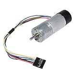 Encoder Metal Gearmotor 12V DC High Speed 300RPM Gear Motor with Encoder for Arduino and 3D Printers
Not sure if the gear ratio is right, but the encoder keeps the option to interface with an arduino build open & 12v power is convenient. Still kicking around mount & whip options, have something sketched out for testing. |
|
|
|
|
[#42]
Been having some minor issues with my SB-200 I had an output Band switch burn up a long time ago due to open coax on 10m. I mostly use this amp on 40 meter but I noticed I was at full engagement on 80m on the Load capacitor but the best I could get for output was about 350 watts and about 450-500 on 40m. I have also planned on converting this amp over to 240v. Decided today to start the tear down. I can tell you the output band switch on these are a PITA. So I got the switch out and replaced. Did a test run on 120v and found I get about 600w out now on 80m and about 550w out on 40-15 and about 400 on 10 now. That is with about 75 watts of drive. I realized why when I took the band switch apart there was some damage on the band switch that is hard to see. I also had an RX issue with the relay and I documented that below.
 Dirty HF Amp relay causing issues with Icom RX. I also cleaned the relays with Deoxit, and changed the soft start resistors from 10ohm to 20ohm and moved the jumper to 240v, and rewired the plug. Then I had an issue of intermittent filaments on the tubes but the panel lamp would stay running. I ended up tracing that down to loose tube socket. Tightened up the pins and all is good now. Currently looking for a SB-220 or an LDMOS SS amp, but I will keep running this one for now. Super happy how it turned out. Now it is time to build the control box for my 1KW Harris amp on 6m and the second one I have coming for 2m band. |
|
|
|
CO, USA
|
[#43]
Antenna had flop-osis after a windstorm. "Mule, plz halp!"
 Been ~5mos since i've been on a tower. Went through all my gear, thorough inspection, pack it up into gearbag(s) and toss it in the pickup.  Snap on a post level, add a new pair of brackets, pull the antenna level again. Put a wrench on every bolt, make sure everything's tight. Gets my seal of approval.  Radio to the gang down there "Everything look good? TTA and RX OK? I'm cleaned up and ready to descend." "Everything looks good down here."  Antenna looks even better in the rearview. 
|
|
|
|
[#44]
Originally Posted By stanprophet09: Been having some minor issues with my SB-200 I had an output Band switch burn up a long time ago due to open coax on 10m. I mostly use this amp on 40 meter but I noticed I was at full engagement on 80m on the Load capacitor but the best I could get for output was about 350 watts and about 450-500 on 40m. I have also planned on converting this amp over to 240v. Decided today to start the tear down. I can tell you the output band switch on these are a PITA. So I got the switch out and replaced. Did a test run on 120v and found I get about 600w out now on 80m and about 550w out on 40-15 and about 400 on 10 now. That is with about 75 watts of drive. I realized why when I took the band switch apart there was some damage on the band switch that is hard to see. I also had an RX issue with the relay and I documented that below. https://www.ar15.com/media/mediaFiles/199367/IMG_9749_JPG-3193414.JPG https://www.ar15.com/media/mediaFiles/199367/IMG_9750_jpg-3193415.JPG https://www.ar15.com/media/mediaFiles/199367/IMG_9754_JPG-3193416.JPG https://www.ar15.com/media/mediaFiles/199367/IMG_9755__1__JPG-3193417.JPG https://www.ar15.com/media/mediaFiles/199367/IMG_9756__1__JPG-3193418.JPG I also cleaned the relays with Deoxit, and changed the soft start resistors from 10ohm to 20ohm and moved the jumper to 240v, and rewired the plug. Then I had an issue of intermittent filaments on the tubes but the panel lamp would stay running. I ended up tracing that down to loose tube socket. Tightened up the pins and all is good now. Currently looking for a SB-220 or an LDMOS SS amp, but I will keep running this one for now. Super happy how it turned out. Now it is time to build the control box for my 1KW Harris amp on 6m and the second one I have coming for 2m band. My SB220 band switch wafers were solid black. I used some deoxit spray and I hope it works. I did the best I could with a Q-Tip and then just gave up and sprayed it down and soaked it. I've read that the spray can be bad for the ceramic wafers, but given the condition they were in, I decided that aggressive cleaning would be more beneficial than harmful. After the spray and cycling the switch back and first, a bright silver line appeared on the rotor contact. I am going to hope for the best. |
|
|
|
|
[Last Edit: Jambalaya]
[#45]
Originally Posted By SnowMule: Antenna had flop-osis after a windstorm. "Mule, plz halp!" https://photos.smugmug.com/photos/i-f8gppBn/0/XL/i-f8gppBn-XL.jpg Been ~5mos since i've been on a tower. Went through all my gear, thorough inspection, pack it up into gearbag(s) and toss it in the pickup. https://photos.smugmug.com/photos/i-GMghdxf/0/XL/i-GMghdxf-XL.jpg Snap on a post level, add a new pair of brackets, pull the antenna level again. Put a wrench on every bolt, make sure everything's tight. Gets my seal of approval. https://photos.smugmug.com/photos/i-MWZjTTd/0/XL/i-MWZjTTd-XL.jpg Radio to the gang down there "Everything look good? TTA and RX OK? I'm cleaned up and ready to descend." "Everything looks good down here." https://photos.smugmug.com/photos/i-hHvSTkd/0/XL/i-hHvSTkd-XL.jpg Antenna looks even better in the rearview. https://photos.smugmug.com/photos/i-MdCLR9j/0/XL/i-MdCLR9j-XL.jpg I think you win the prize for "job with a view". I always enjoy reading your posts. |
|
|
|
CO, USA
|
[#46]
Originally Posted By Jambalaya: I think you win the prize for "job with a view". I always enjoy reading your posts.  Got a couple positions open, need an in-building amplifier/DAS installer or two (entry-level), and one of the agencies I work with is lookin for some engineering-level experienced radio techs (Motorola and Kenwood systems). 
|
|
|
|
[#47]
^ Yea I always think 'What a cool job' until the look-down picture.
Then it's 'Fuuuuuuu..... That!' |
|
|
|
|
[Last Edit: whollyshite]
[#48]
Rookie project compared to most on here.
I started my first box project. I'm still trying to figure out G90 and 20Ah battery in the box now. I've only turned the radio on once... I have a mobile wireless router, RPi, and a ssd that I want to mount on the lid. I'm still waiting on a powerpole distribution block, an rtl-sdr, 2 buck converters to use the battery to add power via usb-c, all on order. I'm looking to find some of the lilygo t-echos, but I have a few t-beams for now. I need to get my 3D printer back up and running to print up some cases. I'm hoping most of the stuff will mount on the bottom of the lid. ETA: Damn cats... Trigger warning for cat hair. |
|
|
|
|
[#49]
Started on my amp remote control head today. I was originally going to use this for my Harris 6m amp, but with the 2M on the way I have decided that I will dedicate this as my VHF and above. But I will be using this to monitor the 50V power supply. I will run the amp Bird line sections into the back of this with a band switch so I can monitor power. So overall it will be a 14v 100 amp power supply with Voltage reading for the 14V and 50V. It has a 4 event sequencer in it, a Bird PEP kit with a 2X/5X switch. I will have the 240v on the main power switch with the LED and a switch for the Amp Contactors. I will also have a standby switch for all of the amps. The Watt meter has a switch for the LED backlight. Right now I have it wired for the PEP kit with the 9v battery and will be using a DC to DC buck converter to power the peak kit. Still need to machine the back cover for the 240v plug and the 75 amp power pole and matching a piece that can hold it to the box. I put a bunch of RCA connectors for the Sequencer. I also put 6 BNC connector on the back for the bird line sections to come into the band switch so I will be using this on the 6m amp for power monitoring until I get my other one built.
The power pole housing would like the panel to be thicker so I potted it with some E6000 and will machine a spacer for it later. Still need to finish the wiring of it and get some stubby switches as the local supply only had one and I like them better than the long ones. I did not hook the band switch up since I am getting ready to jump on a 6m net so wanted to test out the meter, wire is long enough to cut and still make it to the band switch when I finish up the wiring. Have the HP power supply mounted with 3m mounting tape right now but will be adding brackets that I am 3d printing. All of the board standoffs and insulators were machined out of Delrin on my lathe and the peak kit ones isolate the bolts from the cabinet and are held down through the meter stud holes. My meter has a non standard mounting tab so had to adapt the kit to fit this box. Plan is to build another one like this for the Harris 6M amp and the HF/6M 2kw LDMOS kit I will be building this year. I may not put the sequencer in it, since I have one in a project enclosure and there is no need for a power supply in the other one. |
|
|
|
|
[#50]
Moved the 160m FWL feedline back over to the wall penetration. No need for the former offset since some interfering trees are now gone. Adjusted the length & set up a counterweight by the wall.
Open wire to the FWL feedpoint. The top horizontal wire is the loop. The lower one is the inverted "L" for 160m coming off a coax 40m trap at the Hustler BTV. |
|
|
|
 Win a FREE Membership!
Sign up for the ARFCOM weekly newsletter and be entered to win a free ARFCOM membership. One new winner* is announced every week!
You will receive an email every Friday morning featuring the latest chatter from the hottest topics, breaking news surrounding legislation, as well as exclusive deals only available to ARFCOM email subscribers.

AR15.COM is the world's largest firearm community and is a gathering place for firearm enthusiasts of all types.
From hunters and military members, to competition shooters and general firearm enthusiasts, we welcome anyone who values and respects the way of the firearm.

Subscribe to our monthly Newsletter to receive firearm news, product discounts from your favorite Industry Partners, and more.
Copyright © 1996-2024 AR15.COM LLC. All Rights Reserved.
Any use of this content without express written consent is prohibited.
AR15.Com reserves the right to overwrite or replace any affiliate, commercial, or monetizable links, posted by users, with our own.