|
[#1]
Most auto voltage regulators control the alternator's field lead to regulate the output voltage. Not really what you are looking for. How much current do you need?
RS |
|
|
|
[#2]
I suppose you could make it work some way but I honestly have no idea off of the top of my head if it's plug and play. How much current are we talking about? Just make a voltage divider out of something if the current isn't too high.
|
|
|
|
[#3]
As asked, current draw? Maybe a light bulb in series?
|
|
|
|
[#4]
What is the 16v source, and what is it powering?
|
|
|
|
[#5]
String a few diodes together and utilize their 0.7v drop per diode. Should be a few in that alternator.
|
|
|
|
[#6]
Quoted:
String a few diodes together and utilize their 0.7v drop per diode. Should be a few in that alternator. This would be my vote as well, assuming he doesn't have a Zener diode laying around If he has a couple high-wattage resistors and the load is low, he could also do a voltage divider, but the power dissipation will be huge. |
|
|
|
[#7]
|
|
|
|
[#8]
Quoted:
I need to convert 16v dc to ~13.8v dc. The kicker is I am about 2 hours away from a radio shack, and won't be here long enough to order something. What I am wondering is if a car voltage regulator (like 70s model Ford) will work for what I need. in it's current form, there is important information missing from this post. ar-jedi |
|
|
|
[#9]
Voltage regulators control input/output current to the alternator field circuit.
you could modify your circuit to PWM 16v to your required voltage |
|
|
|
[#10]
Sorry. It is for my kxpa100 amplifier so max 20 amps.
|
|
|
|
[#11]
For that kind if power Iwould suggest you get a dc-dc ppower supply.
What is your 16v source? |
|
|
|
[#12]
I'm using BB-2590s
http://www.bren-tronics.com/bt-70791a.html I might be heading to town soon. Should I go with a voltage regulator or zener diodes? |
|
|
|
[#13]
Quoted:
I'm using BB-2590s http://www.bren-tronics.com/bt-70791a.html I might be heading to town soon. Should I go with a voltage regulator or zener diodes? voltage regulator. zener diodes usually only handle milliamps of current. also i think you mentioned running an amp off it? 20 amps current draw? gonna need a beefy regulator and heat sink. 20a * (16v - 12v) = 80w of dissipated heat for a linear regulator. The ones form radio shack are rated 1.5a each and need a certain amount of cooling from emitting smoke. |
|
|
|
[#14]
I think you're well beyond anything using a zener diode.
|
|
|
|
[#15]
Quoted:
I'm using BB-2590s http://www.bren-tronics.com/bt-70791a.html I might be heading to town soon. Should I go with a voltage regulator or zener diodes? Quoted:
I'm using BB-2590s http://www.bren-tronics.com/bt-70791a.html I might be heading to town soon. Should I go with a voltage regulator or zener diodes? if you get diodes, get a heatsink to go with them. radio spec: Specifications KXPA100 Amplifier Supply Voltage and Current 12-15 Vdc (13.8 V nominal), at least 24 A peak capacity. battery spec: BT-70791A (BB-2590/U) Rechargeable, Lithium-Ion Battery Voltage 28.8V, Two (2) Sections each 14.4 Maximum Voltage 33.0V, Two (2) Sections each 16.5 V so you need to drop 1.5Vdc at up to 24A. this a healthy amount of power at peak draw (1.5Vdc * ~20A) = 30W. fortunately, unless you are running FM, that peak should not be frequently seen. i would obtain a 25A bridge rectifier and then get some heatsinking on it. use 2 of the 4 diodes. most 4 tab bridge packages will have a mounting hole, which makes attaching a heatsink straightforward.. eta don't forget that any solution here is going to cut into your apparent battery capacity. regulators and diodes and DC/DC converters all have inefficiencies. some more, some less. but Pin != Pout, ever. ar-jedi 
|
|
|
|
[#16]
Quoted:
if you get diodes, get a heatsink to go with them. radio spec: battery spec: so you need to drop 1.5Vdc at up to 24A. this a healthy amount of power at peak draw (1.5Vdc * ~20A) = 30W. fortunately, unless you are running FM, that peak should not be frequently seen. i would obtain a 25A bridge rectifier and then get some heatsinking on it. use 2 of the 4 diodes. most 4 tab bridge packages will have a mounting hole, which makes attaching a heatsink straightforward.. eta don't forget that any solution here is going to cut into your apparent battery capacity. regulators and diodes and DC/DC converters all have inefficiencies. some more, some less. but Pin != Pout, ever. ar-jedi http://www.pirate4x4.com/forum/attachments/electrical-wiring/1064441d1381284230-what-diode-bridge-rectifier.jpg Quoted:
Quoted:
I'm using BB-2590s http://www.bren-tronics.com/bt-70791a.html I might be heading to town soon. Should I go with a voltage regulator or zener diodes? if you get diodes, get a heatsink to go with them. radio spec: Specifications KXPA100 Amplifier Supply Voltage and Current 12-15 Vdc (13.8 V nominal), at least 24 A peak capacity. battery spec: BT-70791A (BB-2590/U) Rechargeable, Lithium-Ion Battery Voltage 28.8V, Two (2) Sections each 14.4 Maximum Voltage 33.0V, Two (2) Sections each 16.5 V so you need to drop 1.5Vdc at up to 24A. this a healthy amount of power at peak draw (1.5Vdc * ~20A) = 30W. fortunately, unless you are running FM, that peak should not be frequently seen. i would obtain a 25A bridge rectifier and then get some heatsinking on it. use 2 of the 4 diodes. most 4 tab bridge packages will have a mounting hole, which makes attaching a heatsink straightforward.. eta don't forget that any solution here is going to cut into your apparent battery capacity. regulators and diodes and DC/DC converters all have inefficiencies. some more, some less. but Pin != Pout, ever. ar-jedi http://www.pirate4x4.com/forum/attachments/electrical-wiring/1064441d1381284230-what-diode-bridge-rectifier.jpg oh yea radio shack will have one of those that should work with a heatsink too. |
|
|
|
[#17]
The problem with using diode voltage drops is that once the battery voltage drops, so will your output power.
One way around this would be to use a DC/DC switching power supply but they generally need a higher input voltage for 13.8 out...something like 18V-30V You may get around the problem, assuming you have not yet acquired the lithium cells, by using 2 cells with half the volume/Ah in series and then drop the voltage with a switcher. Good Luck M. |
|
|
|
[#18]
Quoted:
The problem with using diode voltage drops is that once the battery voltage drops, so will your output power. One way around this would be to use a DC/DC switching power supply but they generally need a higher input voltage for 13.8 out...something like 18V-30V it's trading one problem for another; DC/DC's have inherent switching noise (conducted and radiated), and furthermore you need to look at the dynamic response specs. going from 1A RX to 20A TX is no issue with a couple of diodes in series; a DC/DC converter is a little more complicated and some study of the datasheet is needed. ar-jedi |
|
|
|
[#19]
So I found this guy. $4 is well within the budget and I hope there might be one in stock.
What is the best way to wire it up? Back home I have a little heat sink that would work perfect, but for now I might just have to use a chunk of aluminum. How much power is wasted in this application? Is it dissipating heat without a current draw? |
|
|
|
[#20]
those nitwits can't even bother to post a datasheet with the item. Quoted:
What is the best way to wire it up? 10AWG wire with crimped on FASTON tabs. Quoted:
Back home I have a little heat sink that would work perfect, but for now I might just have to use a chunk of aluminum. screw it to any decent size chunk of aluminum. the most important adder is some thermal coupling grease, which fills in the "gaps" between the two parts and decreases thermal resistance from the semiconductor package to the heatsink. RS should also have some thermal coupling grease on the shelf as well; a couple of bucks for a toothpaste travel size tube. Quoted:
How much power is wasted in this application? Is it dissipating heat without a current draw? the power lost in the diode is equal to the current (Ifwd) x the voltage drop (Vfwd) across the diode. Ifwd will range from 0 to 20A, given your amplifier. Vfwd will range from about 0.75Vdc (per diode) at low loads (1-2A), rising to about 1.00Vdc (per diode) at high loads (15-25A). as you can see... about 1.5W will be dissipated at the diodes during RX. (1A x 0.75V/diode x 2 diodes) about 40W will be dissipated at the diodes during TX at peak current draw. (20A x 1V/diode x 2 diodes). i'm guessing your average current during TX will be about 40% of peak; this is 8A or so. let's call it 10A just to make sure. about 18W will be dissipated at the diodes during TX at average current draw. (10A x 0.9V/diode x 2 diodes). you need a heatsink. ar-jedi 
|
|
|
|
[#21]
Thanks Jedi.
So if I am thinking correctly, the grounds should be common then run my battery to 2 of the tabs and then the other 2 tabs to my distribution block/amp? I don't have the stuff to do it here but when I get home would it be possible to build a little circuit that if voltage is <15v it switches the diode out? |
|
|
|
[#22]
I'm probably late...
The concern is the 16V number (some say it's really 16.5, but I would call elecraft). Go with 100 ft of 10AWG power cable. Drops under 16V at .25a load (estimate 15.95) and drops down to like 12.8 under 16A (which is my "full power" average figure. Your'e not doing 100 Watt key down are you? Do you have an inverter with you to run off the car and a PSU? |
|
|
|
[#23]
Quoted:
I'm probably late... The concern is the 16V number (some say it's really 16.5, but I would call elecraft). Go with 100 ft of 10AWG power cable. Drops under 16V at .25a load (estimate 15.95) and drops down to like 12.8 under 16A (which is my "full power" average figure. Your'e not doing 100 Watt key down are you? Do you have an inverter with you to run off the car and a PSU? Yes I would plan on rarely doing 100w key down. The only problem with the 100' of wire is the bulk. Have been using a mix of my A123 battery and a spare car battery. |
|
|
|
[#24]
Jedi,
I got a BR from Rat Shack and got it hooked up. I am only getting a drop from 16.4 to 15.9 |
|
|
|
[#25]
Quoted:
Jedi, I got a BR from Rat Shack and got it hooked up. I am only getting a drop from 16.4 to 15.9 HI GCW, How many diodes do you have hooked up in series? Is the rig in TX or receive with this reading? 73, Rob |
|
|
|
[#26]
I think it is 2 diodes. Of the four pins the two opposite of each other go to dc in and the notched corner and the one.opposite of it.go to dc out.
Right now I.am just checking with a multi meter with no load. Elecraft says max in is 15v so I was trying to get.that while the.batteries were unloaded. |
|
|
|
[#27]
Sorry-thought this was a one off solution until you can engineer the right solution

|
|
|
|
[#28]
Quoted:
I think it is 2 diodes. Of the four pins the two opposite of each other go to dc in and the notched corner and the one.opposite of it.go to dc out. Right now I.am just checking with a multi meter with no load. Elecraft says max in is 15v so I was trying to get.that while the.batteries were unloaded. If you can figure out the current draw of the KX3, make up a resistor based on the voltage measured that duplicates the KX3, then measure the drop across the diodes and the "output" voltage. I'd be curious. 73, Rob |
|
|
|
[#29]
I just bought 2 more BR from radio shack. We will see where it goes in a couple hours.
|
|
|
|
[#30]
Email Elecraft, they should give you the best suggestion. Since the KXPA100 is designed for automobile applications (it is right? I dont know), I'd be surprised if it couldn't just take 16V...
|
|
|
|
[#31]
GCW, I think you connected the Bridge rectifier incorrectly.
I'm not 100% certain of your current connections, but I think this is how you need it. Quick & dirty, please excuse my MSPaint:  |
|
|
|
[#32]
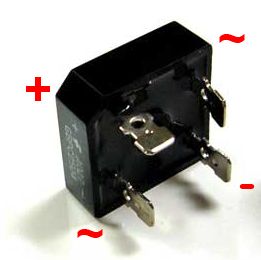
Use this picture to help wire the rectifier based on my previous schematic.
 |
|
|
|
[#33]
I can't edit from my phone for some reason...
But: Please disregard my diagram as I brain-farted and that would only drop you about .7 volts. You should ignore the AC terminals and connect battery to "-" rectifier terminal and radio to "+" rectifier terminal.
|
|
|
|
[#34]
In the drawing above, the battery + would go left terminal, the radio + to the right terminal, and the top and bottom would be unused.
Crudely edited for blwngazkit. 
|
|
|
|
[#35]
Quoted: In the drawing above, the battery + would go left terminal, the radio + to the right terminal, and the top and bottom would be unused. Crudely edited for blwngazkit. http://i.imgur.com/3Uyq72b.png Thanks
|
|
|
|
[#36]
Ok I just wired it like described above. With 1 I could only get .4v drop. I put 3 in series and only got to 15.28v
|
|
|
|
[#37]
at what current draw did you make those measurements? ar-jedi |
|
|
|
[#38]
The forward voltage drop of some rectifiers is much lower than 0.7V by design, which looks to be the case with that one. - ETA: Not likely with this particular device after reading more...
You could keep adding more of those in series, or go to discreet diodes with a known voltage drop. |
|
|
|
[#39]
Quoted:
at what current draw did you make those measurements? ar-jedi Just my multi meter... |
|
|
|
[#40]
RE: What ar-jedi was asking about:
From a Fairchild unit that's probably the same or similar. 
|
|
|
|
[#41]
Ok so I have a 12v-120v AC inverter that draws about .4A on standby. That is about the same as the KXPA100.
With the load it is 14.7V |
|
|
|
[#42]
Either something's wrong or RadioShack changed suppliers.
I've got one of those 25a 50v full wave rectifiers from a year or two ago and just checked it; mine drops ~1.4V on my project board powering an indicator lamp.
|
|
|
|
[#43]


|
|
|
|
[#44]
On the air with "down and dirty"! You are on the air, aren't you? |
|
|
|
[#45]
I have lightning within 5 miles
|
|
|
|
[#46]
Quoted:
I have lightning within 5 miles Don't worry, your batteries will protect your radio from lightning strikes.
|
|
|
|
[#47]
Quoted:
RE: What ar-jedi was asking about: From a Fairchild unit that's probably the same or similar. http://i.imgur.com/OMhg3Mh.jpg ^^^ this. in any diode the forward voltage drop is a function of forward current. in the "ideal" diode concept there is not, but in practical application of a semiconductor diode there will be a similar curve as shown. note that there are devices called "ideal diodes" which are made up of a FET and a sensing/control circuit. the idea results in a "diode" without forward voltage drop, and without the non-linear forward voltage vs forward current curve. the only drop is the minimal Rds (drain-to-source resistance) across the FET; this resistance is typically in the 10->100 milliohm range. ar-jedi eta see, for example, http://www.linear.com/solutions/1465 
|
|
|
|
[#48]
Quoted:
Don't worry, your batteries will protect your radio from lightning strikes. Quoted:
Quoted:
I have lightning within 5 miles Don't worry, your batteries will protect your radio from lightning strikes. it will be a few years before this is forgotten! lol. ar-jedi |
|
|
|
[#49]
Quoted:
Don't worry, your batteries will protect your radio from lightning strikes. Quoted:
Quoted:
I have lightning within 5 miles Don't worry, your batteries will protect your radio from lightning strikes. Curse you Brun!!! That there is my horse to beat! Can't blame you though...with it all tee'd up for you like that. |
|
|
|
[#50]
Thanks to all that helped! I used it today trying to QSO on 20m. Not a problem at all and the gas gauges didn't move at all. When I get back home I am going to see how much use I can really get out of them.

Now I need to repackage it and redo the heat sink. I think I am going to add a bypass switch and one of the small cheap volt meter I have seen in the emcomm threads. That way when/if the voltage gets low enough I can kick the rectifier out of the circuit. |
|
|
 Win a FREE Membership!
Sign up for the ARFCOM weekly newsletter and be entered to win a free ARFCOM membership. One new winner* is announced every week!
You will receive an email every Friday morning featuring the latest chatter from the hottest topics, breaking news surrounding legislation, as well as exclusive deals only available to ARFCOM email subscribers.

AR15.COM is the world's largest firearm community and is a gathering place for firearm enthusiasts of all types.
From hunters and military members, to competition shooters and general firearm enthusiasts, we welcome anyone who values and respects the way of the firearm.

Subscribe to our monthly Newsletter to receive firearm news, product discounts from your favorite Industry Partners, and more.
Copyright © 1996-2024 AR15.COM LLC. All Rights Reserved.
Any use of this content without express written consent is prohibited.
AR15.Com reserves the right to overwrite or replace any affiliate, commercial, or monetizable links, posted by users, with our own.