|
Posted: 5/30/2014 1:28:06 AM EDT
I posted this in another thread, but am making a separate post here.
We all want to make an antenna that will use a minimum of wire / occupied space, yet work as many bands as possible. One way is to make a simple dipole, or rather, a number of dipoles, one for each band. But if we do this, we are now complicating things, lots of coax, antenna switches, lots of wire, the back yard will look like a spider web. We can put multiple dipoles in parallel, feed them with one piece of coax, no switches, switching will be automatic! This is known as a "fan dipole". Still, there is a lot of wire hung about. A 40 m center fed dipole will work 15 meters with a tuner. It will be slightly off from being exactly 3 x the fundamental frequency due to end effects, but will be close enough that a tuner will let it work both bands. A 40 m center fed dipole will not work 20 m or 10 m. OK, 40 and 15 m from one dipole... doing a little better, but not good enough. We want more bands!!! 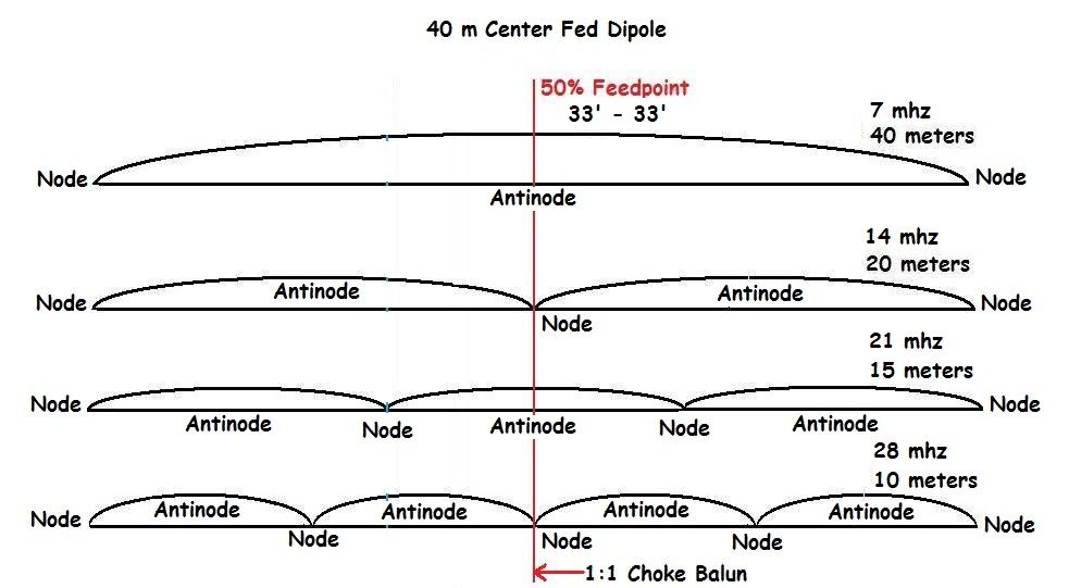
An 80 m center fed dipole will work 30 m and 17 m, and 12 m with a little assist from a tuner (odd numbered harmonics). I said 80 m, not 75. It must be tuned low in the 80 m band, down around 3.500 to 3.550 mhz so that the harmonics will coincide with the nearest ham band. 3.5 mhz x 1 = 3.5 mhz. 3.5 mhz x 3 = 10.5 mhz - close enough to tune the 30 m band. 3.5 mhz x 5 = 17.5 mhz - close enough to tune the 17 m band. etc. 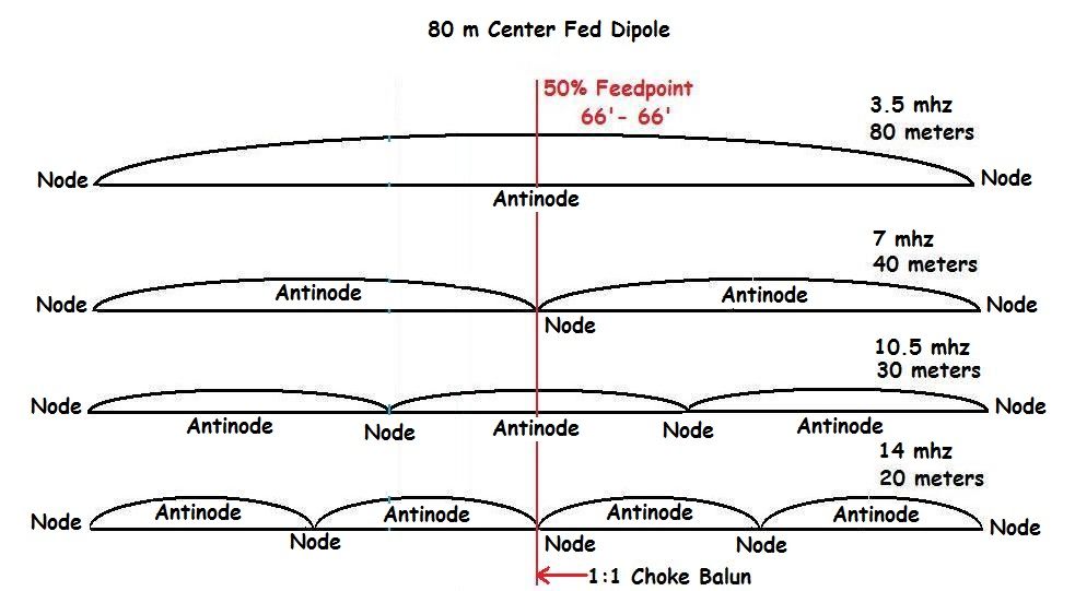
Center fed dipoles will only work the odd numbered harmonics. But if we make a fan dipole with 80 m and 40 m segments, we then have 80, 30, 17 m (and 12 m) and 40 and 15 m. That gives us 6 ham bands with two dipoles in parallel. Then we can fill in with a third pair for the all important 20 meter band. Now we have 80, 40, 30, 20, 17, 15, 12 meters from just three pairs of elements in our fan dipole! Not bad at all! Still, that's a lot of wire in the back yard. (Helpful hint... you still need a tuner to work 75 meters, and get the other bands just right.) For the same overall length of wire, an offset center fed dipole, aka OCFD or "Windom" (sic), will work both even and odd numbered harmonics... but which ones depends on the "split", that is, just where along the span of wire the feedpoint is located. 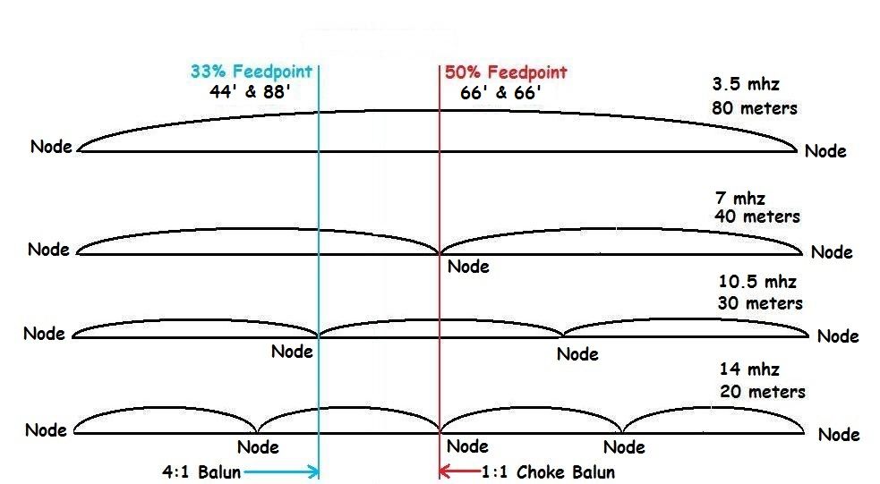
At the antinode, the center of the 80 m dipole, the impedance is approximately 50 ohms. The impedance at the ends, where no current can flow, approaches infinity. Would you not agree that somewhere between the center and either end we might find a point that is about 200 ohms? That point would be about 1/3 of the way from either end, and if we use a 4:1 current balun at that point we will present 50 ohms back to the transmitter. I present to you, The OFFSET CENTER Fed Dipole! A 40 meter OCFD is 66' overall length, same as a 40 m center fed dipole. But the split would be something like 22' + 44' (33% feedpoint), or 25' + 41' (38%). This OCFD will work 40, 20, and 10 m bands. The 33% or 1/3 - 2/3 split will have great difficulty, very high impedance on the 15 m band. This is because for that frequency, 21 mhz, the 66' length is working as three half-wavelengths. There are three antinodes distributed along the 66' of wire. An antinode is a point where there is maximum current and minimum voltage, and minimum impedance (Ohm's law). 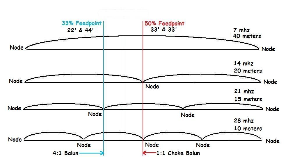
But there are also four nodes... points where there is minimum current and maximum voltage, and thus near infinite impedance. Those points are at each end, and one at 22' and another at 44' along the wire. You can't drive the antenna at those points, and for the same reason that you can't drive a 40 m center fed dipole to work the 20 m band... there is a node directly in the middle where the feedpoint is located. So, a little problem... the 66' overall length 40 m OCFD with 1/3 - 2/3 split (33%) will not work the 15 m band, nor will the 80 m version work 30 m and 15 m. The feedpoint is directly on a node for those bands. But by moving the feedpoint over one way or the other off that 1/3 node we can again drive those 3 x harmonics. This will change the impedance for other bands, and a band may be "lost" or maybe just higher impedance. YOU STILL NEED A TUNER. Other splits to try, for the 80 m OCFD, try 38' + 94' (29% feedpoint) or 50' + 82' (38% feedpoint). For the 40 m OCFD, try the 25' + 41' (38% feedpoint). |
|
|
|
[#1]
Thanks Jupiter7200--good write-up of a great antenna.
I run an overall length 135' antenna ; one leg is 45' the other leg is 90'. This has given me 6, 10, 12, 17, 20, 40 and 80 meters. All of which tune using the built in tuner on the Yaesu FT-950. May not be maximized, but I have worked most of the world with it, just 20-25' off the ground! Of course, I am just a few blocks from the ocean, so I suspect I get some help from a salt water ground plane. |
|
|
|
[#2]
Nice write up! I sure made a ton of QSO's with my 33% split OCF version. Even though its more wire & work, I like my fan dipole better. With four 1/2 wave wire elements (10, 20, 40, 80), I can also work 12, 15, 17, & 30 with the aid of a tuner. I can't imagine not having those bands now.
My wire elements are spread out instead of running parallel to each other. My freaky fan dipole |
|
|
|
[#3]
We (club) use a 66' overall length OCFD sometimes for special events. In the past it used the 22' & 44' (1/3 - 2/3 or 33%) split, but last year I trimmed the 44' segment back to 41' and replaced the 22' piece with 25'. I did not simply splice on a few more feet the splice, soldered or not, will always be a weak spot. The 22' can be used to make a 15 m dipole.
Our club also has, among its several HF antennas, an OCFD with 29% split, 39' & 93'. This one is still high on 15 meters, but not as bad as a 1/3 - 2/3 split. It has low SWR on 40, 20, and 17 meters, being between 1.4 and 1.6:1 SWR. 12 and 10 meters are around 1.7:1. 80 meters is a little high, 2.5 or so, and up in the 75 m range it is 3-4:1 SWR. But at that frequency coax loss is not bad at all and a tuner easily corrects that problem. So, you still need a tuner, but only two wires and coax... not bad for a low visibility antenna. ~ Jup |
|
|
|
[#4]
Quoted:
... not bad for a low visibility antenna. ~ Jup That's a good point. I had to tell & point out to people, (non hams) where my dipole was. Half could only see the feed line. Black cord is hard to see, especially is there is a background to break it up. |
|
|
|
[#5]
While an OCFD is no more or less efficient than a centerfed dipole, the main advantage of the OCFD is working more bands.
Our club station's antenna system include a 75 m dipole tuned about 3.900 mhz, middle of the General phone portion of the 80/75 m band, hung about 40' up a 60' Rohn tower, a Mosley 10-15-20 m Tribander, and a 132' overall length (80 m on up) OCFD hung about 35' up. The OCFD is the only antenna capable of 40 meters. For this Field Day we worked 2F, just two transmitters working as an EOC. We ran only 100 w SSB, and got reports on 40 m of 5-9's, 5-9+20, etc, and "You're the strongest signal on the band" from over 1000 miles away. I don't know about that, but we could make all the contacts we wanted just about as fast as we could work them. It is as effective as a single band dipole and should be seriously considered. Final notes: The best balun recommendation, according to many on the Windom Yahoo Group, is the #4115 4:1 dual core by Balun Designs. There are several configurations, with and without eyebolts, etc, so you can choose the one best suited to your needs. I chose the #4115et, which has eyebolts on top and sides. http://www.balundesigns.com/servlet/the-78/4-cln-1-dual-core-current/Detail From my experiments cutting wire, for the most even SWR from band to band, cut the wire to 44' & 22' for 40 m on up, or 88' and 44' for 80 m on up. This is for 14 ga insulated stranded wire. This "split" will not work 15 meters. A little more variation in band to band SWR, but still easily tuned, and will work 15 meters, 41' & 25' for 40 m on up, or 82' & 50' for 80 m on up. This is for 14 ga insulated stranded wire. Yes, you still need a tuner, but the tuner will not be working too hard to get a good SWR at the radio end of the coax, and coax losses will not be excessive nor audible. |
|
|
|
[#6]
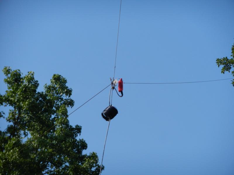
By coincidence, I just put up an OCF at the house yesterday. I was using AI4JI's description as a guide & used a 14% feedpoint offset, giving legs of 46' 9.5" and 83' 2.5" using 14 AWG stranded THHN.
I had just made a new run of LMR400 equivilant for the 2m/70cm, so the original RG-8x, complete with ugly balun wraps, was available for re-use. For the time being, I am using a homebrew 4:1 current balun made on a type 43 ferrite core. I set up a jig on the deck rail using three screws, with sections of drinking straw to protect the wire sheath, placed at origin, 15' and 25' to make it easier to measure wire while working alone. 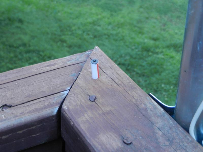
Using a foot of rebar as a weight, I threw paracord over a couple of tree limbs to define a line paralleling the back deck. The height was constrained by what was reachable from the lawn border (& my tossing ability). A couple of ceramic fence wire insulators were used at the connection points. 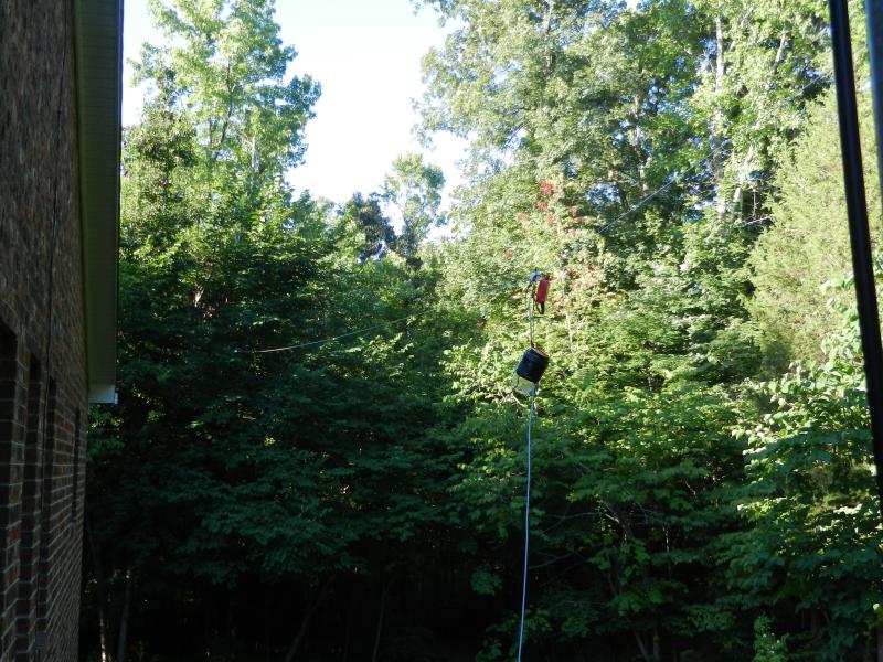
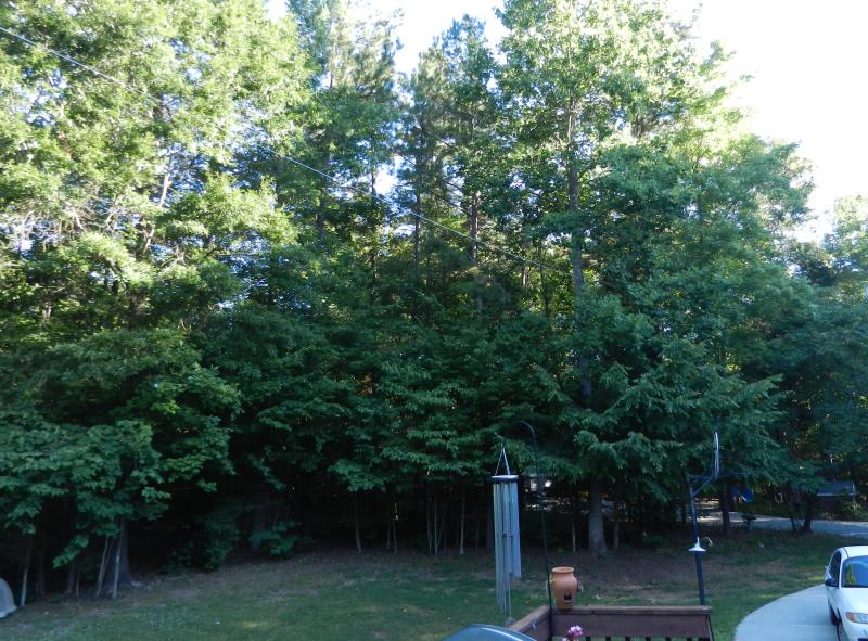
So far, the most impact has been on access to 80m. I could tune for it on the MFJ1796 (although it only claims 2, 6, 10, 15, 20 & 40 meters) using the MFJ941D tuner on the FT-707, but the wire brings it in at a much higher level (what is coming in as a normal audio using the 1796, becomes painfully loud when switched over to coming in from the wire). In other segments they seem roughly equivalent with 1796 having the edge for signal-noise in some cases. Perhaps due to the almost perfect north-south orientation of the wire, hitting New Hampshire on 40 meters from here in NC seemed to be easier on the vertically oriented 1796 than with the wire. Nick |
|
|
|
[#7]
Good comments!
I know a guy with five separate antennas that cover the same bands, and sometimes one will be better, or less noisy, sometimes another. But he has enough antennas to make a choice. |
|
|
|
[#8]
Quoted:
Good comments! I know a guy with five separate antennas that cover the same bands, and sometimes one will be better, or less noisy, sometimes another. But he has enough antennas to make a choice. That's a problem I want to have. 
|
|
|
|
[#9]
Thank you for this write up, I was going to buy a Buckmaster OCFD, but with the help of your this thread I might attempt to build my own and save a couple of bucks.
|
|
|
|
[#10]
Quoted:
Thank you for this write up, I was going to buy a Buckmaster OCFD, but with the help of your this thread I might attempt to build my own and save a couple of bucks. Yes, you can do as well or better. Buy the Balun Designs balun, or at least, a good quality 4:1 current balun. 14 ga stranded insulated MTW wire. Don't worry about trying to tune it exactly to a frequency... it covers lots of bands, and you can't tune it for all. That's what tuners are for. Don't buy into the hype "work 13 bands, no tuner required." I'm telling you, you need a tuner. An 80 m OCFD should resonate at the bottom of the 80 m band, in the 3.500 - 3.550 mhz range. Do not try to tune it to the 3.8-4.0 General Phone portion (75 m) as that will throw resonance of all of the higher bands up above the bands. 3.55 - 7.1 - 14.2 mhz, etc... is better than 3.9 - 7.8 - 15.6 mhz, etc. Just cut the wire to the lengths I specified earlier. |
|
|
|
[#11]
Quoted:
By coincidence, I just put up an OCF at the house yesterday. I was using AI4JI's description as a guide & used a 14% feedpoint offset, giving legs of 46' 9.5" and 83' 2.5" using 14 AWG stranded THHN. I had just made a new run of LMR400 equivilant for the 2m/70cm, so the original RG-8x, complete with ugly balun wraps, was available for re-use. For the time being, I am using a homebrew 4:1 current balun made on a type 43 ferrite core. I set up a jig on the deck rail using three screws, with sections of drinking straw to protect the wire sheath, placed at origin, 15' and 25' to make it easier to measure wire while working alone. http://www.skhowell.com/images/OCF-dipole-4.jpg Using a foot of rebar as a weight, I threw paracord over a couple of tree limbs to define a line paralleling the back deck. The height was constrained by what was reachable from the lawn border (& my tossing ability). A couple of ceramic fence wire insulators were used at the connection points. http://www.skhowell.com/images/OCF-dipole-2.jpg http://www.skhowell.com/images/OCF-dipole-3.jpg So far, the most impact has been on access to 80m. I could tune for it on the MFJ1796 (although it only claims 2, 6, 10, 15, 20 & 40 meters) using the MFJ941D tuner on the FT-707, but the wire brings it in at a much higher level (what is coming in as a normal audio using the 1796, becomes painfully loud when switched over to coming in from the wire). In other segments they seem roughly equivalent with 1796 having the edge for signal-noise in some cases. Perhaps due to the almost perfect north-south orientation of the wire, hitting New Hampshire on 40 meters from here in NC seemed to be easier on the vertically oriented 1796 than with the wire. Nick How high is that? I'd try to get it as high into those trees as possible. It looks quite low from the picture. |
|
|
|
[#12]
Quoted:
How high is that? I'd try to get it as high into those trees as possible. It looks quite low from the picture. The ground slopes up, south to north (maybe 15+ feet) & down from the house out to the west (maybe 3 feet). The deck surface (location for taking the pics), is 4-5 feet above grade. The lowest point of the aerial span is roughly located at the feed point & is probably something between 15 & 18 feet above grade. The north end is 30+ feet up the tree which sits on the highest point on grade of the span, the south end probably is 25' up the tree. I may try again later for a higher pull point that looks like a possibility on the north end ( I tried for it this go round, but just couldn't get the line to go there...). There are not that many options on the south end without going deeper past the tree line if the feed point is to stay within reach of the existing cable. Right now this is still in the "trying out" stage. I can look at more elaborate options when I know better what I want for a final result (and that passes the wife test...). I can probably get her "aesthetics" OK for a mount on the eave/ridge face (about 35 feet above grade) to set up an inverted "V" support pole. For now this is a handy set up for testing, I've probably dropped & lifted a half dozen times so far checking/redoing balun & wire connections, checking post stretch line length, etc. A plus, for now, might be I won't have to lower it much for NVIS! Nick |
|
|
|
[#13]
Quoted:
The ground slopes up, south to north (maybe 15+ feet) & down from the house out to the west (maybe 3 feet). The deck surface (location for taking the pics), is 4-5 feet above grade. The lowest point of the aerial span is roughly located at the feed point & is probably something between 15 & 18 feet above grade. The north end is 30+ feet up the tree which sits on the highest point on grade of the span, the south end probably is 25' up the tree. I may try again later for a higher pull point that looks like a possibility on the north end ( I tried for it this go round, but just couldn't get the line to go there...). There are not that many options on the south end without going deeper past the tree line if the feed point is to stay within reach of the existing cable. Right now this is still in the "trying out" stage. I can look at more elaborate options when I know better what I want for a final result (and that passes the wife test...). I can probably get her "aesthetics" OK for a mount on the eave/ridge face (about 35 feet above grade) to set up an inverted "V" support pole. For now this is a handy set up for testing, I've probably dropped & lifted a half dozen times so far checking/redoing balun & wire connections, checking post stretch line length, etc. A plus, for now, might be I won't have to lower it much for NVIS! Nick Quoted:
Quoted:
How high is that? I'd try to get it as high into those trees as possible. It looks quite low from the picture. The ground slopes up, south to north (maybe 15+ feet) & down from the house out to the west (maybe 3 feet). The deck surface (location for taking the pics), is 4-5 feet above grade. The lowest point of the aerial span is roughly located at the feed point & is probably something between 15 & 18 feet above grade. The north end is 30+ feet up the tree which sits on the highest point on grade of the span, the south end probably is 25' up the tree. I may try again later for a higher pull point that looks like a possibility on the north end ( I tried for it this go round, but just couldn't get the line to go there...). There are not that many options on the south end without going deeper past the tree line if the feed point is to stay within reach of the existing cable. Right now this is still in the "trying out" stage. I can look at more elaborate options when I know better what I want for a final result (and that passes the wife test...). I can probably get her "aesthetics" OK for a mount on the eave/ridge face (about 35 feet above grade) to set up an inverted "V" support pole. For now this is a handy set up for testing, I've probably dropped & lifted a half dozen times so far checking/redoing balun & wire connections, checking post stretch line length, etc. A plus, for now, might be I won't have to lower it much for NVIS! Nick Yeah at 30ft (10m) its barely high enough for 17/20m, 20m and below will be mainly vertically oriented. 10m should work well however if its ever open. I can't emphasize enough how important getting dipoles high enough is. Sure the antenna will "work" when its low, but getting it at least 1/2WL high is imperative if you want any low angle radiation. |
|
|
|
[#14]
Thanks, I do appreciate the heads up. This is new territory for me. Roof top is a hard sell with the wife, so it looks like I'll most likely have to work up some alternative tree combos if wire HF is going to be viable (I don't see a tower happening...). On the other hand local 80m (i.e. access to SC/NC/VA HF nets) is working better than what I had before the wire went up so I'll likely keep it up til I work something else out.
Nick ETA: (7/7/2014) Put together a line launcher & got a new suspension point greatly increasing the north end height. The feed point is nearly as high as the closest roof ridgeline. Hope to do something similar for the south end, maybe combined with a bit of a westward dog leg. (7/11/2014) Finally got the south leg done. Had to wait for a new 1000' spool of paracord (figured on going tall...). South leg suspension point now 150 - 200 feet up (yay for slingshot, lead weight & spinning reel) & makes for a bit of a westward dogleg but feed point is now above roof ridge & about 20' - 30' outboard of the house. Next order of business is updating the 4:1 balun for a better unun version including current balun to let me get rid of the "ugly balun" w/out feedline RF issues (maybe build from 4:1 from 2 1:1 guanella windings?). |
|
|
|
[#15]
Been thinking about my winter attic antenna rework.
I'm convinced that all those monoband dipoles in the attic are interacting with each other. Time to cut some of that wire out. Also need to add 80m to the mix. Can't do 5BWAS without 80m. One thought is to put up a 80m loop vertically polarized. Some of the simulations show a low takeoff angle vertically while horizontally it becomes a NVIS antenna. Fed with ladder line it should tune from 80m to 10m. Should. An advantage of a loop is that the noise signature is lower than a dipole, at least everything I've read says it is. However stringing up 270 feet of wire in the attic is going to be a real challenge. From floor to roof peak is about 10 feet. That leaves 2 runs of 125 feet each. My crib ain't that big. Best I can do is to run down the length of the house, 90 degree bend across the width, then another 90 to go across the carport to the garage. So instead of a loop I'm looking at a long vertical rectangle that is Z shaped. Oh, and working around the HVAC ducting and electrical cabling just made the project a lot more difficult. Gut feeling the simulation plots will be squirrelly. On the ham todo list. Just need to get up there early one morning to get some measurements. So I'm considering a 80/40 fan which will give me everything except 20 and 10. Except those bands are on my 'gotta have list. So add in another fan dipole. One set of dipoles on one side of the roof with the other set on the other side. Better than what I have but still having a lot of wire to interact with each other. Then a OCFD at 38% should cover most if not all of the bands. Worst case is one more dipole or two for the 'missing' bands. Even in this case I'm cutting out over half of the wire up there. I'll ponder on it. One other antenna I'm thinking about is a phased array of two dipoles for 20m. Being able to switch between Eastward gain or Westward gain will be a big plus chasing DX. Still have to curl up with the ARRL antenna book and think about this one. Last antenna to put up is a 6m moxon. Time to step it up on this band. The M2 loop has done a fine job but I need the gain. Not so much on the TX side but definitely on the RX side. I'm missing out on QSOs simply because I can't hear them. It's evident during our not so regular 6m net which follows the 2m FM simplex net. I'm having a real issue hearing stations which I should be hearing. Oh, almost forgot. Rework the 2m beams so they are stacked in vertical polarization with the capability of running up there and turning them to horizontal if need be. Last tidbit is to be able to again run up in the attic and turn the beams upward 20 degrees or so for working satellites. All this is easy to do. Just need a few trips to the big box store for PVC pipe and fittings. |
|
|
|
[#16]
Thought I'd post an update on my OCF wire re-hang with pics. Once the new spool of paracord showed up, a wrist rocket slingshot & spinning reel let me go for new suspension points. I've belayed the feed point to a non-used roof mount so the coax only has it's own weight putting tension on it. A "standard V" looked like my best option for antenna height, considering available coax & suspension points (and the wife's veto of any on-roof construction).
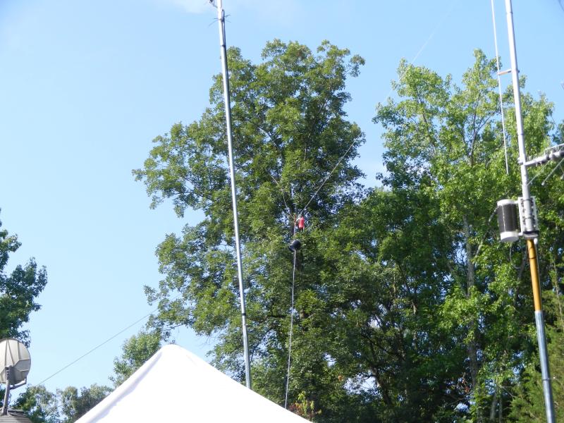
The westward dogleg is not too extreme - maybe 140 - 160 degrees? The photo angle make it look sharper than it is, compounding it with the elevation angle. Overhead view approximation (probably somewhat broader in real life): 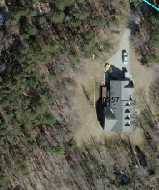
With the new height, 40m is now a bit better on the wire than the MFJ-1796 & 80m is still massively better. Nick |
|
|
|
[#17]
While that angle will slew the radiation pattern somewhat, it is not bad. It is what it is, and should still work well.
|
|
|
|
[#18]
How well would a 80m ocfd work on 60m?
|
|
|
|
[#19]
JT65 = 5BWAS..... just try using this mode to help fill some holes in you logbook.
|
|
|
|
[#20]
Quoted:
How well would a 80m ocfd work on 60m? Dunno... I've worked 60 m with the 75 m portion of fan dipole. I haven't tried 60 m with our club OCFD, but I don't see why it won't work. Yes, you'll need a tuner. |
|
|
|
[#21]
Doesnt an off center fed dipole have to be fed with Ladder line?
|
|
|
|
[#22]
No, not at all. Most feed it with coax.
|
|
|
|
[#23]
To expand upon that: With coax and an appropriate balun for the feed height/angle of legs.
|
|
|
 Win a FREE Membership!
Sign up for the ARFCOM weekly newsletter and be entered to win a free ARFCOM membership. One new winner* is announced every week!
You will receive an email every Friday morning featuring the latest chatter from the hottest topics, breaking news surrounding legislation, as well as exclusive deals only available to ARFCOM email subscribers.

AR15.COM is the world's largest firearm community and is a gathering place for firearm enthusiasts of all types.
From hunters and military members, to competition shooters and general firearm enthusiasts, we welcome anyone who values and respects the way of the firearm.

Subscribe to our monthly Newsletter to receive firearm news, product discounts from your favorite Industry Partners, and more.
Copyright © 1996-2024 AR15.COM LLC. All Rights Reserved.
Any use of this content without express written consent is prohibited.
AR15.Com reserves the right to overwrite or replace any affiliate, commercial, or monetizable links, posted by users, with our own.


