|
[#1]
I built one of these once:http://www.repeater-builder.com/projects/gaasfet.html
Like ten years ago, but IIRC it was a quick build. ETA: If I were to build another, I'd put power injector circuit into it. |
|
|
|
[#2]
Was just looking at that ckt when I went here to see what folks have suggested.
Can you still get the Mitsubishi MGF series FETs? Is there an easily sourced one similar in function in that ckt? I've got some 3SK147[a] , wonder if they would work. I have an old ARR preamp that used a MGF1302 [burned out] Oh wait, the one's I've got are dual gate and not like the MGF1300 series... |
|
|
|
[#3]
What are you wanting it for?
If all you are looking for is gain, a mar-6 will get the job done and at 2 meters, the nf is not bad at 2.8. There are several era devices readily available which are a lot newer and a little better. If you want a good preamp for weak signal, the only kit I am aware of is at Down East Microwave. |
|
|
|
[#4]
Quoted:
What are you wanting it for? If all you are looking for is gain, a mar-6 will get the job done and at 2 meters, the nf is not bad at 2.8. There are several era devices readily available which are a lot newer and a little better. If you want a good preamp for weak signal, the only kit I am aware of is at Down East Microwave. I'm looking for decent, not optimum, noise figure... Not the monolithic amps, too bad... Don't want broad band either. Will look at DEM... |
|
|
|
[#5]
An Australian company has kits as well. I had them bookmarked, but haven't bought anything.
http://www.minikits.com.au/index.php |
|
|
|
[#6]
Preamps are best put up near the antenna not in the shack
|
|
|
|
[#7]
For people like me who can follow instructions when we have a good reason, Kent, WA5VJB has written an excellent article on how to build a preamp with enough parts values to be successful, but broad enough that we can change parts and still get it to work.
http://www.wa5vjb.com/references/preamp-Cookbook.pdf Kent is the VHF editor for CQ mag and has been making rf stuff understandable for years. In any case, any home built preamp should get tested on a noise figure meter, as rarely does the best noise figure adjustment coincide with the best gain settings. If you can get access to the Central States proceedings or those of Microwave Update, there is a lot of info in them about successfully getting a new preamp in the air. For the average ham, the handbook will be useful as usual. |
|
|
|
[#8]
Quoted:
For people like me who can follow instructions when we have a good reason, Kent, WA5VJB has written an excellent article on how to build a preamp with enough parts values to be successful, but broad enough that we can change parts and still get it to work. http://www.wa5vjb.com/references/preamp-Cookbook.pdf Kent is the VHF editor for CQ mag and has been making rf stuff understandable for years. In any case, any home built preamp should get tested on a noise figure meter, as rarely does the best noise figure adjustment coincide with the best gain settings. If you can get access to the Central States proceedings or those of Microwave Update, there is a lot of info in them about successfully getting a new preamp in the air. For the average ham, the handbook will be useful as usual. You're right, he wrote an impressive article and I printed it out last night! |
|
|
|
[#9]
Quoted:
An Australian company has kits as well. I had them bookmarked, but haven't bought anything. http://www.minikits.com.au/index.php They make nice stuff... Here's their 2M preamp, but I can't find any info if they use a dual gate or GaAsFET transistor. MiniKit 2M preamp |
|
|
|
[#10]
My goodness.
For someone who is usually 'splainin stuff to us, did you miss this: "it uses a BF998 mesfet." Or am I all wet? |
|
|
|
[#11]
Quoted:
My goodness. For someone who is usually 'splainin stuff to us, did you miss this: "it uses a BF998 mesfet." Or am I all wet? You are correct... http://www.nxp.com/documents/data_sheet/BF998.pdf Long in the tooth, but looks like a good choice... 46 centavos at Digikey... Now, if somebuddy would suggest a replacement for the MGF [MGF1302, etc] series of GaAsFETs ---that isn't too hot and squirrely, I could fix my old ARR preamp... |
|
|
|
[#12]
Down east 2 m complete kit is $45 and a newer design.
http://www.downeastmicrowave.com/PDF/l-lna.PDF |
|
|
|
[#13]
Is this for SSB or FM? If it is for weak signal work find the lowest noise amp you can afford.
|
|
|
|
[#14]
Quoted:
Is this for SSB or FM? If it is for weak signal work find the lowest noise amp you can afford. No, just need a modest NF preamp to perk up a receiver. |
|
|
|
[#15]
RF Parts Co says they have the MGF1302 in stock if that is all you want:
http://www.rfparts.com/catalogsearch/result/?q=MGF1302 They are $11.95 each. Minimum order is $20. They are a long time supplier of rf parts and I recommend them. Yeah I know: who am I? I would call before placing an order to be sure they have it in stock. |
|
|
|
[#16]
I actually had a preamp working for a while yesterday, the ARR that was burned out.
I took a GaAsFet from an LNA made by California Microwave and put it into the ARR one... The receiver really perked up, from abt 2 uv [it's an AM receiver] to .75 uv for a similar noise vs modulated carrier signal. [The receiver uses an old dual-gate MosFet in it's front end but the rest of the unit is well designed. That's fine for my experimenting, at least now. After a few minutes, while I was listening with headphones to the weak signal, I heard it cut out suddenly. I felt the fet in the ARR preamp and it was real warm. Then I looked at the circuit for the preamp and the source resistor was 10 ohms, with a regulated 5 vdc [thru a 100 ohm] on the drain! I put another in [only had 2 in the CalAmp LNA] and the signal improved but not as before. I started measuring around the FET and found when I de-soldered it, I shorted both the gate and the drain to the eutectic soldered-on ceramic cap . Yet it was still amplifying, just not as well. I will never understand that.... |
|
|
|
[#17]
Quoted:
RF Parts Co says they have the MGF1302 in stock if that is all you want: http://www.rfparts.com/catalogsearch/result/?q=MGF1302 They are $11.95 each. Minimum order is $20. They are a long time supplier of rf parts and I recommend them. Yeah I know: who am I? I would call before placing an order to be sure they have it in stock. I ain't paying no $11 for an MGF... Cheaper on ebay, as low as $5. I just want a cheap near equivalent replacement xistor -current production, in case I decide to make a PCB and build a couple, or blow a few out. |
|
|
|
[#18]
Well, broke down and ordered a handful of Avago ATF-34143 FETs.
I can't see from the data [never figgered all those numbers out], if they have a chance of matching my burned out preamps at 144 mhz. Does anyone know how to interpret S parameter matching data? |
|
|
|
[#19]
Ive got the ramsey one, worked well enough for what I used it for. (VO-52) Ive though about trying to mod it a bit, but have other projects going on.
Cheap enough it's worth a try at least. |
|
|
|
[#20]
Quoted:
Well, broke down and ordered a handful of Avago ATF-34143 FETs. I can't see from the data [never figgered all those numbers out], if they have a chance of matching my burned out preamps at 144 mhz. Does anyone know how to interpret S parameter matching data? Yes, although its been 15 years since I designed amps for a living, and 8 since I taught it at the university. I'd have to dig out a textbook, haven't done hardcore matching on a Smith chart in 8 years. There used to be a student version of Ansoft designer for free download (I used that in class, the students seemed to like it). If you enter the S-parameter file, you can do linear matching networks to check the design. You need non-linear model data (Raytheon-Statz, Curtis Quadratic, or Curtis Cubic) to check non-linear parameters like 3rd order intercept, 1dB gain compression, etc. And those aren't FETs, they look like PHEMTs. If you are going to run them linear you may have problems. Microwave PHEMTS have a bad tendency to suffer from power slump when you bias them for linear operation. We couldn't take a family of curves without sag in the curves due to junction heating. They worked much better in pulsed applications, we even used pulse techniques to get a decent family of curves. Maybe the low frequency ones are better, as the channel dimensions are probably bigger. |
|
|
|
[#21]
Quoted:
Yes, although its been 15 years since I designed amps for a living, and 8 since I taught it at the university. I'd have to dig out a textbook, haven't done hardcore matching on a Smith chart in 8 years. There used to be a student version of Ansoft designer for free download (I used that in class, the students seemed to like it). If you enter the S-parameter file, you can do linear matching networks to check the design. You need non-linear model data (Raytheon-Statz, Curtis Quadratic, or Curtis Cubic) to check non-linear parameters like 3rd order intercept, 1dB gain compression, etc. And those aren't FETs, they look like PHEMTs. If you are going to run them linear you may have problems. Microwave PHEMTS have a bad tendency to suffer from power slump when you bias them for linear operation. We couldn't take a family of curves without sag in the curves due to junction heating. They worked much better in pulsed applications, we even used pulse techniques to get a decent family of curves. Maybe the low frequency ones are better, as the channel dimensions are probably bigger. Quoted:
Quoted:
Well, broke down and ordered a handful of Avago ATF-34143 FETs. I can't see from the data [never figgered all those numbers out], if they have a chance of matching my burned out preamps at 144 mhz. Does anyone know how to interpret S parameter matching data? Yes, although its been 15 years since I designed amps for a living, and 8 since I taught it at the university. I'd have to dig out a textbook, haven't done hardcore matching on a Smith chart in 8 years. There used to be a student version of Ansoft designer for free download (I used that in class, the students seemed to like it). If you enter the S-parameter file, you can do linear matching networks to check the design. You need non-linear model data (Raytheon-Statz, Curtis Quadratic, or Curtis Cubic) to check non-linear parameters like 3rd order intercept, 1dB gain compression, etc. And those aren't FETs, they look like PHEMTs. If you are going to run them linear you may have problems. Microwave PHEMTS have a bad tendency to suffer from power slump when you bias them for linear operation. We couldn't take a family of curves without sag in the curves due to junction heating. They worked much better in pulsed applications, we even used pulse techniques to get a decent family of curves. Maybe the low frequency ones are better, as the channel dimensions are probably bigger. One reason I picked that part is because they acshully are FETs... Just a further evolution of ever increasing performance and variations in fabrication. With a great noise fig and optimized for the UHF band. |
|
|
|
[#22]
The part number you specified, Avago ATF-34143, is not a FET, but a PHEMT. And it is not optimized for UHF according to the data sheets, but S-band and C-band. The S11 magnitude is 0.96 at 500 MHz, you'll have very narrow bandwidth with a simple L network at the input. S12 is not zero either, so you may have a hell of a time keeping it stable at that frequency. If you look at it wrong it is going to oscillate. The optimum S11 for low noise is at the edge of the Smith chart as well, and will be nowhere near 50 ohms at lowest noise figure.
The typical family of curves shown in the data sheet is a set pulse I/V curves. On page 11 of the data sheet, it says the NF data was only experimentally taken at 2 GHZ and higher, the lower frequencies were extrapolated. That usually means they couldn't keep it stable at the lower frequencies. |
|
|
|
[#23]
Quoted:
The part number you specified, Avago ATF-34143, is not a FET, but a PHEMT. And it is not optimized for UHF according to the data sheets, but S-band and C-band. The S11 magnitude is 0.96 at 500 MHz, you'll have very narrow bandwidth with a simple L network at the input. S12 is not zero either, so you may have a hell of a time keeping it stable at that frequency. If you look at it wrong it is going to oscillate. The optimum S11 for low noise is at the edge of the Smith chart as well, and will be nowhere near 50 ohms at lowest noise figure. The typical family of curves shown in the data sheet is a set pulse I/V curves. On page 11 of the data sheet, it says the NF data was only experimentally taken at 2 GHZ and higher, the lower frequencies were extrapolated. That usually means they couldn't keep it stable at the lower frequencies. From the Avago data sheet... Quote... Description Avago’s ATF-34143 is a high dynamic range, low noise PHEMT housed in a 4-lead SC-70 (SOT-343) surface mount plastic package. Based on its featured performance, ATF-34143 is ideal for the first stage of base station LNA due to the excellent combination of low noise fi gure and high linearity[1]. The device is also suitable for applications in Wireless LAN, WLL/RLL, MMDS, and other systems requiring super low noise figure with good intercept in the 450 MHz to 10 GHz frequency range. Note: 1. From the same PHEMT FET family, the larger geometry ATF-33143 may also be considered either for the higher linearity performance or easier circuit design for stability in the lower frequency bands (800– 900 MHz). |
|
|
|
[#24]
About to transplant Avago’s ATF-34143 Gaasfet into a blownup preamp in abt one minuento....
Just have to make a WAG re bias resistors... |
|
|
|
[#25]
OK, it's working.
Used 2 470 pf 0806 caps, one on each source lead, to decouple it from abt 50 MHz up. Used a 20 ohm in the drain lead to help stabilize the high performance FET. Used a 68 ohm in the source to set bias current at abt 20 ma with 5 volts to the drain. The circuit seems highly stable over various input voltages and crude mismatching of input and output. Also stable with no connection to the input or output, observing to ~10ghz. I didn't max the gain so as to achieve better stability. I have no idea re the noise fig but I expect it is quite good based on testing below. Gain is approx 18.6 dB with my circuit mods. Test receiver is an R7000 that has a pretty good sensitivity, a 3khz deviation signal with the receiver filter selected for narrow band, is just perceptible without the preamp at ~160nv... Switching the preamp into R7000 input makes the same signal almost full quieting with a slight background hiss and an occasional 'pop'. I didn't bother to hook a SINAD meter up because this is all the performance I need and want to get back to my main project. In terms of dB, it seems there is a 6 or 7 dB S/N improvement with the preamp, testing in multiple ways. In ordinary terms, this would be like an increase in transmitter power of multiplying it by 4. A 5 watt HT would sound like a 20 watt base station. All with a $1.50 xistor! Wasn't clear above re sensitivity improvement. Should have said a .5 microvolt signal into the R7000 without the preamp, sounds like a .16uv signal with the preamp. That's dramatic. This is the anecdotal experience generally of folks using preamps. In fact, if I can remember back when I was using this particular preamp, I think the new FET has improved it, but as usual, even with the best test equip, there is always some 'subjectivity' in measurements. Very pleased with this transistor's performance and stability, compared to playing with the old timey MGF1300 type transistors. The SMT package of the ATF transistor is very easy to install in place of the classic microwave package like these bad boys... 
|
|
|
|
[#26]
Here's a PCB for a 2 meter preamp I laid out this afternoon when I should have been doing other things...

This preamp can be hooked to an HT to see what weak signals you can REALLY pull in, just don't key it up, or you'll blow the EXPENSIVE $1.50 FET.... The transistor mentioned above can give a super low noise figure [that is shocking to me] and an optional trimmer cap is provided for those who want to experiment to maximize performance. The layout should work beyond 1000 MHz if a correct balun can be designed. It should be a piece of cake to 450 mhz. Higher frequencies may need microstrip lines for best matching, no big deal.... It can be built with careful shopping, mostly on ebay for $15 or less. Even less with a group buy of some of the parts. The actual copper pattern is black, the red and yellow figures are annotations, dimensional outlines, etc, and aren't reproduced on the PCB. The board is designed to be shielded and protected with the lower part of a -small- Altoids tin that may be tack soldered a couple places around the top surface of the PCB to the large and long rectangular pads inside the PCB's perimeter. The yellow outline is the size of the Altoids tin. This thing is small. A lot of the parts can be scrounged from most any device laying around with surface mounted parts, like the caps and chip resistors. In a pinch leaded and small resistors can be substituted. Once parts are collected, it should be able to be built in a hour. The PCB is double sided 1/16" FR4 and should work OK with 1/32 material. No etching is required on the ground plane side. The obvious square and octagonal pads are drilled and connected to the ground plane with a small piece or wire, or tiny rivets. SMA connectors, preferably, are soldered to the ground plane with the center pins connected to the in and out traces. If a feed thru isn't available for the + power, then any header pin or similar can be used, a small leaded capacitor with most any value can be used to bypass RF from the power wire to gnd. The balun can be a ferrite bead or binocular bead scrounged from a TV antenna divider or store bought FT37-43 or something like that. About 12 turns of bifilar [2 pieces of real small enameled wire twisted together] should be good to go. The 3.200" dimension at the top isn't relevant to this bd. Well crap. I was sitting here admiring the layout and noticed something happened to the word "OUTPUT" that should be to the left side of the dwg where the stripline exits the board and where the SMA gets soldered. Fortuneately, I fixed it on my layout in abt 3 seconds... Also, the FET is located where the word 'gate' appears, near the center of the bd. 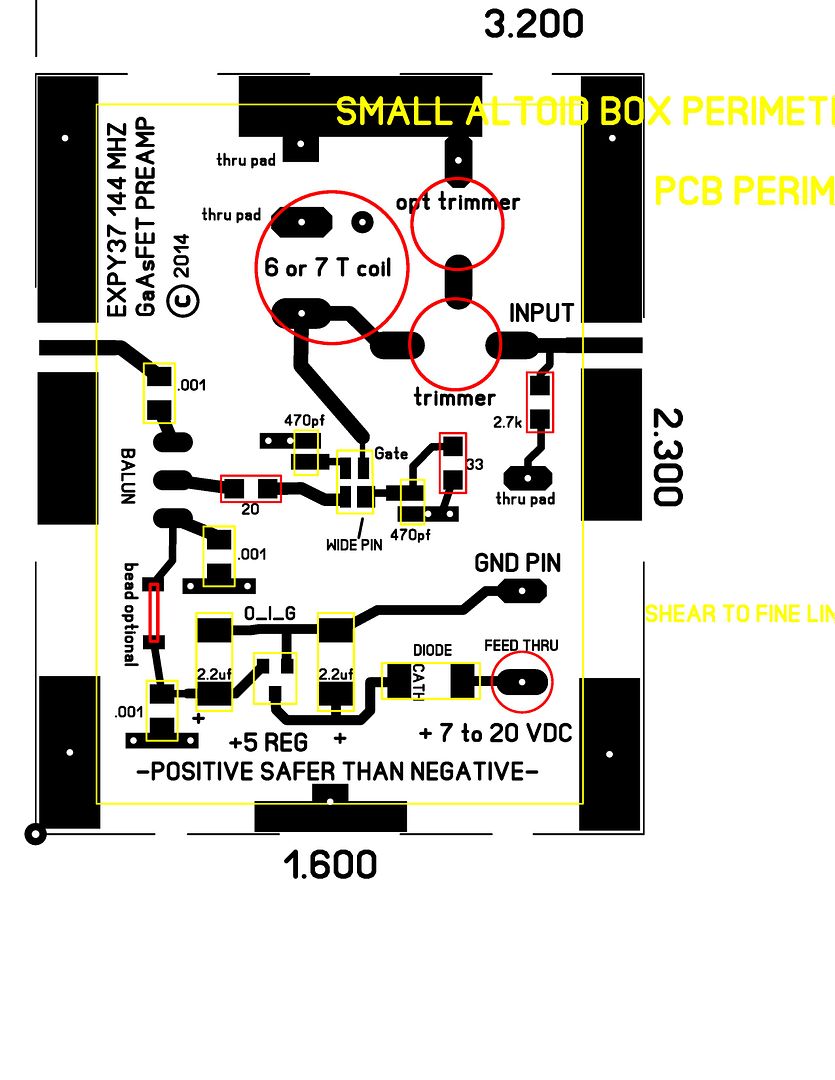
|
|
|
|
[#27]
Made a few boards for other stuff today and made one for this too in the process.
Wound up spending the whole evening until midnight playing with it, it's fascinating to see how you can modify, tweak and tune RF stuff to maximize performance. I had the R7000 nearly full quieting with about .15 microvolts into it. Some mods to the board are going to be necessary, some components are spaced too wide to fit the Altoids can but I thought I measured it carefully. I want to move the coil closer to the FET and relocate one of the source bypass circuits. Also will add some microstrip traces to allow finer tuning and some pads to the output where the toroid is to put trimmer caps to see if I can optimize that. The unit is so sensitive that the noise figure is degraded unless the input circuit is shielded. I thought at first that the noise figure of the preamp was varying but nope, it was noise picked up externally. Tomorrow I'll shield the input coil, etc, and make provision for it in the layout. I can easily hear 3 kHz FM tone modulation in the noise as far down as the HP sig gen goes, -135 dBm. A signal is copy-able as low as .09 microvolts, probably lower, I'm pretty sure. When I first started to tune it, with the coil I used, it was centered around 80 mhz. It should go on 6 meters easily, but I wonder if a low noise preamp would buy much considering there's more natural noise to mask any improvement a preamp would offer. These things are really fascinating. |
|
|
|
[#28]
This could be a good add on to my WXapt station
|
|
|
|
[#29]
Quoted:
This could be a good add on to my WXapt station At 135 MHz, yep, a big difference. I've been playing with it all day and have dishcovered some interesting things... I've been able to get the NF to a point that a tone that's perceptible to the R7000 in the noise, is almost full quieting with the preamp switched in. Also discovered a CHEAPLY implemented method of stabilization, I've never seen implemented before, that might have commercial value. Next, I'll hook a VX7R, and HX370S and maybe some other radios to it and report the results. |
|
|
|
[#30]
Do want. |
|
|
|
[#31]
Couldn't figger out how to change the VX-7R from AM to FM without digging out the manual, and the HX370 was in the truck...
So, the Wouxon was used as another radio. It's receiver is better than the R-7000 but the results were pretty much the same, a signal buried in the noise was copyable with the preamp. So.... The next step is to devise a repeatable and meaningful way to quantify the performance of the preamps. The original blown out ARR 144 MHz preamp with the new transistor performs close to the one I laid out, within a 1/3 of a dB or so, not enough difference to be too meaningful. To make a quantifiable measurement with what I have here, I used a Sinad meter that compares the noise of a signal with [usually] a 1khz tone. This is the industry standard for making the 12 dB S/N measurements for evaluating sensitivity of a receiver. I hooked one up and was pleased to see that it can make noise optimization measurements far easier and better than my ear. And I don't have to listen to the receiver blasting noise and tone all day.
What I discovered is that, there is, -for my R7000, about a 9dB S/N improvement preamp vs no preamp. That surprised me in that by my ear I reckoned there was a 6 dB improvement [and I also improved the preamp in the meantime] In other words, a 9 dB improvement in S/N for a receiver translates to ---GASP! An 8 times power output from a transmitted signal. Folks this ain't a walking around pocket money improvement.... A five watt HT signal now becomes readable as if it were a 40 watt HT! |
|
|
|
[#32]
Here's some boards before I etched them yesterday. Preamp bd is on the middle right. There's two microprocessor bds on there too. A bigger one and a tiny one with lots of features.
The old-timey battery jar holds the etchant and the thing hooked to the Kill-O-Watt is a heater in a quartz tube. Works great and you can see it draws abt 300 watts. Brings the temp of the FeCl to abt 125 F in abt 30 minutes. 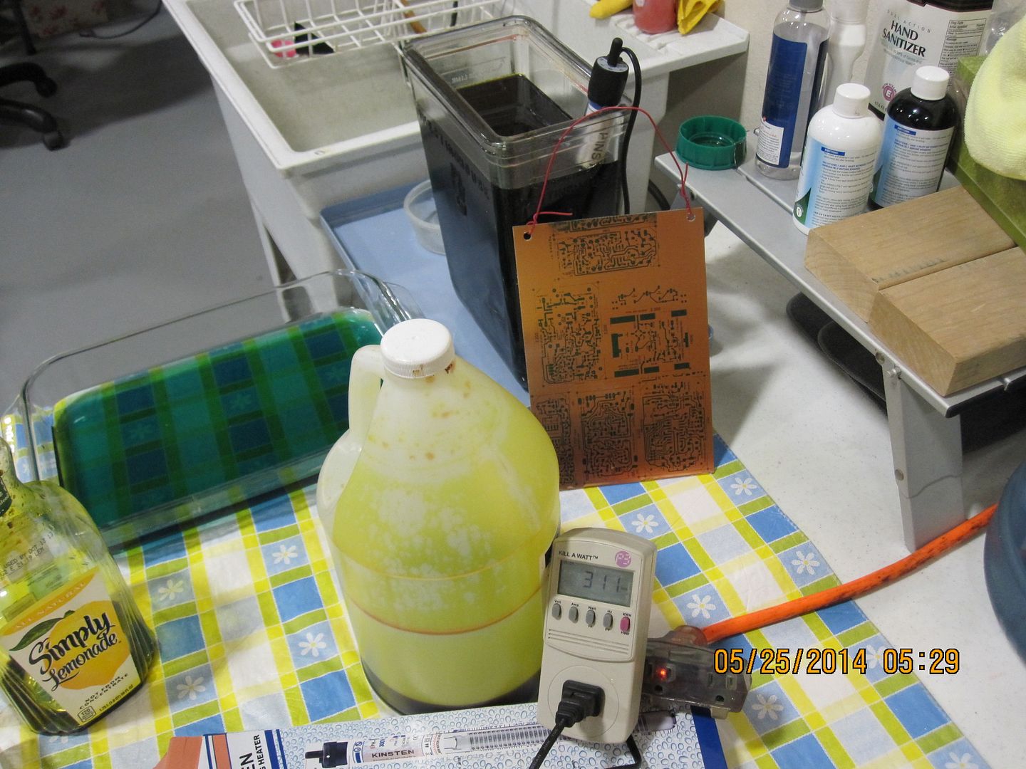
|
|
|
|
[#33]
How does it do down on HF?
Does my getting skipped on the vox interface put me at the top of this pre order list?
|
|
|
|
[#34]
Quoted:
How does it do down on HF? Does my getting skipped on the vox interface put me at the top of this pre order list? What's HF?
|
|
|
|
[#35]
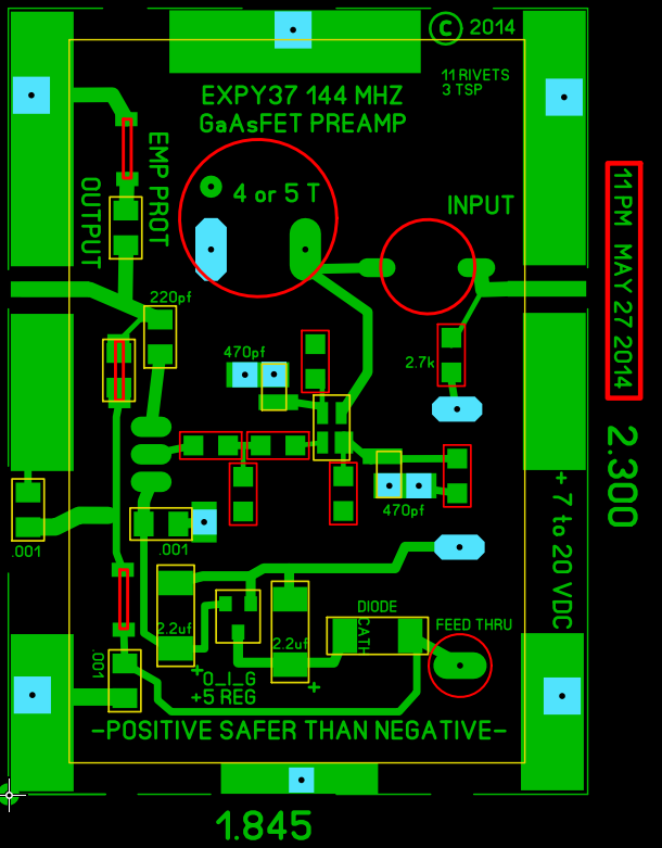
Latest board, subject to additional testing and mods...
|
|
|
|
[#36]
Etched the 2nd board and built it up. Much more refined...
Works great! The R7000 with it has sens of .11 uv w/12 dB SINAD. Very stable, about 18 dB of gain, same noise figure with a current from 7 to 50 ma. FET is rated to abt 25 ma or so. Didn't hurt it. It's interesting that as the input trimmer is adjusted, there is an area of high noise [poor noise figure] and just as that area is passed, the NF improves dramatically and then gently get a tiny bit poorer. Just noticed this this evening and it isn't discernible with the ear. It would allow a quick and dirty tune up with no fancy equipment. The amplifier is very broad and if reception is to be done in an area of strong signals, some sort of pre-selector might be used. |
|
|
|
[#37]
So what kinda of voltage and current draw?
|
|
|
|
[#38]
It uses a 5 volt regulator and in the post above I mention 7 to 50 ma, with no apparent change in NF, but ability to handle stronger nearby signals would -I expect, be better, from a higher intercept point at higher currents.
Take a look at the last layout and there's a resistor pad on the right side where the "+7..." is. Last night I put a hundred ohm pot there and was able to adjust the bias current. Because it was a 100 ohms the lowest I could test was 7 ma. Today, I'll put a 1000 ohm pot and see how little it can draw and still maintain a good NF and report. You raise a good point. It might be useful for portable work to include a switch to select high and low bias currents, depending on the signals around you. I'll add a switch to the next layout that will be on the ground plane side of the board to do just that! The regulator is one of the micro current... [altho any 5 volt regulator will do, like the 78L05, just don't do what I did and use one thinking the pin out is the same as the 7805 ones in the TO220 package, dumb engineers, reversing the pin out and it took me an hour to figger out why the regulator didn't work
....1702 series LDO [low drop out] from Microchip, I think that's what its number is, I like them. The 78L05 quiescent current is IIRC from measuring it, is abt 5 ma, about what it takes to run the PREAMP at low current setting. The 1702 regulators only draw in the microamps. |
|
|
|
[#39]
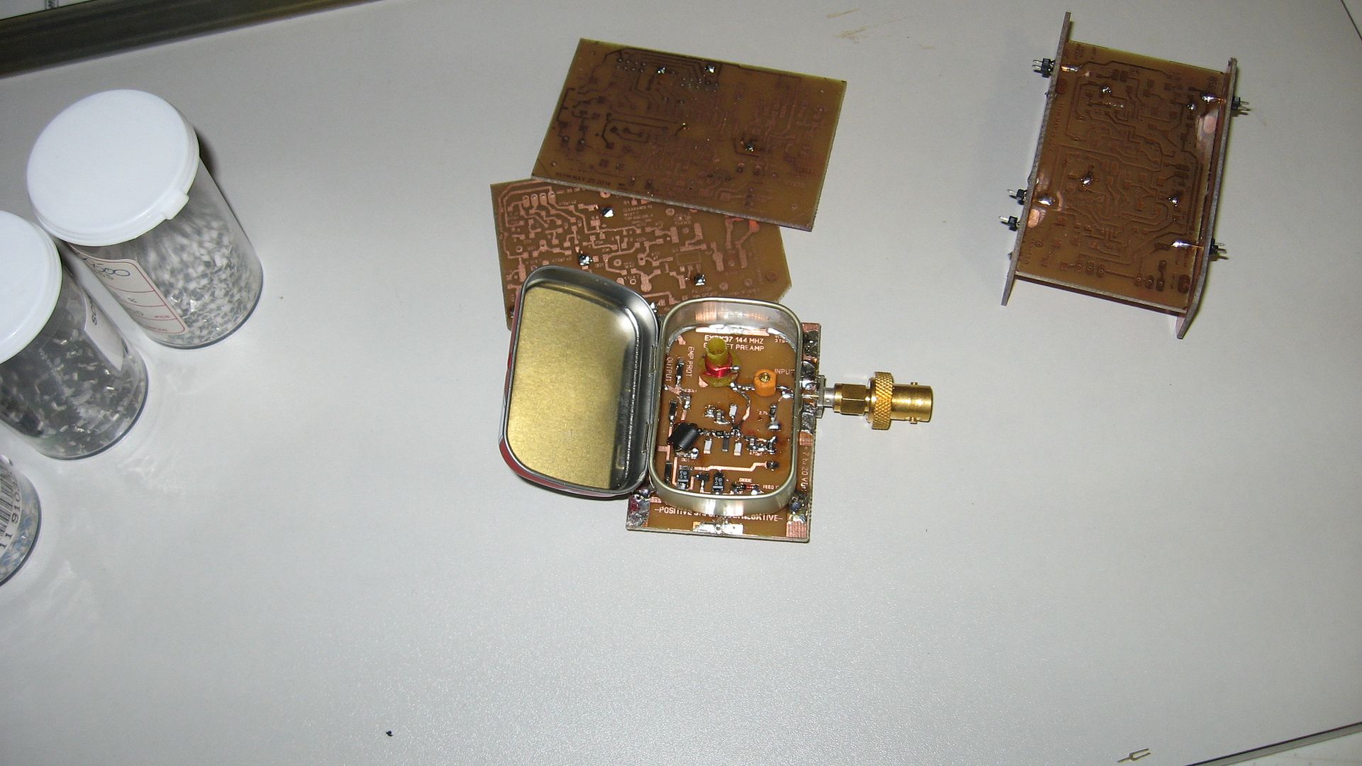
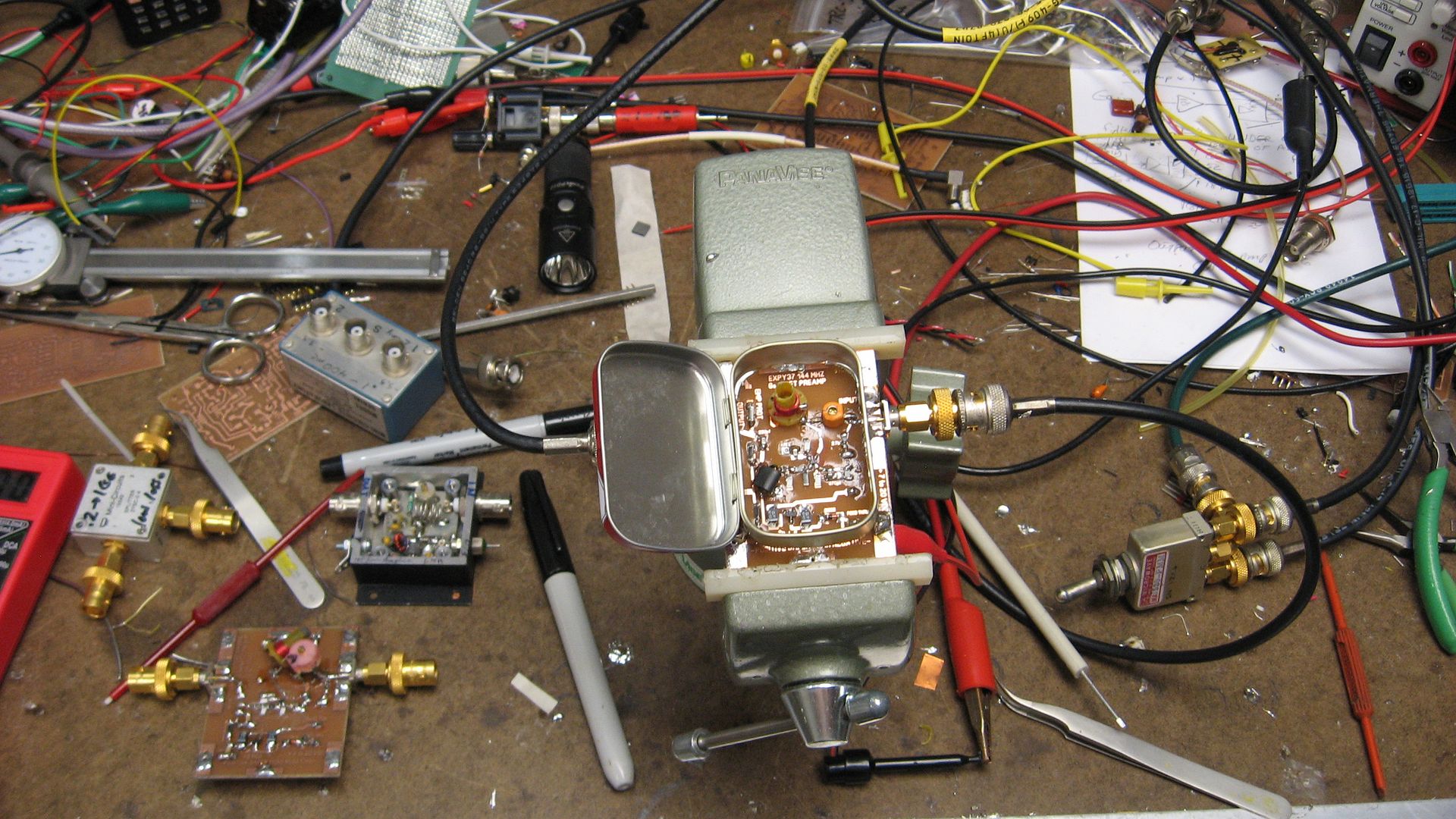
Here's some pix of the completed preamp, at this stage of development.
During the process, I discovered the strange 'interference that was increasing the noise figure of the preamp as much as 6 dB, a LOT... Was due to the newfangled electronic ballasts in the 4 tube fluorescent fixtures in my lab. I knew they were noisy, but the engineers who approved these things much have not been paying a lot of attention when they approved them vs RFI. I wonder how many of the rest of us have issues directly traceable to ballasts? I could place my hand on the output, the gold SMA to BNC connector on the left and pretty much suppress the noise and see a full performance NF. The Altoids box eliminates all the noise. The noise can be seen on a high performance spectrum analyzer just above the analyzer's noise floor at 150 MHz, as sort of a Gaussian response. It's surprising considering the short lead length, that the preamp is so sensitive that it is killed by the lighting. Even lights in another room are detectable in the SINAD meter response. In fact the preamp with a weak signal source might make the basis for a short range intrusion detector. This is the 'SMALLS' Altoid can, the wee little one... 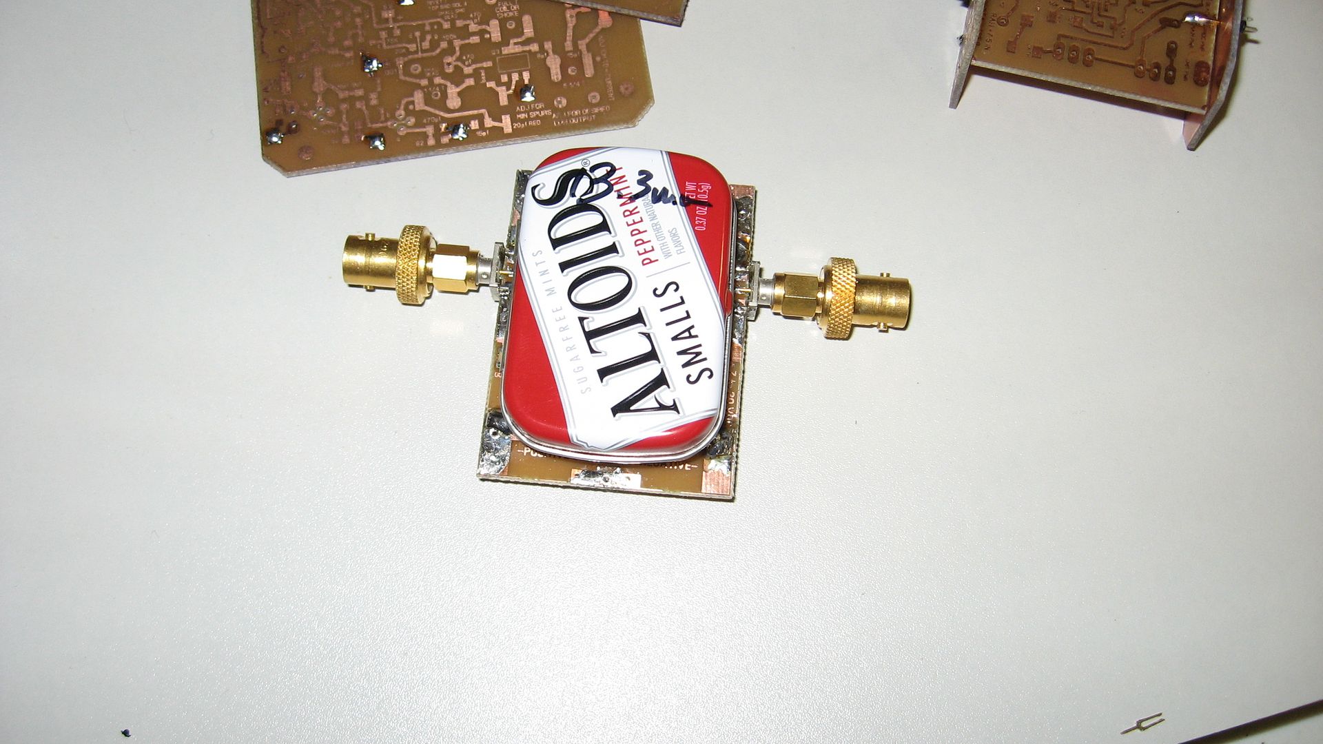
|
|
|
|
[#40]
The bottom of the can got punched with a Diacro punch, abt 3/4", then a hand nibbler was used to cut the bottom out cleanly. Harbor Freight has nibbler. Or Dremel tool can be used.
The can is tack soldered at the connectors and at the bottom, that seems sufficient. There's some additional discoveries and info when I get time to post... |
|
|
|
[#41]
Oh, GCW asked about current draw.
I could run the preamp with best noise figure, in addition to the data above, down to a current draw as low as ~700 MICROAMPS! Without degrading the NF as measured on the Sinad meter. Below that down to 400 or 500 microamps, the NF degraded by abt 2 dB. So a switch to conserve power, or raise the intercept point, might be a useful addition, as GCW stimulated. |
|
|
|
[#42]
In the last pix above, the ARR and the first iteration of the project preamp, are to the right of the preamp in the vise.
If anyone finds this interesting ---judging by all the comments everybuddy is...
...and wants to pursue making low noise measurements, I've got a lot of ideas how a shack measurement system can be set up for very little cost. |
|
|
|
[#43]
I suck at RF and I have almost no clue whats happening in this thread but I want to
ETA - I may not suck as much as I think I do but I always feel like theres more to it than I think... |
|
|
|
[#44]
Quoted:
I suck at RF and I have almost no clue whats happening in this thread but I want to ETA - I may not suck as much as I think I do but I always feel like theres more to it than I think... No time like the present to ask questions and see if you have an interest... |
|
|
|
[#45]
Quoted:
No time like the present to ask questions and see if you have an interest... Quoted:
Quoted:
I suck at RF and I have almost no clue whats happening in this thread but I want to ETA - I may not suck as much as I think I do but I always feel like theres more to it than I think... No time like the present to ask questions and see if you have an interest... Alright here goes.... I went through college as a computer engineer with much work on the electrical engineering side of things but professionally I'm a computer security R&D guy. Circuits aren't a mystery to me but I'm not great at them any more. My understanding of your amplifier thusly is......... You have an input signal/s of various frequencies of whatever your antenna is picking up. These are AC/sine waves of very minute voltages? What voltages are we talking about here? So with all these various frequencies inbound do you try to filter them out? And you are using an inductor/capacitor network or traces on the board to do so? When you "filter out" a signal where does it go? Does it just get grounded out or converted into DC that you can block with a capacitor? Okay... At this point the unwanted frequencies are gone and we are down to the ones we want. This is fed into the gate of the FET? Now the power going into the source FET is from a DC source? Whats the voltage going into this FET? And then the drain from the FET is fed into the radio? I think I'm seeing some circuit designs that have resistors or pots on the source and drain of the FET which would allow you to control voltages some. What voltages are we talking about here? Does the FET invert the frequency 180 degrees? Does that even matter? Is there or what happens if the gain is too great? Does the amplified signal just get clipped? |
|
|
|
[#46]
Quoted:
Alright here goes.... I went through college as a computer engineer with much work on the electrical engineering side of things but professionally I'm a computer security R&D guy. Circuits aren't a mystery to me but I'm not great at them any more. My understanding of your amplifier thusly is......... You have an input signal/s of various frequencies of whatever your antenna is picking up. These are AC/sine waves of very minute voltages? What voltages are we talking about here? <span style="color: blue;">Yes, these are 'RF signals, just the same as your VHF rig would pick up. The level of the voltages is in the millionths of a volt, we call this microvolts. Or 'uv'. For the level of signals we're testing with, or weak signals coming into your antenna. So with all these various frequencies inbound do you try to filter them out? And you are using an inductor/capacitor network or traces on the board to do so? When you "filter out" a signal where does it go? Does it just get grounded out or converted into DC that you can block with a capacitor? <span style="color: blue;">Good questions! All properly designed receivers have 'input tuned circuits' that filter out [reject] the zillions of extraneous signals coming in off the antenna. Doesn't matter at what frequency. Where do they go, if you put your hands over your ears, to block out sounds, the same place. The signals never get thru the filter [as much], but unlike sediment in a water filter, the miniscule amount of energy in those 'blocked' signals, is either reflected back into space, to be dissipated as an almost immeasurable amount of heat energy, or due to the Q factor or resistive losses in your filter, the unwanted signals are dissipated as heat, there. As far as a capacitor, at the frequencies we're talking about, tuned circuits are usually comprised of a network of capacitiors and inductors. Ergo, why you see coils and caps on the RF circuit boards. For UHF and higher frequency signals, there are too many issues with lumped constant components, caps, and coils, so usually they are implemented as traces on the printed circuit board, called 'microstrip', having generally well defined size and characteristics.. Okay... At this point the unwanted frequencies are gone and we are down to the ones we want. This is fed into the gate of the FET? Now the power going into the source FET is from a DC source? Whats the voltage going into this FET? And then the drain from the FET is fed into the radio? I think I'm seeing some circuit designs that have resistors or pots on the source and drain of the FET which would allow you to control voltages some. What voltages are we talking about here? <span style="color: blue;">Right! On the preamp board I laid out, there is a coil and an input capacitor, variable, to allow for some tuning, but there are only two 'poles' [hell, I don't know how many...]
...and the input filtering is very broad. Correct, the signals next go to the gate. The amplifier is 'biased' with a DC voltage, provided in this case by the 5 volt regulator. From the spec sheets for the FET, we see that the design specs call for about 3 volts across the drain and source, or in a tube, the plate to cathode. The drain is equivalent to the plate of a tube and there is a circuit to roughly match the FET drain impedence to the 50 ohm coax. In the pix preamp, it's the black thing to the left of the FET. In my case cause I have bags of them, it's a small binocular ferrite bead with about 6 turns of bifilar wire wrapped thru the eyes to step the high impedence of the FET to ~50 ohms. It isn't critical and doesn't matter if there is much loss at this point because the noise figure is already set by the input network and the characteristics of the FET. As far as pots on various circuits, they are likely there allowing for adjustments to FET bias points. As mentioned above, I put an ultimately 5k pot, in the source lead to adjust the bias current to the 100's of micro-amperes to see what little power could be drawn and still amplify with a good noise figure. Does the FET invert the frequency 180 degrees? Does that even matter? Is there or what happens if the gain is too great? Does the amplified signal just get clipped? <span style="color: blue;"> Yes it does and no is doesn't make a rat's behind's worth of a difference, except to folks in academia.
If the gain is too great, the receiver that's hooked to the preamp suffers the same fate as if EMP hits it, the front panel knobs of the receiver get blown off into the operator's belly. Oh wait, that's not right... It isn't going to happen in this instance, so we don't have to worry abt it. Low level signals that are too large for the dynamic range of the following stages, do get clipped. Next questions.... Quoted:
Quoted:
Quoted:
I suck at RF and I have almost no clue whats happening in this thread but I want to ETA - I may not suck as much as I think I do but I always feel like theres more to it than I think... My understanding of your amplifier thusly is......... You have an input signal/s of various frequencies of whatever your antenna is picking up. These are AC/sine waves of very minute voltages? What voltages are we talking about here? <span style="color: blue;">Yes, these are 'RF signals, just the same as your VHF rig would pick up. The level of the voltages is in the millionths of a volt, we call this microvolts. Or 'uv'. For the level of signals we're testing with, or weak signals coming into your antenna. So with all these various frequencies inbound do you try to filter them out? And you are using an inductor/capacitor network or traces on the board to do so? When you "filter out" a signal where does it go? Does it just get grounded out or converted into DC that you can block with a capacitor? <span style="color: blue;">Good questions! All properly designed receivers have 'input tuned circuits' that filter out [reject] the zillions of extraneous signals coming in off the antenna. Doesn't matter at what frequency. Where do they go, if you put your hands over your ears, to block out sounds, the same place. The signals never get thru the filter [as much], but unlike sediment in a water filter, the miniscule amount of energy in those 'blocked' signals, is either reflected back into space, to be dissipated as an almost immeasurable amount of heat energy, or due to the Q factor or resistive losses in your filter, the unwanted signals are dissipated as heat, there. As far as a capacitor, at the frequencies we're talking about, tuned circuits are usually comprised of a network of capacitiors and inductors. Ergo, why you see coils and caps on the RF circuit boards. For UHF and higher frequency signals, there are too many issues with lumped constant components, caps, and coils, so usually they are implemented as traces on the printed circuit board, called 'microstrip', having generally well defined size and characteristics.. Okay... At this point the unwanted frequencies are gone and we are down to the ones we want. This is fed into the gate of the FET? Now the power going into the source FET is from a DC source? Whats the voltage going into this FET? And then the drain from the FET is fed into the radio? I think I'm seeing some circuit designs that have resistors or pots on the source and drain of the FET which would allow you to control voltages some. What voltages are we talking about here? <span style="color: blue;">Right! On the preamp board I laid out, there is a coil and an input capacitor, variable, to allow for some tuning, but there are only two 'poles' [hell, I don't know how many...]
...and the input filtering is very broad. Correct, the signals next go to the gate. The amplifier is 'biased' with a DC voltage, provided in this case by the 5 volt regulator. From the spec sheets for the FET, we see that the design specs call for about 3 volts across the drain and source, or in a tube, the plate to cathode. The drain is equivalent to the plate of a tube and there is a circuit to roughly match the FET drain impedence to the 50 ohm coax. In the pix preamp, it's the black thing to the left of the FET. In my case cause I have bags of them, it's a small binocular ferrite bead with about 6 turns of bifilar wire wrapped thru the eyes to step the high impedence of the FET to ~50 ohms. It isn't critical and doesn't matter if there is much loss at this point because the noise figure is already set by the input network and the characteristics of the FET. As far as pots on various circuits, they are likely there allowing for adjustments to FET bias points. As mentioned above, I put an ultimately 5k pot, in the source lead to adjust the bias current to the 100's of micro-amperes to see what little power could be drawn and still amplify with a good noise figure. Does the FET invert the frequency 180 degrees? Does that even matter? Is there or what happens if the gain is too great? Does the amplified signal just get clipped? <span style="color: blue;"> Yes it does and no is doesn't make a rat's behind's worth of a difference, except to folks in academia.
If the gain is too great, the receiver that's hooked to the preamp suffers the same fate as if EMP hits it, the front panel knobs of the receiver get blown off into the operator's belly. Oh wait, that's not right... It isn't going to happen in this instance, so we don't have to worry abt it. Low level signals that are too large for the dynamic range of the following stages, do get clipped. Next questions.... TEST FOR DISAPPEARED ANSWERS |
|
|
|
[#47]
Thanks for answering my questions. Turns out I understand most of whats going on just fine. For some reason I keep thinking theres some magic happening that I'm missing.
|
|
|
|
[#48]
Title says 'Group build' sooooo... 
|
|
|
|
[#49]
Took some time to experiment with the present circuit layout to see how high I could move it toward 440 MHz and retain a good noise figure.
I was able to retune it to about 340 MHz with an excellent noise figure and a sensitivity of about .1 microvolt using the Icom R7000 test receiver. Beyond that the preamp had an increasing NF and there was no instability. What I plan to do is re-layout the board eliminating the lumped constant components and use edge-line in a micro-strip configuration, the edge-line possibly being 2 parallel silver wires I already have in the junk box. The wires may meander from the ground plane at the top of the board as shown in the drawing here, with added rivets at ground, directly to the gate of the FET. Under the silver wires, I'll try to efficiently couple the signal to them with a sort of microstrip directional coupler arrangement, using a parallel 70 ohm line fed near the FET from a 50 ohm line that comes from the input SMA connector. The 70 ohm line will be terminated in a 50 ohm chip resistor and the silver wires formed as necessary to effectively couple. I'll try to get the tuning-layout close to the ball park but any good performance in the 500 MHz range will suggest the circuit can be optimized for 440. To get a good match, I'll couple from the 50 to the 70 ohm lines with a tiny trimmer cap, eventually going to a high performance high Q ceramic miniature piston type. Later it will be 10319,430 printed somehow. To tune the double silver wire resonator, a similar capacitor may do the trick, or an appropriate sized pad on the PCB may do. In case this doesn't work, I'll put lines on the board to couple directly to the silver wires via a capacitor at about 25% from the ground end. Suggestions? |
|
|
|
[#50]
So when you say optimize it for 500MC how will that effect the performance at 144MC?
Also when is the group buy for the kit going to be ready? My WxSat station needs moar ears. |
|
|
 Win a FREE Membership!
Sign up for the ARFCOM weekly newsletter and be entered to win a free ARFCOM membership. One new winner* is announced every week!
You will receive an email every Friday morning featuring the latest chatter from the hottest topics, breaking news surrounding legislation, as well as exclusive deals only available to ARFCOM email subscribers.

AR15.COM is the world's largest firearm community and is a gathering place for firearm enthusiasts of all types.
From hunters and military members, to competition shooters and general firearm enthusiasts, we welcome anyone who values and respects the way of the firearm.

Subscribe to our monthly Newsletter to receive firearm news, product discounts from your favorite Industry Partners, and more.
Copyright © 1996-2024 AR15.COM LLC. All Rights Reserved.
Any use of this content without express written consent is prohibited.
AR15.Com reserves the right to overwrite or replace any affiliate, commercial, or monetizable links, posted by users, with our own.