|
Posted: 3/12/2024 10:41:08 AM EDT
[Last Edit: aa777888-2]
Given the frequency (ha, a pun!
By all means, please submit additions, corrections and modifications for consideration. Don't forget spelling mistakes! Once we have a consensus on this perhaps it can become a tacked thread for future reference. ===================================================================== Introduction 1. What is NVIS? Near vertical incidence skywave (NVIS) is a special case of high frequency (HF) radio skywave propagation. With NVIS, RF radiation that is radiated straight up will be refracted by the F2 layer of the ionosphere nearly straight back down. This will cover a circular region between 100 and 400 miles in radius from the transmitter, depending upon ionospheric conditions. 2. What is NVIS good for? NVIS fills a niche where the range of ground wave propagation is too short and the normal skywave propagation is too far. It’s also very useful in rugged terrain where HF ground wave or VHF line-of-sight propagation will not work well. 3. Can I use NVIS propagation any time I want? No. NVIS is only available in HF amateur radio bands when the proper ionospheric conditions are present. This is no different than other forms of HF skywave propagation, such as grey line propagation. 4. Do I need anything special to use NVIS propagation? Sort of. You need two things, neither being particularly special. First, you need knowledge on how to determine whether NVIS conditions are likely to be present in one or more HF amateur radio bands. Second, you need an antenna that will radiate horizontally polarized waves reasonably efficiently in an upward direction. Antenna Requirements 5. Do I need a special antenna? Not really. Antennas suitable for NVIS need two characteristics. First, they must be horizontally polarized. Thus pretty much any horizontal wire antenna will work. Second, they must not be higher than ¼ wavelength above the ground in order to ensure that sufficient energy is radiated in an upward direction. Note that the antenna does not have to be perfectly horizontal in a physical sense, just horizontally polarized with a pattern that radiates reasonably well upwards. For instance, moderately sloped end-feds and inverted V type antennas can be used. 6. Will one of the “special” NVIS antennas shown on various websites and military handbooks work better than a run-of-the-mill dipole? No. The “special” antennas are not really special at all. They are usually simple, multi-band (“fan”) dipoles. 7. Does my antenna have to be mounted very close to the ground? No. Anything under ¼ wavelength high will work. The closer the antenna is to ¼ wavelength high the more efficient it will be. This is not to say a very low antenna will not work. One of the advantages of NVIS is that low antennas will function reasonably well. But a low antenna will not work as well as a higher one (without exceeding ¼ wavelength high). 8. Will my DX antenna work for NVIS? Assuming it is a horizontal wire antenna then almost certainly it will. Since most NVIS conditions occur on the 40 through 160 meter bands (there are exceptions), and since most amateurs have difficulty placing such antennas higher than ¼ wavelength above the ground, the antenna you have will be fine. On the other hand, exceeding 10 meters in height on a 40 meter dipole is not that difficult, so that may be an issue if 40 meter NVIS operation is desired. 9. Do I need a counterpoise? Not normally. However, soil and ground conditions vary significantly throughout the world. A counterpoise may be helpful in improving antenna efficiency in an upward direction. If you are having trouble achieving success it may be worth a try. Frequency Selection 10. I can just jump on 40, 60 or 80 meters with a low antenna and that’ll automatically be NVIS, right? Unfortunately, no. It all depends on what the F2 and D layers of the ionosphere are doing. You might get lucky, of course. 11. What is the highest frequency I can use for NVIS? The highest frequency that can be used for NVIS is called the “critical frequency” or “foF2”. This is the frequency below which the F2 layer of the ionosphere will refract HF radio signals. Frequencies above foF2 will not be refracted by the F2 layer. Note: do not confuse foF2 with “maximum usable frequency” (MUF), which is a measure of what the highest usable frequency is for skywave propagation other than NVIS. 12. What is the lowest frequency I can use for NVIS? The lowest frequency that can be used for NVIS is the “D layer absorption frequency”, or “lowest usable frequency” (LUF). Just like foF2 depends on the condition of the F2 layer, the LUF depends on the condition of the D layer of the ionosphere. 13. How does anyone know what foF2 and LUF are? There is a worldwide network of ionospheric monitoring stations. These stations use a device called an ionosonde to measure ionospheric conditions. If you’ve ever noticed a signal that sweeps fast across the ham band that is probably an ionosonde station taking measurements. The output of these measurements is a chart called an ionogram. Sample ionogram shamelessly copied from https://www.idahoares.info/tutorial_hf_nvis_band_selection.php: 14. Where can I find ionograms? https://giro.uml.edu/ https://www.ngdc.noaa.gov/stp/IONO/rt-iono/ https://www.digisonde.com/stationlist.php 15. How can I learn how to read an ionogram? There is an excellent top level tutorial here: https://www.idahoares.info/tutorial_hf_nvis_band_selection.php 16. Ionograms are a pain in the butt to find and read. Is there an easier way? There is for foF2. There are a number of websites that aggregate ionosonde data and display a near real-time map of foF2. Examples include: https://prop.kc2g.com/fof2/ https://www.sws.bom.gov.au/HF_Systems/6/5 Unfortunately there is no similar mapping being done for LUF. Operating Considerations 17. What is the best band/frequency to use? Whichever band and frequency is closest to foF2 without exceeding foF2. The closer you operate to foF2 the less D layer absorption there is. 18. What can I do if no ham bands are between LUF and foF2? All you can do is wait for conditions to change. Or rely on a different propagation method if possible (e.g. ground wave). That is the problem with amateur radio frequency allocations. They are designed to minimize the effects of harmonic interference on other services and not to provide an opportunity to obtain NVIS conditions 24/7. 19. I’m operating down close to, but not below LUF, yet it is not working. Why? There is not enough power and/or antenna gain to overcome the amount of D layer absorption. And ionograms are not real-time, perfect, or hyper-local. In other words, “your mileage may vary”. 20. How much RF power do I need? The rule of thumb is approximately 20W minimum, and 100W should be plenty. More than QRP power levels are generally required to overcome D layer absorption particularly if the operating frequency is not right up near foF2. This is not to say that people have not made contacts with 5W or even 1W, but obviously QRP working conditions are much more challenging. 21. I’m in a rag chew net in the evening on 40 or 80 meters. This must be NVIS, right? Not necessarily. If the big guns with 500W or more are the only stations that are easily copied then it may all be ground wave and the amplifiers are doing the grunt work. Similarly, if even a QRO station with the low end-fed or OCFD or dipole is not getting through well, but the folks with high dipoles or inverted L’s are doing OK, again it might be ground wave and not NVIS. 22. How the heck can I tell if it’s NVIS or not? If those with low antennas and/or low power are doing nearly as well as those with high antennas and/or high power, then that’s a good sign it is NVIS. If you take a look at the ionospheric data and you are operating below foF2 and not too far down towards LUF then that’s also a good sign. If you are operating right up near foF2 and the band turns off like a switch, then check to see where foF2 went. If it went down below your operating frequency then it was probably NVIS, but not anymore! 23. NVIS is a requirement for super-über-practical-tactical communications, right? Not at all. It’s just one tool in the toolbox. And, since the ionosphere and amateur band allocations do not allow for 24/7/365 availability of NVIS, more often than not it’s important to have other tools available, such as CW, small signal modes like JS8, etc. |
|
|
|
|
[#1]
Awesome! Thank you! This needs tacked.
|
|
|
|
OH, USA
|
[#2]
For a practical working example of this, search for "75M Cloud Burner" (or 80M).
Years ago a bunch of us hung out on 3892 during the late morning/early afternoon. 3s, 8s, 9s and 2s...with the exception of our friend Don the one lone 4-lander, the rest of ya can hit the damn road.  My antenna for the net was a loaded dipole cut for resonance around 3900. The inner (non-loaded) section resonated around 18.130. It was about 35ft in the air. Positioned below it and buried a few inches in the ground was a reflector element. What you effectively had with this was a 2el Yagi which radiated straight up. Put a pin slightly south of Cleveland then draw a circle with about 300mi radius around it. Within the circle, the Cloud Burner worked so well for this application that I often didn't need to turn the amp on. Bonus was the 17M section. It favored central and south America. A good amount of DX was worked. The other 3.5MHz antenna at the installation was a 6BTV. That one was the DX antenna and was far enough off resonance from the other (tuned for ~3.56MHz) that they really didn't interact. |
|
|
|
[Last Edit: Harlikwin]
[#3]
Really good job.
The only things I'd add are the following. MUF changes alot throughout the day and night, so there is very likely a time it will intersect with a HAM band you can operate on (usually 40/60/80). So its really important to understand how time of day influences the MUF at your lattitude. I.e. muf will be lowest pre-dawn, and then rise steadily through the day, and then start going back down. There used to be charts for this in the old antenna books. Antennas, as mentioned, they aren't really "special" but you aren't gonna build an antenna that works well for NVIS and DX, you will need a dedicated antenna 1/4wl or less. Also you can sometimes "tilt" a dipole to get a bit more oomph in a specific direction, but its not a huge thing. |
|
|
|
|
[#4]
This is awesome! NVIS is probably my favorite mode of operation. I really need to get another HF rig!
|
|
|
|
|
[#5]
The antenna has to be horizontally polarized?
I know it is better to have the higher tale off angle...... but are you saying that a ground mounted 1/4 vertical is simply never going to work? |
|
|
|
|
[Last Edit: Harlikwin]
[#6]
Originally Posted By Shootindave: The antenna has to be horizontally polarized? I know it is better to have the higher tale off angle...... but are you saying that a ground mounted 1/4 vertical is simply never going to work? I mean never say never but look at an antenna pattern for a vertical, there is a huge null going straight up which is where you want to be for NVIS, I mean look at the following figure, you are like 15db down with 1/4 WL and that takeoff angle will still be better for "long range" NVIS, not local. .mil will bend their whips or set them up at horizontal angles to do it. You can find pics of humvees and other vehicles with the whip bent forward so it acts as a better NVIS radiator. Its still mostly a shit way to do it, but better than nothing. You see all sorts of better dedicated mobile NVIS designs these days.  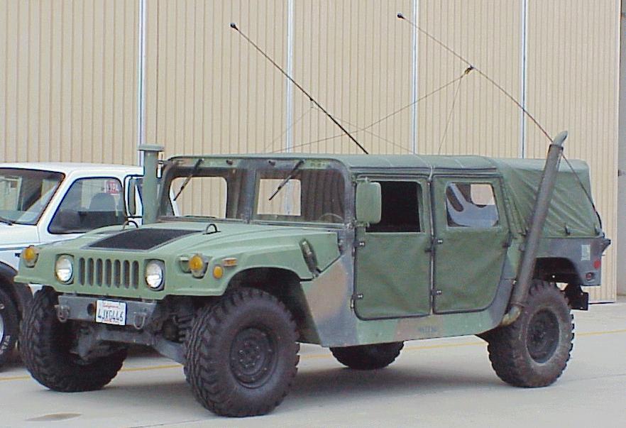
|
|
|
|
|
[#7]
Originally Posted By KB7DX: Awesome! Thank you! This needs tacked. FPNI Well done |
|
|
|
OH, USA
|
[#8]
Current yard is ~250x660ft, with the longer dimension running E-W. House is around 120ft into the lot.
I may convert a couple close-in multiband dipoles to NVIS use on 80/60/40. Don't know if I'll put reflectors underneath them. Out in the far pasture/orchard area I'm thinking about putting up a 6BTV, another BTV modified for 11/12/17/30/60M and several satellite active elements for the other bands. The BTVs will be spaced 1/4w at 10.125MHz and a phasing harness will be used for selecting the pattern. Likewise with the other active driven elements. As noted earlier, shouldn't be any interaction with the NVIS setup, owing to both distance and polarity. |
|
|
|
[#9]
Originally Posted By KB7DX: Awesome! Thank you! This needs tacked. Originally Posted By Harlikwin: Really good job. Originally Posted By 3one5: This is awesome! Originally Posted By Colt653: Well done Originally Posted By Harlikwin: Antennas, as mentioned, they aren't really "special" but you aren't gonna build an antenna that works well for NVIS and DX, you will need a dedicated antenna 1/4wl or less. This is already covered in the FAQ. As written in the FAQ, most folks have trouble getting their antennas that high and therefore are GTG as is. Those who are doing better than that do need to do something different. I didn't want to bog down the FAQ with a million different ideas. Lower antennas, higher counterpoises, or even what I did, which was to build a modified 40M half square which has a nearly hemispherical pattern even though it is up nearly 20M high. Originally Posted By AnalogKid: I may convert a couple close-in multiband dipoles to NVIS use on 80/60/40. |
|
|
|
OH, USA
|
[#10]
Originally Posted By aa777888-2: What do you think you need to do to convert them? Drop the elevation, mainly. They're pretty high at the apex. I hear things in FL and GA a lot better on 75 than I do nearby states like PA or WV - so they aren't NVIS optimized. |
|
|
|
[Last Edit: Harlikwin]
[#11]
Originally Posted By aa777888-2: Thank you! So are you saying that your 40M dipole is up higher than 10M, and that your 80M dipole is up higher than 20M? If so then you are a definite minority, and you have some nice antennas there! This is already covered in the FAQ. As written in the FAQ, most folks have trouble getting their antennas that high and therefore are GTG as is. Those who are doing better than that do need to do something different. I didn't want to bog down the FAQ with a million different ideas. Lower antennas, higher counterpoises, or even what I did, which was to build a modified 40M half square which has a nearly hemispherical pattern even though it is up nearly 20M high. What do you think you need to do to convert them? Nah, maybe I missed it. but my NVIS antenna (multiband) is on the ground I.e. about 5meters, my DX antenna (multiband) is up high like 20m. For portable ops, I just setup what I need. G5RV or derivative in both cases I cut the lower one to tune better on 40/80. Cuz well lol 20 ain't gonna work where I live. Upper one is tuned for 20 optimally. |
|
|
|
|
[#12]
Nope - not an old school tag.
I need to put my 60m antenna up again. |
|
|
|
|
[Last Edit: Harlikwin]
[#13]
Originally Posted By Amish_Bill: Nope - not an old school tag. I need to put my 60m antenna up again. Honestly its not a great band for HAM's. You'd be better off with 80/60/40 multiband. |
|
|
|
|
[#14]
very nice write up!
|
|
|
|
|
[Last Edit: K9-Bob]
[#15]
Hang on the CBer's will be along shortly to crap on this thread.
Excellent post OP. |
|
|
|
|
[#16]
Thanks, gents!
|
|
|
|
|
[#17]
This deserves to be converted into a slide deck.
|
|
|
|
|
[Last Edit: CoyoteGray]
[#18]
Some information on the antenna I'm using and my results.
The antenna is an iCom AH-710 Folded Dipole setup as an inverted V. The center is at about 25 feet, and each end is at about 8 feet. Its setup close to north-south. It is very quiet, and I get very good results within about 800-1000 miles east and west from Oklahoma. I can get just over the border into Canada and down southern Texas. It drops off quickly after that. Coasts are out of the question. ETA: This performance is with Digitial such as Winlink. Realistic voice is about half unless the other party has a yagi, etc. but a strong signal in that area. It has been a good setup for a horizontal antenna in a relatively small space. It's been in the air for about 5 years and has withstood several ice storms, etc. I just put up a 43-foot vertical and it's not nearly as quiet and doesn't perform as well in the area the Folded Dipole covers but one of my first contacts was just under 4000 miles in the Azores Islands. They complement each other. |
|
|
|
TN, USA
|
[Last Edit: taliv]
[#19]
for those of you running low wire antenna for NVIS, do you use reflectors? i.e. wire(s) running parallel to the radiating element a few feet below and perhaps 5% longer
|
|
|
TN, USA
|
[Last Edit: taliv]
[#20]
ok, here's an NVIS challenge... with paint diagram!
my QTH is on a mtn top. pretty close to 40* slopes on both sides, valleys and then a peak west of me at 3000' and east of me at 4500' asl. cabin sits on flat spot maybe 50' wide.  if i wanted to do a dedicated NVIS antenna that would really put most of the signal UP and not out to the sides and down, what would be the best way to position it? end fed half wave, horizontal 6' off ground with reflectors underneath? inverted v dipole center at 15'? also considering a 40m hamstick dipole probably 5-10' off the ground primarily talking to people 100mi west, and 30-80 mi east |
|
|
|
[Last Edit: Shootindave]
[#21]
Sounds like you might have room to stretch your legs a bit. Why not a 80M full wave loop?
You got any trees around there? :-) |
|
|
|
TN, USA
|
[#22]
It’s in national forest. all trees except for a small clearing.
Nice having elevation but the people I want to talk to are in valleys behind mountains. So nvis seems like one of the only viable options. |
|
|
|
[#23]
As noted in the FAQ, best performance is achieved at 1/4 wavelength above the ground. Doing that for 40M isn't usually much of a stretch. Getting something up 1/4 wavelength on 80M can be more challenging.
A flat dipole will outperform an inverted V dipole which will outperform any end-fed. Therefore I'd suggest a 40/60/80 fan dipole flat at a height of 30ft. At that height it will also provide better performance for ground wave and normal skywave. |
|
|
|
VA, USA
|
[#24]
This post is salient to my interests.
|
|
|
TN, USA
|
[#25]
Originally Posted By aa777888-2: As noted in the FAQ, best performance is achieved at 1/4 wavelength above the ground. Doing that for 40M isn't usually much of a stretch. Getting something up 1/4 wavelength on 80M can be more challenging. A flat dipole will outperform an inverted V dipole which will outperform any end-fed. Therefore I'd suggest a 40/60/80 fan dipole flat at a height of 30ft. At that height it will also provide better performance for ground wave and normal skywave. But as noted in the ARRL antenna book, the generic wavelength above ground guidelines presume a flat ground, thus why I took the time to draw that paint masterpiece. The ground isn’t flat. The normal 1/2 L above ground propagation for a normal skywave doesn’t look anything like it does on top of a mountain. So I don’t think nvis will either. And as I said, my question is really about a dedicated nvis. The fact that it will perform better ground wave and Skywave is the opposite of what I’m asking. How do I get the gain to go UP? |
|
|
|
[Last Edit: Shootindave]
[#26]
I am a coloring book antenna kinda guy, and not as scientific as others.
It is my understanding that a horizontal full wave loop has more gain perpendicular to the antenna (straight up) and that under "real testing" over an actual ground (not free space math) ground losses arent real bad until you get below 1/10th wavelength. There is no benefit to going below 1/4 wave. But if you can only get it so high, its OK. What you need to a spool of cheap wire, a 4:1 balun, and to start throwing the wire up into trees and see what it do. |
|
|
|
|
[#27]
Horizontal full-wave loop vs. dipole is pretty much a wash in terms of NVIS performance. Both want to be at 1/4 wavelength in height. Modelling says they are within a dB of each other for NVIS. Here's an interesting link:
https://www.hamradio.me/antennas/nvis-gain-of-loop-and-dipole-vs-height.html |
|
|
|
|
[Last Edit: Mach]
[#28]
Originally Posted By taliv: But as noted in the ARRL antenna book, the generic wavelength above ground guidelines presume a flat ground, thus why I took the time to draw that paint masterpiece. The ground isn’t flat. The normal 1/2 L above ground propagation for a normal skywave doesn’t look anything like it does on top of a mountain. So I don’t think nvis will either. And as I said, my question is really about a dedicated nvis. The fact that it will perform better ground wave and Skywave is the opposite of what I’m asking. How do I get the gain to go UP? Originally Posted By taliv: Originally Posted By aa777888-2: As noted in the FAQ, best performance is achieved at 1/4 wavelength above the ground. Doing that for 40M isn't usually much of a stretch. Getting something up 1/4 wavelength on 80M can be more challenging. A flat dipole will outperform an inverted V dipole which will outperform any end-fed. Therefore I'd suggest a 40/60/80 fan dipole flat at a height of 30ft. At that height it will also provide better performance for ground wave and normal skywave. But as noted in the ARRL antenna book, the generic wavelength above ground guidelines presume a flat ground, thus why I took the time to draw that paint masterpiece. The ground isn’t flat. The normal 1/2 L above ground propagation for a normal skywave doesn’t look anything like it does on top of a mountain. So I don’t think nvis will either. And as I said, my question is really about a dedicated nvis. The fact that it will perform better ground wave and Skywave is the opposite of what I’m asking. How do I get the gain to go UP? the low horizontal ( 1/4 WL or less ) will have a radiation pattern of a half sphere with a sloping away terrain in the near field, the shape will probably be somewhat distorted to a lower takeoff angle bump closer to the horizon. But I am just guessing.l, but will probably not affect the NViS pattern up if you put it up higher so you had a main lobe, that main lobe would be a lower take off angle due to the sloping away terrain |
|
|
|
TN, USA
|
[#29]
That’s kinda what I thought. Back to the reflector question… is it possible to put wires underneath to gain UP?
|
|
|
|
[#30]
Originally Posted By taliv: That’s kinda what I thought. Back to the reflector question… is it possible to put wires underneath to gain UP? Absolutely. But for good or average soil the additional gain will be less than a single dB. I.e. the juice is probably not worth the squeeze. For poor soil you can see gains of between 1 and 2dB. Whether that is worth it is up to you. Cebik did a very good study of this: http://on5au.be/content/a10/wire/n3.pdf |
|
|
|
|
[Last Edit: Jambalaya]
[#31]
Great explanation, thank you! I learned a lot from this thread.
ETA I have a possible relevant question. I've seen a lot of folks using hamstick dipoles up maybe 20 feet on painter poles for portable use. Is this going to be a reasonably effective way to make use of NVIS or are you better off using an end fed wire (assuming for convenience purposes a center fed dipole is off the table)? Or to phrase the question a different way, is a (let's face it, extremely) loaded hamstick dipole going to perform much worse than an end fed half wave for NVIS use if they are both about the same height off the ground? |
|
|
|
|
[#32]
Originally Posted By Jambalaya: I've seen a lot of folks using hamstick dipoles up maybe 20 feet on painter poles for portable use. Is this going to be a reasonably effective way to make use of NVIS or are you better off using an end fed wire (assuming for convenience purposes a center fed dipole is off the table)? Or to phrase the question a different way, is a (let's face it, extremely) loaded hamstick dipole going to perform much worse than an end fed half wave for NVIS use if they are both about the same height off the ground? Don't confuse height over ground as being the single defining parameter for NVIS. Just like the old saw about car engines, "There is no substitute for cubic inches", the same is true for antennas, "There is no substitute for linear feet". Electrically small antennas, i.e. antennas that have an apparent electrical length much larger than their physical length, demonstrate poor antenna efficiency, i.e. low gain. Indeed, the gain for such antennas is generally a negative number! So, no, those loaded hamstick dipoles are going to work like crap compared to anything that is larger, be it NVIS, "normal" skywave, or ground wave. And, before we get the usual stories about how someone used one to contact Outer Slobovia on only 5W, we must remember that there is a big difference between getting lucky and having reliable, repeatable performance. |
|
|
|
TN, USA
|
[#33]
Originally Posted By aa777888-2: Horizontal full-wave loop vs. dipole is pretty much a wash in terms of NVIS performance. Both want to be at 1/4 wavelength in height. Modelling says they are within a dB of each other for NVIS. Here's an interesting link: https://www.hamradio.me/antennas/nvis-gain-of-loop-and-dipole-vs-height.html thanks for link. good read |
|
|
|
[Last Edit: Mach]
[#34]
For any antenna including NVIS ( which is just an antenna that mostly radiates up instead of a lobe with a lower takeoff angle and a lack of radiation up on the possible NVIS bands ) you can rule of thumb approximate the relative efficiency of the radiating length of the antenna compared to a 1/4 wave vertical or a 1/2 wave center fed dipole at the same height above the same ground NOT including loses in coils or matching systems.
If a 40 meter 1/2 wavelength ( 20 meters in length ) dipole efficiency is normalized at 100%, then the efficiency of a 10 meter shortened dipole whether loaded or matched or both will have a reduction in efficiency just from the change in antenna aperture size ( length of radiator ) of 10/20 or 50%. Then there are also loses in a coax due to SWR if appropriate and loses in the loading coil or match box / tuner But that length of radiator divided by the length of the full size half wave dipole radiator or 1/4 wave vertical radiator with everything else the same can be grossly approximated by the ratio of the lengths. So if you have an 80 meter loaded vertical on your mobile that is 7 feet ( 2.15 meters, looking at you Mr hamstick ) the efficiency comparison with a 20 meter length vertical also on you vehicle is 2.15 divided by 20 or about 10%. PLUS the losses in the loading coil and any tuner used and losses due to SWR on the coax. This approximation is a very gross ballpark number for reference to show how much you lose with a short antenna. |
|
|
|
|
[#35]
Originally Posted By Mach: For any antenna including NVIS ( which is just an antenna that mostly radiates up instead of a lobe with a lower takeoff angle and a lack of radiation up on the possible NVIS bands ) you can rule of thumb approximate the relative efficiency of the radiating length of the antenna compared to a 1/4 wave vertical or a 1/2 wave center fed dipole at the same height above the same ground NOT including loses in coils or matching systems. If a 40 meter 1/2 wavelength ( 20 meters in length ) dipole efficiency is normalized at 100%, then the efficiency of a 10 meter shortened dipole whether loaded or matched or both will have a reduction in efficiency just from the change in antenna aperture size ( length of radiator ) of 10/20 or 50%. Then there are also loses in a coax due to SWR if appropriate and loses in the loading coil or match box / tuner But that length of radiator divided by the length of the full size half wave dipole radiator or 1/4 wave vertical radiator with everything else the same can be grossly approximated by the ratio of the lengths. So if you have an 80 meter loaded vertical on your mobile that is 7 feet ( 2.15 meters, looking at you Mr hamstick ) the efficiency comparison with a 20 meter length vertical also on you vehicle is 2.15 divided by 20 or about 10%. PLUS the losses in the loading coil and any tuner used and losses due to SWR on the coax. This approximation is a very gross ballpark number for reference to show how much you lose with a short antenna. This is why my 24 foot extra long whip that is just a piece of wire deployed across the bed of my pickup truck stuck up in the air by a 20 foot telescoping fishing pole GREATLY increases the effeciency of my Little Tarheel II screwdriver antenna. Especially on 40 meters and down. For 20 meters I stick a 15.5 foot piece of wire via a small plastic insulator I can jumper around for the full length for 40 and 80. As long as the wire is slightly shorter than a full 1/4 wave and is capacitive. the screwdriver inductor can tune it to resonance. Even on 20 meters it is around 6 dB of gain. That is 4 times the ERP for next to nothing in cost The pole is in the opposite bed stakepocket and deploys in no more than 2 minutes. On 80 meters I have measured about 18 dB of gain . Bottom line: adding whip length greatly increases efficiency of short mobile antenna's which are highly inefficient. |
|
|
|
|
[Last Edit: Mach]
[#36]
Originally Posted By K0UA: This is why my 24 foot extra long whip that is just a piece of wire deployed across the bed of my pickup truck stuck up in the air by a 20 foot telescoping fishing pole GREATLY increases the effeciency of my Little Tarheel II screwdriver antenna. Especially on 40 meters and down. For 20 meters I stick a 15.5 foot piece of wire via a small plastic insulator I can jumper around for the full length for 40 and 80. As long as the wire is slightly shorter than a full 1/4 wave and is capacitive. the screwdriver inductor can tune it to resonance. Even on 20 meters it is around 6 dB of gain. That is 4 times the ERP for next to nothing in cost The pole is in the opposite bed stakepocket and deploys in no more than 2 minutes. On 80 meters I have measured about 18 dB of gain . Bottom line: adding whip length greatly increases efficiency of short mobile antenna's which are highly inefficient. Originally Posted By K0UA: Originally Posted By Mach: For any antenna including NVIS ( which is just an antenna that mostly radiates up instead of a lobe with a lower takeoff angle and a lack of radiation up on the possible NVIS bands ) you can rule of thumb approximate the relative efficiency of the radiating length of the antenna compared to a 1/4 wave vertical or a 1/2 wave center fed dipole at the same height above the same ground NOT including loses in coils or matching systems. If a 40 meter 1/2 wavelength ( 20 meters in length ) dipole efficiency is normalized at 100%, then the efficiency of a 10 meter shortened dipole whether loaded or matched or both will have a reduction in efficiency just from the change in antenna aperture size ( length of radiator ) of 10/20 or 50%. Then there are also loses in a coax due to SWR if appropriate and loses in the loading coil or match box / tuner But that length of radiator divided by the length of the full size half wave dipole radiator or 1/4 wave vertical radiator with everything else the same can be grossly approximated by the ratio of the lengths. So if you have an 80 meter loaded vertical on your mobile that is 7 feet ( 2.15 meters, looking at you Mr hamstick ) the efficiency comparison with a 20 meter length vertical also on you vehicle is 2.15 divided by 20 or about 10%. PLUS the losses in the loading coil and any tuner used and losses due to SWR on the coax. This approximation is a very gross ballpark number for reference to show how much you lose with a short antenna. This is why my 24 foot extra long whip that is just a piece of wire deployed across the bed of my pickup truck stuck up in the air by a 20 foot telescoping fishing pole GREATLY increases the effeciency of my Little Tarheel II screwdriver antenna. Especially on 40 meters and down. For 20 meters I stick a 15.5 foot piece of wire via a small plastic insulator I can jumper around for the full length for 40 and 80. As long as the wire is slightly shorter than a full 1/4 wave and is capacitive. the screwdriver inductor can tune it to resonance. Even on 20 meters it is around 6 dB of gain. That is 4 times the ERP for next to nothing in cost The pole is in the opposite bed stakepocket and deploys in no more than 2 minutes. On 80 meters I have measured about 18 dB of gain . Bottom line: adding whip length greatly increases efficiency of short mobile antenna's which are highly inefficient. My mobile antenna starts with a wolfriver coil attached to the side of the bed on my truck UNDER the fiberglass cap and the radiator starts at the top of the coil UNDER the fiberglass cap runs though the fiberglass cap to the luggage rack and attaches to a 7 foot whip in the luggage rack on the fiberglass cap. Total radiator length is 11 feet. Coild has 3 fixed taps selected via relays and switches and an autotuner cleans it up for all band ops on 80-6m. That 11 foot radiator is about as big as I can get it and still be rolling. I put a 40m magloop in the bed under the cap and was able to get a solid 12 db gain compared to my antenna above for regional 40m comm also while rolling, but it takes up a good chunk of the bed. |
|
|
|
|
[#37]
It’s tough to beat an 80m horizontal loop at 30’. It’s great for NVIS on 40 and 80 and also great for DX on 20 and up. Everyone should have one.
|
|
|
|
|
[Last Edit: Gamma762]
[#38]
Most of the info on this webpage has already been covered, but is another good reference.
Has a lot of good info on reflection angles vs distance at different frequencies, and discusses E layer propagation at lower frequencies. https://practicalantennas.com/applications/nvis/ On 80 and especially 160, you may need a lower takeoff angle than you might think in many cases if it's reflecting off the E layer. There's a valid point in that the popularity & performance of verticals for 160 is probably because the lower height E layer is probably responsible for a lot of 160 propagation so a "DX" antenna pattern often isn't as "DX" as one might think. |
|
|
|
|
[#39]
Originally Posted By Gamma762: Most of the info on this webpage has already been covered, but is another good reference. Has a lot of good info on reflection angles vs distance at different frequencies, and discusses E layer propagation at lower frequencies. https://practicalantennas.com/applications/nvis/ On 80 and especially 160, you may need a lower takeoff angle than you might think in many cases if it's reflecting off the E layer. There's a valid point in that the popularity & performance of verticals for 160 is probably because the lower height E layer is probably responsible for a lot of 160 propagation so a "DX" antenna pattern often isn't as "DX" as one might think. That is good info, thanks |
|
|
|
TN, USA
|
[#40]
AH! The NVIS MYTH!
Never has a MYTH been more popular, it doesnt require any proof. ( Terminator movie, Police Psychiatrist Interview of COnnor scene..."doesnt require a shred of proof...") 1. Atmospheric "layers" do not reflect EM energy. They REFRACT IT THROUGH THEIR CROSS SECTION. 2. Theres nothing up there to reflect from. "Layer" does not mean "surface". There is VERY little matter at 60 miles up. There is clearly proven comet/meteor tail ionization propagation on 6 meters, but thats not atmospheric per se... 3. There is no sunspot activity to create layers. 4. The early term was "skywave". Search Google Scholar with a filter from 1890 to 1930 and READ. EM energy is REFRACTED THRU LAYERS NOT REFLECTED. 5. "I transmitted NVIS and heard my own signal..." said NO ONE ever. It must be magic NVIS when it goes ALMOST straight up.. Radio Antenna Engineering, La Port (RAE)exposes this myth on p. 93 with FCC data showing signal returned from a vertical incidence, so it stands to reason wed hear our own signals. (RAE is available on line) We dont. 6. If youll read credible publications (Ham Radio operators opinions on a topic that is not radio dont count) youll find a gross lack of any credible proof this exists. Papers begin with the assumption that it exists. 7. RAE, p. 19 refers to "lower frequencies SEEM TO ..." reflect. Not "do reflect" Continued next post |
|
|
TN, USA
|
[#41]
cont due to 2000 character limit...
8. THis phenomenon basically only applies to LF and MF frequencies (AM Broadcast). 9. Note this supposed NVIS often comes with VERY much stronger signals. Ive seen upwards of 20-50 dB on local communications on 40 meters. John Seybolds (PHd in atmospheric science, not hobby radio operators opinions) book Introduction to RF Propagation blows this myth out of the water. He states REFRACTION is how EM energy propagates (so do early research Authors, 1920s...) . He says there is a mechanism for 'extending the radio horizon' by REFRACTION through a layer of atmosphere up to 3 KM above the Earths surface. It accounts for very strong signals. Energy going up 60 miles and being reflected can NOT account for extremely strong signals. See Radio Antenna Engineering, p. 93, Table 2.3. FCC have data on such phenomenon, but it results in weak and unreliable signals. Energy travels outwards and decreases in magnitude by the Square Law. The energy decreases by a square for each unit of distance. There is also scattering. Energy going up 60 miles and coming back down is MUCH weaker and SCATTERED to the four compass points. It is not coming back extremely strong. Read this : https://www.jstor.org/stable/7548?seq=2 p. 2, "instead of signals being of less intensity than those sent out on two hundred meters with the same power, they were of much greater intensity, and instead of being more un- reliable they were a great deal more de- pendable." This text is an early evidence of what Seybold says is due to LOW ELEVATION DUCTING. Ducting the total energy within a fairly narrow (short height) layer accounts for keeping the energy confined in the layer, instead of allowing it to spread and scatter as it would with "spherical expansion" (Square Law expansion) |
|
|
 Win a FREE Membership!
Sign up for the ARFCOM weekly newsletter and be entered to win a free ARFCOM membership. One new winner* is announced every week!
You will receive an email every Friday morning featuring the latest chatter from the hottest topics, breaking news surrounding legislation, as well as exclusive deals only available to ARFCOM email subscribers.

AR15.COM is the world's largest firearm community and is a gathering place for firearm enthusiasts of all types.
From hunters and military members, to competition shooters and general firearm enthusiasts, we welcome anyone who values and respects the way of the firearm.

Subscribe to our monthly Newsletter to receive firearm news, product discounts from your favorite Industry Partners, and more.
Copyright © 1996-2024 AR15.COM LLC. All Rights Reserved.
Any use of this content without express written consent is prohibited.
AR15.Com reserves the right to overwrite or replace any affiliate, commercial, or monetizable links, posted by users, with our own.


