|
[#1]
Quoted: I have been following this thread since I find the concept of 3D printing interesting, but I am new to the whole thing and not up for rolling my own. Given your experience with all of the components, could you take a look at this to see if it would work for me to get started? Or would it be a big letdown for $400? RigidBot 3D Kickstarter I would not be doing anything serious, just for personal geeking out. Thanks. ETA: Oops, found a thread on it when I set my search parameters right. I'll read that up....free bump anyways. WOW! But you ill be waiting until September at the earliest.  Kind of like some of the concepts and ideas in the L5 [url]http://www.kickstarter.com/projects/1650950769/l5-3d-a-stylish-and-affordable-3d-printer[/rl] To bad that they will not be producing it. They have some interesting concepts built in. |
|
|
|
[#2]
Well some of my Series 10 parts came in for the base of the printer.
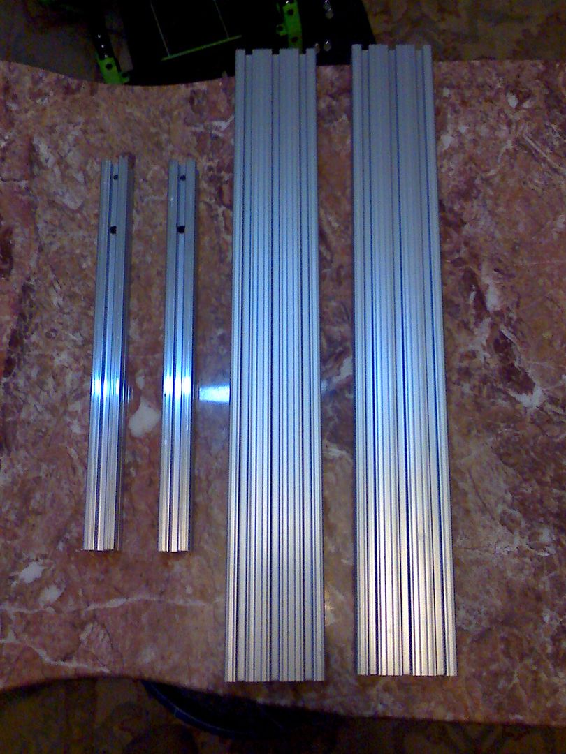 I picked up the last of the 24 x 16 inch panels last week that are made out of a product called Athlon. I don't know what these panels had been made for but they are coming in handy. I should have bought a bunch at the time. Here is a picture of the sheet with two of the 1x3x22 inch #10 series T-Slot rails, The little 1x1x13.5 inch is in the back I will cut mount a sheet of Athlon to use as a sliding drawer later on. I wont need a slide. I will use the bottom slot for that purpose. I also found these boxes at the Dollar Store. These will be used to store the work tools ect. . 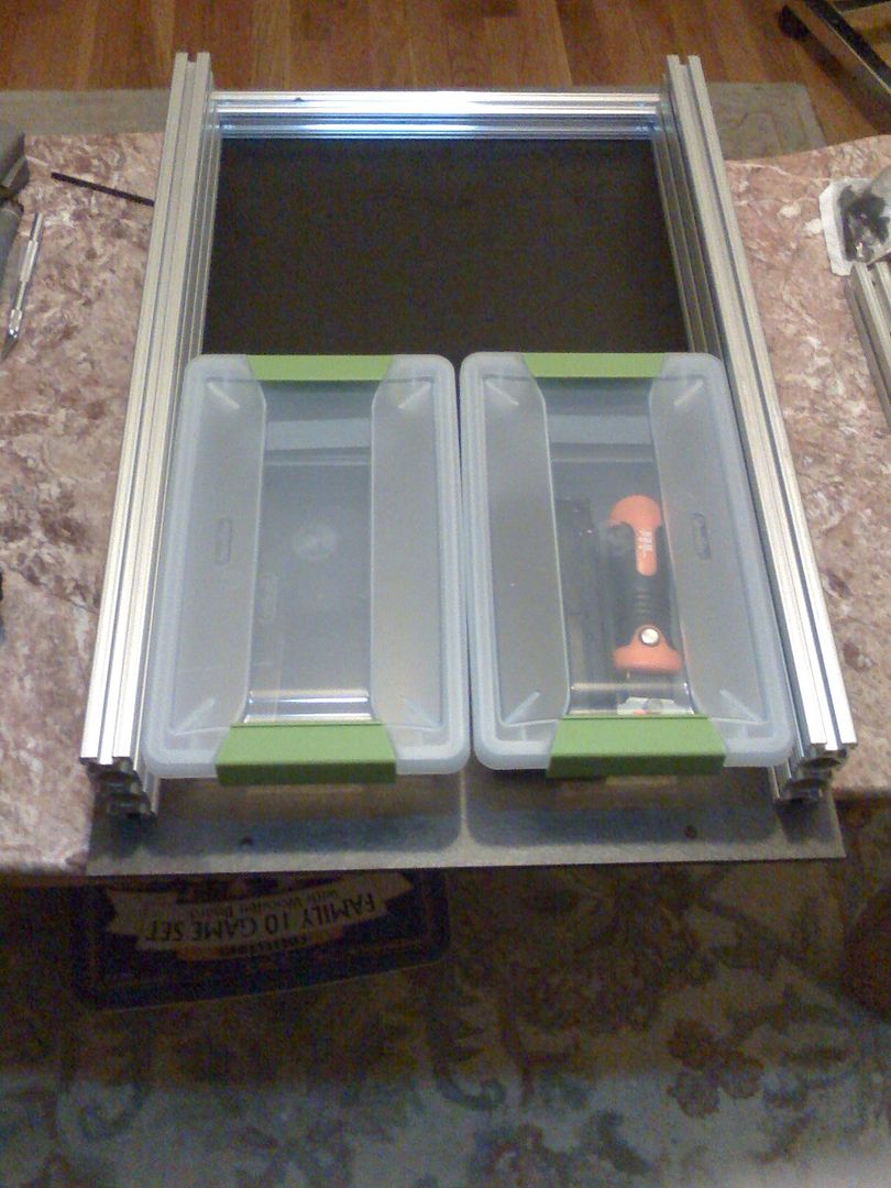 This is the underside with two sets of stick on feet from the Dollar Store. I may end up capping the screws or replacing them all together with FHSC on the bottom only. They are scratching the furniture. 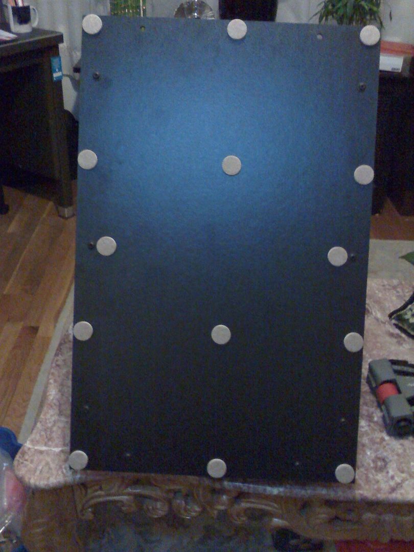 This is what it currently looks like with the base assembled for now. Later I will have to disassemble the top or bottom of the base for the electrical going in.for modifications inside. Since I will not be able to install the 12V power supply inside the printer because of the Y-axis being to large on this Mendy 1.5, then I have to have to place it inside the base. 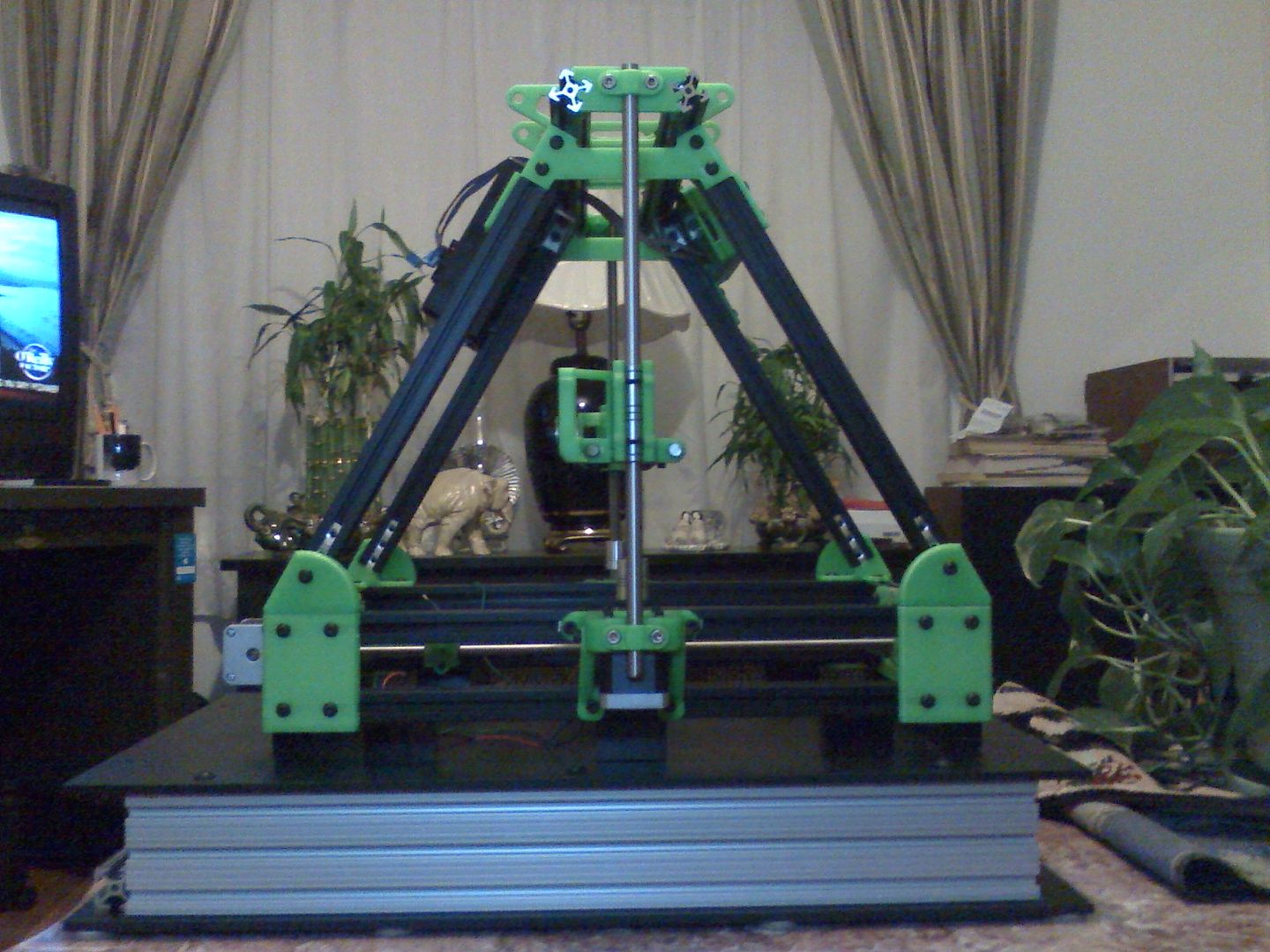 Front view of the base and the Mendy.  Rear view of the Mendy. I may not waste a perfectly good 1x1x13.5 inch rail($ 2.79 each) there.  Then I found these parts that I also ordered in the shipping box.  What the hell are those for?  |
|
|
|
[#3]
Get a 3d printer to print 3d printers... Will be like raising rabbits.
Posted Via AR15.Com Mobile |
|
|
|
[#4]
i got z and x working.. just have to build y, and the extruder..
|
|
|
|
[#5]
I didnt build the extruder yet. I have to finish the X.
Too busy with other repairs around the house. Just fixed the weed whacker and found a solution to a problem. Ever have the line inside the spool fuse together? Ever have the spool jam. Well the Toro electric trimmer that I have has been doing all that and then some. The line heats up from spinning and does the above crap. Dawned on me today that I really need some sort of lubricant that would prevent these problem without gumming up. Well remember the lubricant with PTFE ( Tri-Flow Superior Lubricant) that I'm using for the linear bearings. Well it also comes in a spray can. I sprayed all the interior of the spool housing (inside and out) and doused the spool and line with the Tri-Flow. It worked great. No jamming. No fusing. No sticking line. Now I have to clean and do the same to the other weed whacker. |
|
|
|
[#6]
For those building a RepRap Prusa MendelRepRap Prusa Mendel Iteration 2 Assembly Intro |
|
|
|
[#7]
The makerbot Y axis car assembly is quite different from the one shown in the trinity or utilibot build docs.
The one in the trinity manual is a single piece with a flat t-slotted surface on top and the whole thing slides onto the Y rail. The makerbot instead comes with 4 rail car "feet" and a plate that looks like it bolts to the feet. And then the insulator plate bolts to that. But the insulator plate isn't pre drilled. Dammit. Now I have to change out of my pajama bottoms. |
|
|
|
[#8]
Quoted: The makerbot Y axis car assembly is quite different from the one shown in the trinity or utilibot build docs. The one in the trinity manual is a single piece with a flat t-slotted surface on top and the whole thing slides onto the Y rail. The makerbot instead comes with 4 rail car "feet" and a plate that looks like it bolts to the feet. And then the insulator plate bolts to that. But the insulator plate isn't pre drilled. Dammit. Now I have to change out of my pajama bottoms.  Now you know how I feel. |
|
|
|
[#9]
Hm...
The makerworks Y-kit comes with: An aluminum heat spreader A flexible heater circuit that you stick to the aluminum heat spreader And a piece of glass you lay on top of the whole thing. And then you lay the whole heated glass bed assembly directly onto this y-shaped Y-azis plate that has back angled adjustable brackets that you snug up against the glass to hold it down. But the trinity instructions has a plastic insulator on bottom, plastic standoffs, and a red heated bed plate sandwiched between them (presumably not touching the insulator). I think I understand how the makerworks kit is supposed to go together but... I also have a red PCB heater stiff plate similar to the one shown in the trinity instructions. I believe it came with my ramps kit. It's smaller than the flexible kapton heater circuit that came with the makerworks Y axis kit, tho. Should I go with the makerworks heater or the red PCB heater plate? eta: Ugh, I think some of my plastic parts are unusable. I found one piece missing holes outright, I think. I might have to depend on the kindness of strangers to print a part or two for me to get me up and running. Standby... |
|
|
|
[#10]
Quoted:
Hm... The makerworks Y-kit comes with: An aluminum heat spreader A flexible heater circuit that you stick to the aluminum heat spreader And a piece of glass you lay on top of the whole thing. And then you lay the whole heated glass bed assembly directly onto this y-shaped Y-azis plate that has back angled adjustable brackets that you snug up against the glass to hold it down. But the trinity instructions has a plastic insulator on bottom, plastic standoffs, and a red heated bed plate sandwiched between them (presumably not touching the insulator). I think I understand how the makerworks kit is supposed to go together but... I also have a red PCB heater stiff plate similar to the one shown in the trinity instructions. I believe it came with my ramps kit. It's smaller than the flexible kapton heater circuit that came with the makerworks Y axis kit, tho. Should I go with the makerworks heater or the red PCB heater plate? eta: Ugh, I think some of my plastic parts are unusable. I found one piece missing holes outright, I think. I might have to depend on the kindness of strangers to print a part or two for me to get me up and running. Standby... the kapton heater needs 24 volts.. I know Im looking at it too.. so to do the other y axis, you need a 24 PSU then a 24 to 12 volt converter. remove D2 diode and run a SSR for the heater bed. im thinking in teh long run it would of been cheaper to get a full kit, and not piece meal it like I did.. |
|
|
|
[#11]
Having problems with the hob bolt.
 If I turn the bolt around as the wade extruder this as is on EBAY. I ended up with too many washers on the gear side and the small gear on the motor has to come out too far. There is a guy on Ebay that ill make your hob bolt to your dimension. RG92dL!~~60_57.JPG) Some of the hobbed bolts are cut too deep from the photos on ebay. It might be a problem with smaller filaments.  This one would have fit a lot better.  But. I like this ideas. It is adjustable at both ends for centering. Less washers.  |
|
|
|
[#12]
Make one?
|
|
|
|
[#13]
the kapton heater needs 24 volts.. I know Im looking at it too.. so to do the other y axis, you need a 24 PSU then a 24 to 12 volt converter. remove D2 diode and run a SSR for the heater bed. im thinking in teh long run it would of been cheaper to get a full kit, and not piece meal it like I did.. I've got a 12V PSU right now... Could I not just get a 24V wall wart dedicated to powering the heated bed? How many amps does the bed heater draw? Is the bed temperature controlled by the Ramps controller board via on/off switching done by the SSR? Looks like it might be, judging from the circuit diagram on page 1. eta: Hm, the makerworks website description says the kapton heater expresses 200W, so I'm presuming that makes it an 8.33_ amp draw at 24V. So 10 amp rated 24V supply dedicated to the heated bed. |
|
|
|
[#14]
Hm. Not sure I feel comfortable trying to desolder D2 from the ramps board. What's it do, anyways? There's some documentation on the wiki about D1, but very little about D2... other than telling people building their own Ramps boards to "definitely solder it in."
The Kapton heater has two sets of wires. One small and black, with a connector termination. This is obviously meant for one of the thermistor circuit pins on the ramps board. The other set of wires is larger and red. On the circuit diagram, this would seem to go to the terminal D8. HOWEVER, my board will be powered by a 12V power supply and the Kapton heater is 24V. So I am guessing the solid state relay solution is: D8 on the Ramps board get's wired to 12VDC coil inputs on the SSR and the red power wires on the kapton heater get attached to the output of the SSR and the 24VDC power supply get's wired to the input of the SSR? eta: This presumes that the whole thing operates like I'm GUESSING it works. IE, the thermistor circuit is only an input used by the arduino to tell when to open or close the circuit to D8. Damn I wish there was more in-depth documentation on this stuff. |
|
|
|
[#15]
Quoted: the kapton heater needs 24 volts.. I know Im looking at it too.. so to do the other y axis, you need a 24 PSU then a 24 to 12 volt converter. remove D2 diode and run a SSR for the heater bed. im thinking in teh long run it would of been cheaper to get a full kit, and not piece meal it like I did.. I've got a 12V PSU right now... Could I not just get a 24V wall wart dedicated to powering the heated bed? How many amps does the bed heater draw? Is the bed temperature controlled by the Ramps controller board via on/off switching done by the SSR? Looks like it might be, judging from the circuit diagram on page 1. eta: Hm, the makerworks website description says the kapton heater expresses 200W, so I'm presuming that makes it an 8.33_ amp draw at 24V. So 10 amp rated 24V supply dedicated to the heated bed. Bed is plugged into the Ramp at D8. The Bed thermister is plugged int T1 position on Ramp Bd.  More info here http://reprap.org/wiki/RAMPS_1.4 |
|
|
|
[#16]
Thanks, I've been referring to those.
My bed heater is 24V and my PS is 12V, tho. |
|
|
|
[#17]
 Fucken messed up kit. The kit was supposed to have 6-M3-.5x40mm SHCS it only had two. These were supposed to be used on mounting the lower aluminum plate to the Y-axis. Found out that the six screws in the compartment in the box were actually 6-M3-.5x30mm SHCS. Then I checked the compartment for the 2-M3-.5x30mm SHCS were actually 2-M3-.5x40mm. These are for the Wades extruder. The 2-M3-.5x30mm SHCS were just a little to short. So I used the 2-M3-.5x40mm for the extruder along with spacers as used on the Mendelmazx 1.5+. So. The 2-M3-.5x30mm SHCS are useless to this kit, and now I am short 6-M3-.5x40mm SHCS Yep. MSC is getting another sale. These are not cheap. $28 with shipping for 50 pcs. $49 for 100 pcs with shipping. Be careful when buying a kit. If you buy on Ebay. Do not give a Feedback until you build the kit. The hardware on my kit did not match the parts that were made. The seller played games and only replaced the first set of missing screws. |
|
|
|
[#18]
Yeah, I'm not particularly thrilled with the quality of some of this stuff. A few of the components on my ramps board were bent because the box was too small. Hopefully they weren't broken. Meh.
Some of the plastic parts are atrocious, tho. This is what I'm talking about doing for my bed heater: 
Second, dedicated 24V power supply to run the 24V kapton heater bed. Operating power supplied through the relay. Relay "coil" controlled by D8 on the Ramps board. Why will or won't this work? |
|
|
|
[#19]
Here's an illuminating discussion on how to run a Ramps board on 24V instead of 12V.
http://forums.reprap.org/read.php?219,196602,196602 Looks like a real pain in the ass. |
|
|
|
[#20]
Electrical gurus...
http://www.ebay.com/itm/Solid-State-Relay-SSR-40DA-40-AMP-3-32VDC-Output-24-380V-AC-SSR-40A-Module-/321123577566?pt=LH_DefaultDomain_0&hash=item4ac474eede Could this 24VAC to 380VAC 40 amp-rated relay handle 8.33 amps at 24VDC without melting? Yes, I realize this is kind of a dumb question, but just bear with me.
Finding actual DC coil and DC in/out relays for anything less than 60 or 70 bucks is proving difficult. |
|
|
|
[#21]
Quoted:
Having problems with the hob bolt. If I turn the bolt around as the wade extruder this as is on EBAY. I ended up with too many washers on the gear side and the small gear on the motor has to come out too far. There is a guy on Ebay that ill make your hob bolt to your dimension. http://i.ebayimg.com/t/Hobbed-Bolt-M8-for-Gregs-Reloaded-Tilt-Extruder-Herringbone-Prusa-Mendel-Reprap-/00/s/MTIwMFgxNjAw/$T2eC16NHJGkE9no8gGLyBQ)RG92dL!~~60_57.JPG I have mine this way, and would think it is preferred. My small gear is flush with the end of the shaft of the motor, which I consider acceptable. I would get a hobbed bolt with the cuts at the correct position for your setup. Using the head of the bold in the gear means there is no way it can come loose. The highest stress part is the head being twisted continually by the gears/motor.. Using a nut on that end could eventually move on the threads and thus move the hobed portion and cause jamming. |
|
|
|
[#22]
Quoted:
Thanks, I've been referring to those. My bed heater is 24V and my PS is 12V, tho. Are you using an ATX power supply? If so, just hook the -12 and +12 up to get 24v using a 24v automotive relay connected to the ramps heated bet output to control the bed. That will give you a 24v potential difference and you should be good to go. Something like this relay http://www.carid.com/universal-off-road-lights/kc-hilites-off-road-lights-1634975.html?CAWELAID=1723085933&cagpspn=pla&gclid=CKXdl5O0o7cCFYqY4AodeGUAoA should work. If it isn't an ATX supply, and doesn't have a -12v connection you might be out of luck and have to purchase a 24v supply. The 11A bed is independent from the 5A which powers the rest. So you can have a 24V bed and keep the 5A input at 12V and not need to remove the diode. But you will need a second supply or one capable of both 12v and 24v. You have to use the relay for the ATX supply since it doesn't have the ability to make a 24v connection to the 11A common ground terminal on the ramps. This thread has more information. |
|
|
|
[#23]
Quoted:
Quoted:
Thanks, I've been referring to those. My bed heater is 24V and my PS is 12V, tho. Are you using an ATX power supply? If so, just hook the -12 and +12 up to get 24v using a 24v automotive relay connected to the ramps heated bet output to control the bed. That will give you a 24v potential difference and you should be good to go. Something like this relay http://www.carid.com/universal-off-road-lights/kc-hilites-off-road-lights-1634975.html?CAWELAID=1723085933&cagpspn=pla&gclid=CKXdl5O0o7cCFYqY4AodeGUAoA should work. If it isn't an ATX supply, and doesn't have a -12v connection you might be out of luck and have to purchase a 24v supply. The 11A bed is independent from the 5A which powers the rest. So you can have a 24V bed and keep the 5A input at 12V and not need to remove the diode. But you will need a second supply or one capable of both 12v and 24v. You have to use the relay for the ATX supply since it doesn't have the ability to make a 24v connection to the 11A common ground terminal on the ramps. This thread has more information. My power supply is a Model LIHUA-360W 12V 30A total capacity. Three posts on the right for ground, neutral, and line. Three in the middle for -V. Three on the left for +V (adjustable?) I'm kind of thinking it's just a single 12V power source. I do have an old computer power supply I could probably use, tho. So to series wire a 24V circuit from two 12V circuits, I'd connect the positive wire from the first pair to the negative wire from the second pair and the remaining two wires would become the new and improved 24V pair, correct? At least, that's how it looks like on my old army truck...
Thanks, the help is much appreciated. |
|
|
|
[#24]
No, not quite like a battery with the PSU. You'll just use the -12v in place of ground to get 24v. You can see it in action with a multimeter. Just connect the black(com/negative) to the -12v and the red(positive) to the +12v and you'll show 24v. That's the current that would go through the relay to the bed. Then use the 12v coils on the 24v relay to the ramps board to trigger the relay.
You will want to confirm the max draw in amps of the 24v heated bed, and make sure your power supply is capable of handling that on the -12v lead. It should have a chart on the power supply or documentation/website. Sometimes supplies will have weak -12v leads. |
|
|
|
[#25]
Yeah, the -12V on the spare ATX psu I was able to find is rated 0.6A
Dang. Oh well, there's inexpensive 24V PSUs available on ebay, too... |
|
|
|
[#26]
So here is how I have it assembled right now.
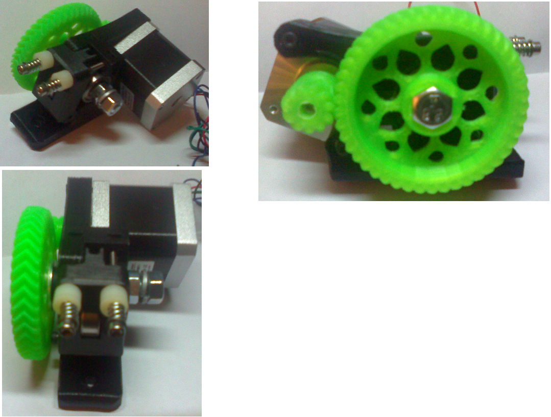 Having a problem with the two bearings for the Hob bolt. They are playing inside the holes. Hole is too big as the fall out on their own. Just read that other people are having the same problem. This is causing noise and vibration. Also the filament is not feeding properly. I will take the extruder apart and either shim or hot glue the bearings in. What would be better is the thick red loctite. Next I should pick up some 5/16 spring washer(s) to place on the back side of the extruder between the large gear and the first washer from the bearing. This will allow the hobbed bolt to move in and out slightly to stay in line with the small drive gear. Basically the large gear will float along with the smaller gear cutting down the noise and preventing any binding between the two. The play should be about .010 to .015 inch max. I'll have to get my dial indicators set up and try for .005 inch. I may have to place a second Spring washer on the front side to use as a self centering tensioner on the bolt. On thingiverse some guy made a mold out of ABS, added a release agent and used the extruder to inject the the mold with PLA since it melts at a lower temperature. Actually the mold should be made out of a higher temperature nylon so it can be use on both ABS and PLA. http://www.thingiverse.com/thing:82666 It can be a bit messy. The extruder has to be set at a higher speed to fill the mold. Fro a video that I watched yesterday on a Printer being set up. It was real fast and messy. |
|
|
|
[#27]
I have potted bearings like that in my dillon1200B trimmer with devcon steel putty and it worked great.
I used regular old johnson's paste wax as a release agent. For this application? Cheap automotive store epoxy should do the trick. |
|
|
|
[#28]
BTW.
These came in yesterday  2X SBR12-600mm 12MM FULLY SUPPORTED LINEAR RAIL SHAFT ROD + 4 SBR12UU BlockThey are 23 5/8 long. I'm going to have to remove a 1/8 inch on them. Also have to buy two support rails. |
|
|
|
[#29]
Went ahead and got a 24V power supply just for the bed. I'm going to need a dedicated power strip for all these power supplies!
|
|
|
|
[#30]
Where did you get your hobbed bolt?
I got to the extruder assembly portion of the trinity manual... and I haz no hobbed bolt. Actually, whose extruder hardware kit did you get? My extruder main groovemount piece is practically unusable. All of the holes on it need to be drilled out. One of the bearing seats is completely covered by an unecessary layer of plastic. I think I might just order an extruder kit, but damn... seems like there's alot of people making VERY shitty parts out there. |
|
|
|
[#31]
Quoted:
Where did you get your hobbed bolt? I got to the extruder assembly portion of the trinity manual... and I haz no hobbed bolt. Actually, whose extruder hardware kit did you get? My extruder main groovemount piece is practically unusable. All of the holes on it need to be drilled out. One of the bearing seats is completely covered by an unecessary layer of plastic. I think I might just order an extruder kit, but damn... seems like there's alot of people making VERY shitty parts out there. pop the bearing in and then drill the hole for the hobbed bolt. the slotted holes have a layer of loose plastic you have to cut out. I spent a full day cleaning up the kit I have.. very crappy for the price I paid.. this is teh bolt I used.. http://airwolf3d.com/store/products/concentric-reprap-mendel-prusa-hobbed-bolt-m8-by-airwolf-3d/ |
|
|
|
[#32]
How satisfied are you with the concentricity of the airwolf bolt?
I can imagine a situation where if your bolt or the groove was oblong a tendency for the machine to extrude too much or not enough plastic depending on the position of the rotation. |
|
|
|
[#33]
Quoted:
How satisfied are you with the concentricity of the airwolf bolt? I can imagine a situation where if your bolt or the groove was oblong a tendency for the machine to extrude too much or not enough plastic depending on the position of the rotation. very concentric. LOL its one of the best looking parts ive got yet. well besides the rails from misumi |
|
|
|
[#34]
Anyone here try PET instead of Kapton tape for glass film?
|
|
|
|
[#35]
Quoted:
So here is how I have it assembled right now. http://i2.photobucket.com/albums/y22/TractorDre/AR15/Mrndelmax%201%205/ExtruderAssyB_zpsa9dc292e.png Having a problem with the two bearings for the Hob bolt. They are playing inside the holes. Hole is too big as the fall out on their own. Just read that other people are having the same problem. This is causing noise and vibration. Also the filament is not feeding properly. I will take the extruder apart and either shim or hot glue the bearings in. What would be better is the thick red loctite. Next I should pick up some 5/16 spring washer(s) to place on the back side of the extruder between the large gear and the first washer from the bearing. This will allow the hobbed bolt to move in and out slightly to stay in line with the small drive gear. Basically the large gear will float along with the smaller gear cutting down the noise and preventing any binding between the two. The play should be about .010 to .015 inch max. I'll have to get my dial indicators set up and try for .005 inch. I may have to place a second Spring washer on the front side to use as a self centering tensioner on the bolt. On thingiverse some guy made a mold out of ABS, added a release agent and used the extruder to inject the the mold with PLA since it melts at a lower temperature. Actually the mold should be made out of a higher temperature nylon so it can be use on both ABS and PLA. http://www.thingiverse.com/thing:82666 It can be a bit messy. The extruder has to be set at a higher speed to fill the mold. Fro a video that I watched yesterday on a Printer being set up. It was real fast and messy. Where did you find those babby springs for the extruder bolts? I'm not having any luck. |
|
|
|
[#36]
Quoted: Here on EBAYWhere did you get your hobbed bolt? I got to the extruder assembly portion of the trinity manual... and I haz no hobbed bolt. Actually, whose extruder hardware kit did you get? My extruder main groovemount piece is practically unusable. All of the holes on it need to be drilled out. One of the bearing seats is completely covered by an unecessary layer of plastic. I think I might just order an extruder kit, but damn... seems like there's alot of people making VERY shitty parts out there. Just choose which one you need. http://www.ebay.com/sch/i.html?_trksid=p4712.m570.l1313.TR0.TRC0&_nkw=hobbed+bolt&_sacat=0&_from=R40 |
|
|
|
[#37]
oops double tap Well why waste the space. Found a bag of 25- 8mm spring washers for about $6 with free shipping for the wades extruder. I could not find any spring washers locally so I ordered from ebay. Also got more screws from MSC today. Man those guys are fast. It should be at $ 14 for Two Day(got in one day) shipping. One time they had it locally. They shipped in the morning and I got it in the afternoon. Well that saved me taking time of from work and driving to get it. I took 4 hours off and drove to KL jack to buy my hardware. That turned out to be very costly. They only had half of the screws, and paid for $12 shipping on the screws they didnt have and they shipped it ground. Taking 4 hours off and burning gas to get a partial order cost me an additional $75. Cheaper to pay MSC and getting the order right, cheaper shipping, and on time. |
|
|
|
[#38]
I went ahead and ordered the airwolf one on F_M's recommendation. I'm a bit gunshy of buying some of these parts that need to be precise/concentric/square from a stranger on ebay.
Sutherlands had some "handyman springs" package of 6 part number "SP-9701" which I think will work for the WG Reloaded extruder springs. They're too long, but it's easy enough to trim them. $2.xx for the pack. |
|
|
|
[#39]
Quoted: I went ahead and ordered the airwolf one on F_M's recommendation. I'm a bit gunshy of buying some of these parts that need to be precise/concentric/square from a stranger on ebay. Sutherlands had some "handyman springs" package of 6 part number "SP-9701" which I think will work for the WG Reloaded extruder springs. They're too long, but it's easy enough to trim them. $2.xx for the pack. Cant blame you. I got really screwed. Really I got Screwed. I can almost fill an 50 caliber Ammo box with all of my small boxes of screws that I have purchased to build this Mech assy. I'm in to $300 plus for screws and shipping. If this keeps going. I'll be able to build a fort of screw boxes. |
|
|
|
[#40]
OK. Airwolf 3D has better music.
|
|
|
|
[#41]
Really. #D printed Human Parts.
A liver. With all the drinking on this site we could make a killing. |
|
|
|
[#42]
Quoted:
Really. #D printed Human Parts. A liver. With all the drinking on this site we could make a killing. |
|
|
|
[#43]
Quoted: Quoted: Really. #D printed Human Parts. A liver. With all the drinking on this site we could make a killing. Welcome back from the land of the lost or missing members. Check this out. http://www.ebay.com/itm/Small-PCB-Drill-Press-Drilling-With-0-8mm-Drill-Diameter-28mm-Motor-Diameter-12V-/321018567060?pt=LH_DefaultDomain_0&hash=item4abe329994  This would make a nice option for the printer as a small CNC drill. At $3.76 each with free shipping. These things must cost pennies to make. I just ordered 1 and 3 spares. Once I receive them. I'll design and 3 D model of a holder for them. Could also design and then print out a miniature self contained drill press with a small X-Y slide table for one of the drills. |
|
|
|
[#44]
Not getting much done on the printer.
Time is getting eaten up researching mower parts for the gravely tractor, and the push mower drive wheel repairs. Also the black flies bit the crap out of me last weekend. They got into all sorts of places. I'm covered with hundreds of bites from head to toes. I'm glad its raining. |
|
|
|
[#45]
That's why I try not to breathe the outside air as much as possible.
Insects fuck in it. CNC printer related: Noticed a tiny bit of slop in the X-direction of the y-axis. Tension between the rail cars with a nut and screw takes it out. I might try to make a spring-loaded solution later, tho. Fine balance between precision and binding here, tho. |
|
|
|
[#46]
Quoted: That's why I try not to breathe the outside air as much as possible. Insects fuck in it. CNC printer related: Noticed a tiny bit of slop in the X-direction of the y-axis. Tension between the rail cars with a nut and screw takes it out. I might try to make a spring-loaded solution later, tho. Fine balance between precision and binding here, tho. Is that the 3d printer or the CNC. If CNC pics of the parts If it is the 3d printer with the updated Y rail system. Are the drylin blocks adjustable by turning a set srew on the side? |
|
|
|
[#47]
3D printer. No set screws to adjust it. But yeah, it's the ultibot/maker tool works style improved Y axis kit. Identical to this one.
http://www.ultibots.com/y-axis-upgrade-kit/ Upon reflection, I'm not sure it will have much effect on quality, in practice. The play is perpendicular to the direction of travel. And since that axis is completely unconnected from the X-axis, the momentum from the print head moving in X shouldn't affect it. I'm still going to see if I can mod these cars to take the play out. Looks pretty easy to fix, actually. |
|
|
|
[#48]
Got the airwolf hobbed bolt today. That was pretty fast. Looks pretty good to me.
|
|
|
|
[#49]
going to try and get my parts for the y axis cut out tonight. And build an insert for the extruder to hot end to fill the void between the two.
what is the wire thickness on the springs? and length? |
|
|
|
[#50]
Quoted: going to try and get my parts for the y axis cut out tonight. And build an insert for the extruder to hot end to fill the void between the two. what is the wire thickness on the springs? and length? The extruder spring wire is .040 inch ( 1.0mm) and the spring is .320 inch (8.2mm ) long |
|
|
 Win a FREE Membership!
Sign up for the ARFCOM weekly newsletter and be entered to win a free ARFCOM membership. One new winner* is announced every week!
You will receive an email every Friday morning featuring the latest chatter from the hottest topics, breaking news surrounding legislation, as well as exclusive deals only available to ARFCOM email subscribers.

AR15.COM is the world's largest firearm community and is a gathering place for firearm enthusiasts of all types.
From hunters and military members, to competition shooters and general firearm enthusiasts, we welcome anyone who values and respects the way of the firearm.

Subscribe to our monthly Newsletter to receive firearm news, product discounts from your favorite Industry Partners, and more.
Copyright © 1996-2024 AR15.COM LLC. All Rights Reserved.
Any use of this content without express written consent is prohibited.
AR15.Com reserves the right to overwrite or replace any affiliate, commercial, or monetizable links, posted by users, with our own.


