


Posted: 7/27/2013 1:20:09 PM EDT
|
As you might figure from my user name, I have a Ten-Tec Jupiter and an Icom IC-7200. The IC-7200 resides at my ham club's station along with a second 7200 to cover our HF needs. I also have an Icom IC-718 for Field Day and portable HF uses.
The IC-7200s, more recent IC-718s, and other Icom rigs come with their HM-36 microphone that differs from their earlier HM-36. The more recent microphones have "Made in China" on the back and do not have the audio quality of their earlier HM-36s. Hams being what they are, there are a number of modifications published for this mic. The one I chose is the K1RF mod which is posted as a pdf in the Files section of the IC-7200 Yahoo Group. (Disclaimer! This mod is ONLY for the "Made in China" mics and not for any other HM-36 mics.) This mod involves removal of two capacitors and two resistors, and installing two new resistors and one transistor. The transistor may be just about any small signal NPN type, such as 2N3904, 2N2222A, 2N4401 (all three of which are available at Radio Shack), and other similar transistors. The resistors required are 1 ea 1.5k ohm 1/8 or 1/4 watt and 1 ea 10k ohm 1/8 or 1/4 watt. You will also need some Desoldering Braid ("Solder Wick") and Rosin Flux, some small diameter (the smaller the better) 60-40 rosin core solder, and a 30-40w pencil iron. Avoid RoHS solder like the plague. If you have all your parts and other items ready, let's get started. Open the mic case by removing three Philllips screws. Unplug the mic element from the circuit board and set the front of the mic aside. 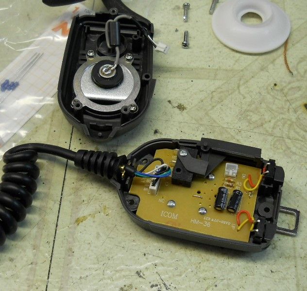
By removing four small screws the board may be removed from the back cover of the microphone. 
The parts required for this modification are one small signal NPN transistor, one 1.5k resistor, and one 10k resistor, as mentioned at the top of this post. 
2N3904 RS 276-2016 or other sources 2N4401 RS 276-2058 or other sources 2N2222A ditto (I've modded these mics with all three of these listed transistors.) |
You will need some desoldering braid (aka "Solder Wick").

You will also need some Rosin Flux. 
Dipping the end of the desoldering braid into the rosin flux will greatly aid in solder absorbtion. Lay the braid on top of the pad to be desoldered, then press the tip of your soldering iron (30-40 watt pencil iron) on the braid, let it heat a few seconds, remove iron and braid. Clip off the solder filled braid and repeat as needed until the lead is loose in the cleared hole. |
These are the parts to be removed. Two capacitors, labeled C1 and C2, and two resistors, labeled R1 and R3.

Removing the components. Note the desoldering braid has soaked up the solder and left the holes open. Then simply clip off the solder filled braid and repeat as needed. 
|
|
Here are the new parts installed. The 1.5k ohm resistor is soldered in place of capacitor C2. The 10k ohm resistor is soldered in place of resistor R3.
The transistor is soldered like this: The Emitter goes into the hole of R1 closest to the top edge of the board. The Base is next, in one of the holes formerly occupied by one of the leads of C1. The Collector goes in the remaining C1 hole closest to the bottom edge of the board. Note the orientation of the flat side of the transistor. IF YOU USE ANOTHER TRANSISTOR double check the lead assignments. They may be in another order. The flat may face the other way. Whatever the shape of the transistor, the Emitter, Base, and Collector must go as marked in the photos below. 

Finished board. 
Now reassemble the mic and enjoy its improved performance. |

|
Quoted:
I volunteer to be a beta tester.  You know how to get in touch. We can arrange that. 
But seriously, this is an easy mod. The most difficult part is desoldering the four parts. Using some rosin flux on the braid helps it wick up the melted solder and I was able to do this much easier once I added flux to the braid. Soldering the new parts back in is easy. The transistor legs neatly fall into the hole there on the board, just barely spreading them. The transistor does not really amplify, but rather, buffers the mic element so it is not loaded down by the rest of the mic circuit. The removal of caps and the new resistors make for a more flat frequency response, bringing up low frequencies, but more importantly, the high frequencies, too. The highs are important for clarity of speech. |
|
Thanks guys. I didn't invent this, and in fact, Steve K1RF didn't. He tweeked a mod by another ham, PY3SS, and altered the value of one resistor, using the 1.5k instead of, I think, 1k. On the Icom IC-7200 yahoo group both of these mods are in the Files sections.
I had done another mod on one of these mics, but this one is better. No drilling holes, no added wiring, or new boards, cutting traces, nothing like that. The new parts go back into existing holes, which I think is neat. The parts are easy to get, common Radio Shack or junk drawer parts. PY3SS used a BC547B transistor, and K1RF used a metal case 2N2222A. I've used four different transistors on these, and swapping mics around with an unmodified mic, all sound the same on the air I am told, and better than the unmodified mic. So, the transistor really is not critical. As you know, these transistors I listed are often substituted for each other in many circuits. The most difficult part is desoldering. The flux makes a lot of difference, and reduces the chance of overheating the pad and lifting the trace. I've done that before, and simply scraped the green coating off the same trace further over, bent the lead over and soldered. Just make sure you put Emitter, Base, and Collector in the correct holes as shown. |
Cool thread 
While you're at it, maybe replace the goofy mic hanger for a proper one.... ( this is my TS-480 mobile ) 
http://www.amazon.com/gp/product/B000X3D7C2/ref=oh_details_o03_s00_i00?ie=UTF8&psc=1 
, |

Join the Community
Your next conversation starts here.
Create your free account to join discussions, share your experience, save topics, and connect with the AR15.COM community.
- Join discussions
- Follow topics and replies
- Connect with fellow enthusiasts
Already a member? Sign in
Stay informed by subscribing to our Newsletter