


Armory Sponsor


Posted: 1/21/2017 12:29:21 AM EDT
Looking for a little help on baffle design on my next can. This will be a .223 6" can. I'll be using a DM 1.625" tube and DM baffles with SCE endcap. With the can being so short it is difficult to figure out the best baffle layout. I've attached a rough sketch of 2 different layouts I am considering. Any advice on which may be better is appreciated. I made these using measurements I found on this forum for the baffles so it may be just a tiny bit off but it should at least show the general idea. I end up with some odd ball lengths for first and last baffle spacing which will be cleaned up in the final design, but for now I just want to pick which baffle layout will be best and see if I need to make any other changes.

|

| You could take the top design, move the .304 space on the right into the blast chamber, and reduce spacers between baffles by 1/8". I think this would give you enough room to run most of the full size Griffin mounts. I just did quick mental math on that though, so get out your calculator and double check. The larger blast chamber should also reduce back pressure to some degree. |
|
Quoted:
You could take the top design, move the .304 space on the right into the blast chamber, and reduce spacers between baffles by 1/8". I think this would give you enough room to run most of the full size Griffin mounts. I just did quick mental math on that though, so get out your calculator and double check. The larger blast chamber should also reduce back pressure to some degree. I've thought about that but this can will mostly be used on one gun and I want to try to maximize sound suppression and first round pop given it's already small size. |
|
Honestly, I think they will perform almost equally. There really isn't enough difference between them to justify one or the other (for suppression). Back pressure, baffle life, and baffle spacing would be my top three concerns with either can. Between the two, I'd go with the top design. I don't believe your can is long enough to benefit from varying the baffles spacing.
Being the fact that this is being built on a Form1, I'd: 1. stretch-out the blast spacing -decrease back pressure -better for a non-adjustable gas gun and the shooter -coupled w/ baffle clip design, can increase efficiency -extend blast baffle lifespan -an eroded baffle face/bore opening can destabilize bullets and counter some cross-jetting 2. decrease baffle spacing -gas is going to expand so give it more chambers to do so in -more faces, using 60* cones, generally results in better performance 3. see if another baffle could be squished in there -more faces, using 60* cones, generally results in better performance 4. consider using equalization ports. -this style of design is proven to benefit from them |
|
Quoted:
Honestly, I think they will perform almost equally. There really isn't enough difference between them to justify one or the other (for suppression). Back pressure, baffle life, and baffle spacing would be my top three concerns with either can. Between the two, I'd go with the top design. I don't believe your can is long enough to benefit from varying the baffles spacing. Being the fact that this is being built on a Form1, I'd: 1. stretch-out the blast spacing -decrease back pressure -better for a non-adjustable gas gun and the shooter -coupled w/ baffle clip design, can increase efficiency -extend blast baffle lifespan -an eroded baffle face/bore opening can destabilize bullets and counter some cross-jetting 2. decrease baffle spacing -gas is going to expand so give it more chambers to do so in -more faces, using 60* cones, generally results in better performance 3. see if another baffle could be squished in there -more faces, using 60* cones, generally results in better performance 4. consider using equalization ports. -this style of design is proven to benefit from them Can you explain and equalization port? I haven't seen that term before, but I have been hiding under a rock for a few months. |
|
Quoted:
Can you explain and equalization port? I haven't seen that term before, but I have been hiding under a rock for a few months. Quoted:
Can you explain and equalization port? I haven't seen that term before, but I have been hiding under a rock for a few months. Equalization ports can be found in several, top-tier, commercial suppressor. Notice the holes near the outer edge of the baffles? The AAC M42K is famous for them. 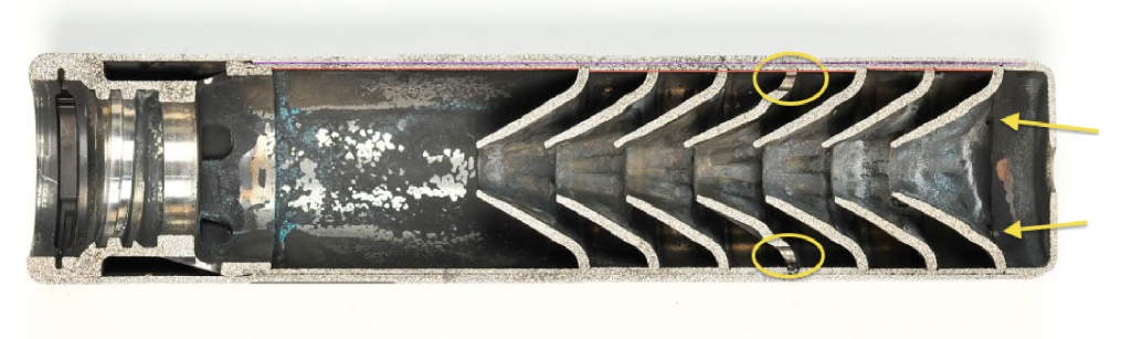
Surefire cans 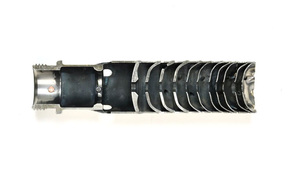
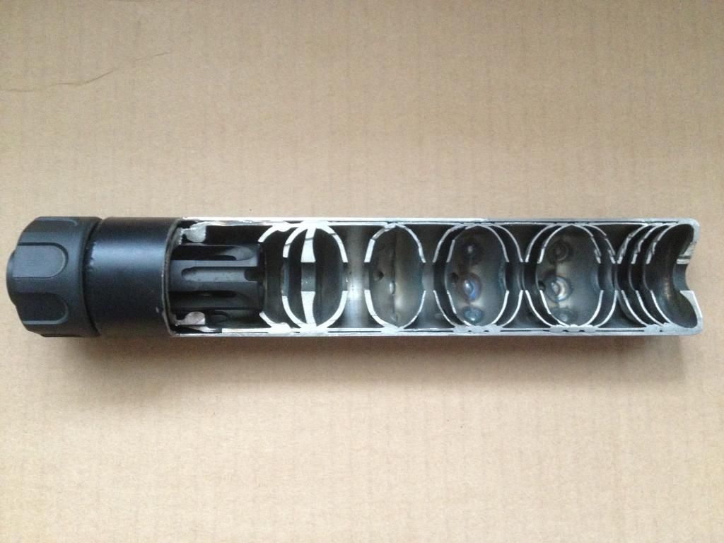
Sig's SRD line uses them 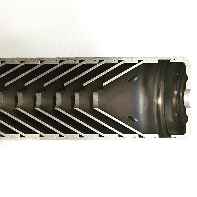
Envision a traditional 60*, cone can. The blast wave is sent through it and every chamber gets jammed with a portion of hot gases. Now put some holes in the outer edge of each baffle, or a deliberately chosen few, and watch the separate gas pulses move from one chamber to the next, canceling on another out. Like anything related to suppressor design, it can take some trial and error to reach maximum efficiency. They are also referred to as drain holes. For their use in draining water from a suppressor that has recently emerged from a river, or such, while being employed by a military unit. Quoted:He said he used CAD CAD simply stands for Computer-Aided Design/Drawing/Drafting. It does not imply any specific software. Just ask him what the name of the software he uses is |
|
Quoted:
Equalization ports can be found in several, top-tier, commercial suppressor. Notice the holes near the outer edge of the baffles? The AAC M42K is famous for them. http://i1300.photobucket.com/albums/ag97/Gunny-50/Diversen/Porting_zps5f25617f.png Surefire cans http://i205.photobucket.com/albums/bb176/Samson_104/sf2.jpg http://i1300.photobucket.com/albums/ag97/Gunny-50/Diversen/Cut%20Silencers/SF762-1_zpsa42241d7.jpg Sig's SRD line uses them http://i1300.photobucket.com/albums/ag97/Gunny-50/Diversen/Cut%20Silencers/9f4726c3-90ec-4274-b76f-dba1f24092c9_zpsk1rwuoak.jpg Envision a traditional 60*, cone can. The blast wave is sent through it and every chamber gets jammed with a portion of hot gases. Now put some holes in the outer edge of each baffle, or a deliberately chosen few, and watch the separate gas pulses move from one chamber to the next, canceling on another out. Like anything related to suppressor design, it can take some trial and error to reach maximum efficiency. They are also referred to as drain holes. For their use in draining water from a suppressor that has recently emerged from a river, or such, while being employed by a military unit. CAD simply stands for Computer-Aided Design/Drawing/Drafting. It does not imply any specific software. Just ask him what the name of the software he uses is Shows how much I know about this cad stuff haha. I asked again and he said specifically AutoCAD. |
|
Quoted:
Equalization ports can be found in several, top-tier, commercial suppressor. Notice the holes near the outer edge of the baffles? The AAC M42K is famous for them. http://i1300.photobucket.com/albums/ag97/Gunny-50/Diversen/Porting_zps5f25617f.png Surefire cans http://i205.photobucket.com/albums/bb176/Samson_104/sf2.jpg http://i1300.photobucket.com/albums/ag97/Gunny-50/Diversen/Cut%20Silencers/SF762-1_zpsa42241d7.jpg Sig's SRD line uses them http://i1300.photobucket.com/albums/ag97/Gunny-50/Diversen/Cut%20Silencers/9f4726c3-90ec-4274-b76f-dba1f24092c9_zpsk1rwuoak.jpg Envision a traditional 60*, cone can. The blast wave is sent through it and every chamber gets jammed with a portion of hot gases. Now put some holes in the outer edge of each baffle, or a deliberately chosen few, and watch the separate gas pulses move from one chamber to the next, canceling on another out. Like anything related to suppressor design, it can take some trial and error to reach maximum efficiency. They are also referred to as drain holes. For their use in draining water from a suppressor that has recently emerged from a river, or such, while being employed by a military unit. CAD simply stands for Computer-Aided Design/Drawing/Drafting. It does not imply any specific software. Just ask him what the name of the software he uses is Oh yeah. I know what those are. Just never had a name for them. 
|
|
Quoted:
I've thought about that but this can will mostly be used on one gun and I want to try to maximize sound suppression and first round pop given it's already small size. I just caught something in your reply. First round pop isn't something you will be able to hear on a can designed for supersonic rounds. The sound of the bullet is louder. |
Armory Sponsor