|
[#1]
I am no genius but the crossover is only or mostly to simply put the wire in the opposed position for layout purposes. A regular wind would have your wires both exiting at 6 o’clock. The crossover gets you in at 6 and out at 12. Edit to add the theoretical benefit of the crossover is to put distance between your just cleaned up line away from your “dirty line”.
Here are wrapping instructions for transformers for when you get to that point in your toroid usage. It is a great read for transformer type usage but not for choke usage like you need at the moment but do throw it in your saved radio reading files or bookmarks. http://www.gnarc.org/wp-content/uploads/The-End-Fed-Half-Wave-Antenna.pdf I am going to look for another site link, I think Palomar has a page on that if I can find it. I didn’t see what I was looking for on their site, I may be remembering a youtube video they had out. here is a link to a picture of a kit they sell for the ubiquitous IC7300 and it shows the common mode chokes they used. All 31 material ferrites iirc. https://palomar-engineers.com/wp-content/uploads/Palomar-Engineers-Icom-7300-RFI-Kit-Flyer.pdf 5-7 wraps through a toroid for the coax and power supply I noted. Here is one of their presentations and similar to what I recall watching. https://palomar-engineers.com/wp-content/uploads/ABCs-of-RFI-for-Hams-SPARC-10282021.pdf and since it was handy I popped the cover off my DXE max core 1:1 Balun. Inside are 2 cores that are most probably 240-31. Coax wrapped through center eleven times, 5, the crossover, and 5 more. There is a blue unmarked capacitor across the coax on the post side of the car as it is built to be a center feed choke for a dipole. I am guessing it is a high voltage 100pF rated cap. While it is a dipole box,....its main purpose is to choke common transmit power from radiating back on the coax to avoid making your dipole into a triplole. Not loose individual wire though, sorry. |
|
|
|
[#2]
Current baluns are generally superior to voltage baluns. Explanations are here.
If you are going from 50 Ohm characteristic impedance unbalanced transmission line (RG316 coax) to 300 or 450 Ohm characteristic impedance transmission line (e.g. DX Engineering window line), then you are going to want one of two solutions: a) non-resonant design, using an antenna tuner: 1:1 current balun b) resonant design, no antenna tuner: current balun with ratio as close to the impedance ratio as possible, i.e. 9:1 if the ratio is 450/50. 1:1 current balun construction example: 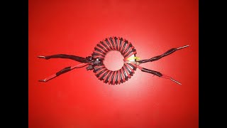 Current Balun 1:1 (Step by Step) |
|
|
|
[#3]
I built one on IIRC a 240 31 mix toroid using parallel wires. I used 14ga solid wire stripped out of some romex that still had insulation on it. I can't remember the reason why, but something about the thick plastic insulation makes it work out to being a 1.5:1 balun instead of a perfect 1:1.
Anyhow I should dig it out and see if it's 25 or 75 ohms. It might make it so I can use RG6. 
|
|
|
|
[#4]
Quoted: Current baluns are generally superior to voltage baluns. Explanations are here. If you are going from 50 Ohm characteristic impedance unbalanced transmission line (RG316 coax) to 300 or 450 Ohm characteristic impedance transmission line (e.g. DX Engineering window line), then you are going to want one of two solutions: a) non-resonant design, using an antenna tuner: 1:1 current balun b) resonant design, no antenna tuner: current balun with ratio as close to the impedance ratio as possible, i.e. 9:1 if the ratio is 450/50. 1:1 current balun construction example: I need to make one of those. I have seen arguments on that 2 pair winding and single pair winding for chokes. Didn’t see a consensus on which was better. I wonder if I can get the same effect on a 140 size for my QRP bag of or lower power. Hmmm. ETA I totally missed VOLTAGE balun being the novice trying to help out. Sorry. |
|
|
|
[#5]
Hi Mach,
The old 1:1 voltage baluns used a tri-filer, three wire winding. An older hand book should have something on them. IIRC small zip cord is too narrow for higher frequency HF, I think it has lots of loss but don't remember if it's the insulation material or the spacing. Why a voltage balanced balun? 73, Rob |
|
|
|
[#6]
Does this help?
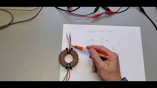 1:1 Common Mode Current Balun Explained |
|
|
|
[#7]
The most effective choke would be a binocular winding on two longer/thinner ferrites.
With RG-316 you could use somewhat smaller ferrites, Fair-Rite 2631625102 or 2631540002 for example. 3~4 turns is good. Such a choke is higher choking impedance, wider bandwidth, has no issues with impedance mismatches in the choke, and is more compact in size. |
|
|
|
[#8]
Great video! Current-mode baluns FTW! |
|
|
|
[#9]
Ok thanks for the help.
I guess I don’t want a voltage balun, I want a current balun. I am leaning toward a non-resonant antenna dipole fed with 300 ohm 20g window line. My primary bands will be 80 and 40 and 20 if I can get it. This is for QRP in the back country. Where I already have QRP endfeds and a 2 x multi-band Base loaded QRP verticals, one really QRP and the other not but more efficient. What can I say I like antennas and an efficient 80m antenna in the middle of nowhere is a bitch |
|
|
 Win a FREE Membership!
Sign up for the ARFCOM weekly newsletter and be entered to win a free ARFCOM membership. One new winner* is announced every week!
You will receive an email every Friday morning featuring the latest chatter from the hottest topics, breaking news surrounding legislation, as well as exclusive deals only available to ARFCOM email subscribers.

AR15.COM is the world's largest firearm community and is a gathering place for firearm enthusiasts of all types.
From hunters and military members, to competition shooters and general firearm enthusiasts, we welcome anyone who values and respects the way of the firearm.

Subscribe to our monthly Newsletter to receive firearm news, product discounts from your favorite Industry Partners, and more.
Copyright © 1996-2024 AR15.COM LLC. All Rights Reserved.
Any use of this content without express written consent is prohibited.
AR15.Com reserves the right to overwrite or replace any affiliate, commercial, or monetizable links, posted by users, with our own.