|
Posted: 4/26/2024 7:43:09 PM EDT
What's a good value for the resistor? How many Ohms and Watts should I use for discharging high voltage capacitors in a tube amp power supply?
I've bought a 3/8" thick fiberglass stake from Tractor Supply, and cut an 18" length from it. I ordered some 14 gauge silicone insulated wire that has a 30kV rating. The meter scale on my amp goes to 3.5kV, so 30kV insulation should be more than adequate. I just need to know what size resistor to use to bleed off the voltage from the capacitors at a reasonable rate (assuming the on-board bleeder resistors somehow quit working). For now, the highest voltage insulation I have is some 14 gauge 600V THHN. I made a stick with this, sans resistor, just to have something to use in case I can't wait for the proper insulated wire to show up. |
|
|
|
|
[#1]
Originally Posted By Jambalaya: I ordered some 14 gauge silicone insulated wire that has a 30kV rating. I don't have an answer - but a question. Would you have more info or a link to that silicone insulated HV wire that you ordered? |
|
|
|
|
[#2]
The wire doesn't need to be rated for high voltage since it will be held at ground potential. Also my Jesus stick's don't have resistors. Just test with a high voltage probe before Jesus sticking all high voltage components. I also attach ground jumpers to several locations on the high voltage circuit since there are no second chances.
|
|
|
|
TN, USA
|
[Last Edit: k8byp]
[#3]
MUST HAVE RESISTORS. NEVER short capacitors without a current limiting resistor!!
Filter caps , especially electrolytics, have a max current to not damage them. Look for the max current rating on similar type/ value caps. Safe side, find the total capacitance and assume a 10 second discharge. T= R x C. So R= T/ C Divide 3KV by the calculated R value to find the max current. Then fix whatevers wrong that the supply doesnt have bleeder resistors already. VERY IMPORTANT. DO NOT just quickly discharge HV caps, leave the discharge path connected for 10- 20 seconds. Capacitors at HV have a dangerous property called RESTRIKING. If only the surface of the dielectric is discharged, the caps will re- generate high voltage on the plates and it can be DEADLY. |
|
|
|
[#4]
The resistor value isn't that critical. 100K 1/2 watt would probably be fine.
Do you have to order these simple components? IM me your address and I will send you an assortment of common components from my stash. 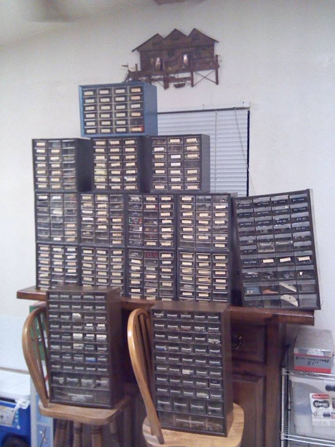 
|
|
|
|
|
[#5]
Originally Posted By targetworks: I don't have an answer - but a question. Would you have more info or a link to that silicone insulated HV wire that you ordered? I ordered it from Amazon. Search "high voltage silicone wire" and you will get several options ranging from 10kV to 40kV. This is the stuff I ordered. XJSXZC XJS Electric Copper Core Flexible Silicone Wire Cable Red (14AWG 30KV) 5M https://a.co/d/7vnmteE |
|
|
|
|
[#6]
Originally Posted By KB7DX: The resistor value isn't that critical. 100K 1/2 watt would probably be fine. Do you have to order these simple components? IM me your address and I will send you an assortment of common components from my stash. https://www.ar15.com/media/mediaFiles/108158/IMG_20180202_195450_130-2341578.jpg https://www.ar15.com/media/mediaFiles/108158/DSCN5824_JPG-2312624.jpg I do have a 1/8W and 1/4W resistor assortment. Perhaps I could parallel a couple of 200k 1/4 watt resistors and roll with that? I was thinking I'd need a big square ceramic resistor or something, but if I can get away with what I've already got, that's great. |
|
|
|
|
[#7]
You can't use just any old resistors, at least not safely. You need to use a resistor that is rated for the voltages it will be used for.
Mouser carries the Ohmite line of high voltages, metal oxide resistors ("MOX"). For instance, here is a resistor rated for 7.5KV and 1.5W: https://www.mouser.com/ProductDetail/Ohmite/MOX1125231006FE?qs=%2FhMMdHATMRWPguk0%2F9eR9w%3D%3D If you used this to discharge a capacitor charged to 7.5KV then, given that P = V^2/R, that works out to only 0.56W. That would be perfect for your application as long as it is below 7.5KV. And it's not too expensive at only $12 (plus shipping). And don't forget that the resistor needs to be encapsulated in some way that will keep you safe and keep any voltage from arcing across it. Here's a good article on a discharge stick build: https://www.worldwidedx.com/threads/building-a-capacitor-discharge-stick%E2%80%A6chicken-stick%E2%80%A6jesus-stick.263464/ |
|
|
|
|
[Last Edit: targetworks]
[#8]
Originally Posted By Jambalaya: I ordered it from Amazon. Search "high voltage silicone wire" and you will get several options ranging from 10kV to 40kV. This is the stuff I ordered. XJSXZC XJS Electric Copper Core Flexible Silicone Wire Cable Red (14AWG 30KV) 5M https://a.co/d/7vnmteE Originally Posted By Jambalaya: Originally Posted By targetworks: I don't have an answer - but a question. Would you have more info or a link to that silicone insulated HV wire that you ordered? I ordered it from Amazon. Search "high voltage silicone wire" and you will get several options ranging from 10kV to 40kV. This is the stuff I ordered. XJSXZC XJS Electric Copper Core Flexible Silicone Wire Cable Red (14AWG 30KV) 5M https://a.co/d/7vnmteE Thanks... It seems that there are some cables rated at tens of kV and others rated at 600V. My intended application is conveying the HV from a tube amplifier power supply to the amplifier. So I'd prefer to have a pair of cables with red and black jackets, but (at least so far) I've only found 'matching' cables with HV ratings in red and white - but I guess that will be good enough. (It does not inspire confidence in the claimed jacket ratings, however, when the vendor is one of those no-name all-capital-letter Chinese ones like XJSXZC that also sells other merchandise such as women's undergarments. So I will probably take a look at Mouser and see if they offer suitable alternatives.) While I'm at it, I might as well put together a discharge stick like the one that you're working on. Maybe I should get an HV meter probe too. (I may be overthinking things here - but when it comes to usage that could pose a threat to human life or safety, it's worth paying attention to details - for example, just because the insulation claims a certain HV rating, there are standards for such things that may be different for hand-held usage such as for test probes vs. applications not involving direct human contact - so I'm looking at resources such as IEC 61010-031 Safety requirements for electrical equipment for measurement, control and laboratory use – Part 031: Safety requirements for hand-held and hand-manipulated probe assemblies for electrical test and measurement.) ETA: This Pomona test lead wire comes in red (6733-2) and black (6733-0), and looks like it will do the job for me - each roll has 50 feet of wire, but I have at least two amplifiers for which I'm building power supplies, so I'm OK with it: https://www.pomonaelectronics.com/sites/default/files/d6733_6734_101.pdf https://www.digikey.com/en/products/detail/pomona-electronics/6733-2/737852 https://www.digikey.com/en/products/detail/pomona-electronics/6733-0/737851 |
|
|
|
|
[#9]
I have several Jesus stick's off AM transmitters I have disassembled, it you want one I'll grab it next time I'm at my storage unit and send it to you.
|
|
|
|
|
[#10]
Originally Posted By targetworks: Thanks... It seems that there are some cables rated at tens of kV and others rated at 600V. My intended application is conveying the HV from a tube amplifier power supply to the amplifier. So I'd prefer to have a pair of cables with red and black jackets, but (at least so far) I've only found 'matching' cables with HV ratings in red and white - but I guess that will be good enough. (It does not inspire confidence in the claimed jacket ratings, however, when the vendor is one of those no-name all-capital-letter Chinese ones like XJSXZC that also sells other merchandise such as women's undergarments. So I will probably take a look at Mouser and see if they offer suitable alternatives.) While I'm at it, I might as well put together a discharge stick like the one that you're working on. Maybe I should get an HV meter probe too. (I may be overthinking things here - but when it comes to usage that could pose a threat to human life or safety, it's worth paying attention to details - for example, just because the insulation claims a certain HV rating, there are standards for such things that may be different for hand-held usage such as for test probes vs. applications not involving direct human contact - so I'm looking at resources such as IEC 61010-031 Safety requirements for electrical equipment for measurement, control and laboratory use Part 031: Safety requirements for hand-held and hand-manipulated probe assemblies for electrical test and measurement.) ETA: This Pomona test lead wire comes in red (6733-2) and black (6733-0), and looks like it will do the job for me - each roll has 50 feet of wire, but I have at least two amplifiers for which I'm building power supplies, so I'm OK with it: https://www.pomonaelectronics.com/sites/default/files/d6733_6734_101.pdf https://www.digikey.com/en/products/detail/pomona-electronics/6733-2/737852 https://www.digikey.com/en/products/detail/pomona-electronics/6733-0/737851 Yeah I considered the source as well, but I'm not building it in such a fashion that it will pass through or near my hands like it would with test probes. The wire will leave the handle near the tip. And the other thing to consider is that I bought a $99 Chinese HV test probe that's going to have Chinese wire in it anyway.  I think the best practice is going to be making any test connections before applying power to the circuit, and then doing the old "keep one hand in your pocket" trick to avoid any path through your heart. I've taken a 120V jolt a couple of times that only hit one hand because the other was in my pocket. This was decades ago, and I don't care to experience anything like it again. |
|
|
|
|
[#11]
Originally Posted By aa777888-2: You can't use just any old resistors, at least not safely. You need to use a resistor that is rated for the voltages it will be used for. Mouser carries the Ohmite line of high voltages, metal oxide resistors ("MOX"). For instance, here is a resistor rated for 7.5KV and 1.5W: https://www.mouser.com/ProductDetail/Ohmite/MOX1125231006FE?qs=%2FhMMdHATMRWPguk0%2F9eR9w%3D%3D If you used this to discharge a capacitor charged to 7.5KV then, given that P = V^2/R, that works out to only 0.56W. That would be perfect for your application as long as it is below 7.5KV. And it's not too expensive at only $12 (plus shipping). And don't forget that the resistor needs to be encapsulated in some way that will keep you safe and keep any voltage from arcing across it. Here's a good article on a discharge stick build: https://www.worldwidedx.com/threads/building-a-capacitor-discharge-stick%E2%80%A6chicken-stick%E2%80%A6jesus-stick.263464/ Thanks for the links. That 100 meg Ohm resistor would take a long time to discharge though, right? I'm guessing you posted it as a recommendation for the wattage and voltage ratings, not the resistance rating? |
|
|
|
|
[#12]
Originally Posted By FlatlandBusa: I have several Jesus stick's off AM transmitters I have disassembled, it you want one I'll grab it next time I'm at my storage unit and send it to you. Sure, thanks! I'll probably still build one because I like building stuff, but It would be reassuring to have a real one. |
|
|
|
|
[#13]
Originally Posted By Jambalaya: Thanks for the links. That 100 meg Ohm resistor would take a long time to discharge though, right? I'm guessing you posted it as a recommendation for the wattage and voltage ratings, not the resistance rating? Yes, just an example. You can find an Ohmite MOX series high voltage resistor in wide variety of ratings. Obviously the higher power ratings will allow more current, therefore a smaller value of resistance can be used and discharge time will be faster. Looking again at the Mouser site, and using their search tools, the largest power rating in the MOX line is 20W, and this part here is 1MΩ and rated at 60KV: https://www.mouser.com/ProductDetail/Ohmite/MOX97021004FVE?qs=pL5SmcfXDY1w1zIinf3Izw%3D%3D If you don't mind paying $45 for that part it would be an ideal choice for any voltage up to 4.4KV (remember, P=V^2/R, you can do the math However, discharge times will still be lengthy for large capacitances. This can be improved by simply paralleling as many of these resistors as necessary to achieve a higher current and power rating. What is the largest capacitance you might have to discharge? |
|
|
|
|
[#14]
Originally Posted By aa777888-2: Yes, just an example. You can find an Ohmite MOX series high voltage resistor in wide variety of ratings. Obviously the higher power ratings will allow more current, therefore a smaller value of resistance can be used and discharge time will be faster. Looking again at the Mouser site, and using their search tools, the largest power rating in the MOX line is 20W, and this part here is 1M and rated at 60KV: https://www.mouser.com/ProductDetail/Ohmite/MOX97021004FVE?qs=pL5SmcfXDY1w1zIinf3Izw%3D%3D If you don't mind paying $45 for that part it would be an ideal choice for any voltage up to 4.4KV (remember, P=V^2/R, you can do the math However, discharge times will still be lengthy for large capacitances. This can be improved by simply paralleling as many of these resistors as necessary to achieve a higher current and power rating. What is the largest capacitance you might have to discharge? The capacitor bank in my amp is eight 330 microfarad caps, totalling 2640 microfarads. Good news is I got the amp to come on and the meters work. Watching the needle drop when it was turned off means the on-board bleeder resistors are probably working okay. |
|
|
|
|
[#15]
Originally Posted By Jambalaya: Yeah I considered the source as well, but I'm not building it in such a fashion that it will pass through or near my hands like it would with test probes. The wire will leave the handle near the tip. And the other thing to consider is that I bought a $99 Chinese HV test probe that's going to have Chinese wire in it anyway. I think the best practice is going to be making any test connections before applying power to the circuit, and then doing the old "keep one hand in your pocket" trick to avoid any path through your heart. I've taken a 120V jolt a couple of times that only hit one hand because the other was in my pocket. This was decades ago, and I don't care to experience anything like it again. Originally Posted By Jambalaya: Originally Posted By targetworks: Thanks... It seems that there are some cables rated at tens of kV and others rated at 600V. My intended application is conveying the HV from a tube amplifier power supply to the amplifier. So I'd prefer to have a pair of cables with red and black jackets, but (at least so far) I've only found 'matching' cables with HV ratings in red and white - but I guess that will be good enough. (It does not inspire confidence in the claimed jacket ratings, however, when the vendor is one of those no-name all-capital-letter Chinese ones like XJSXZC that also sells other merchandise such as women's undergarments. So I will probably take a look at Mouser and see if they offer suitable alternatives.) While I'm at it, I might as well put together a discharge stick like the one that you're working on. Maybe I should get an HV meter probe too. (I may be overthinking things here - but when it comes to usage that could pose a threat to human life or safety, it's worth paying attention to details - for example, just because the insulation claims a certain HV rating, there are standards for such things that may be different for hand-held usage such as for test probes vs. applications not involving direct human contact - so I'm looking at resources such as IEC 61010-031 Safety requirements for electrical equipment for measurement, control and laboratory use Part 031: Safety requirements for hand-held and hand-manipulated probe assemblies for electrical test and measurement.) ETA: This Pomona test lead wire comes in red (6733-2) and black (6733-0), and looks like it will do the job for me - each roll has 50 feet of wire, but I have at least two amplifiers for which I'm building power supplies, so I'm OK with it: https://www.pomonaelectronics.com/sites/default/files/d6733_6734_101.pdf https://www.digikey.com/en/products/detail/pomona-electronics/6733-2/737852 https://www.digikey.com/en/products/detail/pomona-electronics/6733-0/737851 Yeah I considered the source as well, but I'm not building it in such a fashion that it will pass through or near my hands like it would with test probes. The wire will leave the handle near the tip. And the other thing to consider is that I bought a $99 Chinese HV test probe that's going to have Chinese wire in it anyway. I think the best practice is going to be making any test connections before applying power to the circuit, and then doing the old "keep one hand in your pocket" trick to avoid any path through your heart. I've taken a 120V jolt a couple of times that only hit one hand because the other was in my pocket. This was decades ago, and I don't care to experience anything like it again. I took a 330 volt one once. When I was young and more foolish. I had to sit down for a bit and catch my breath. It was in the hand and out the forearm. Left hand was in the pocket. I knew I had a tiger by the tail on that one. |
|
|
|
|
[#16]
Originally Posted By K0UA: I took a 330 volt one once. When I was young and more foolish. I had to sit down for a bit and catch my breath. It was in the hand and out the forearm. Left hand was in the pocket. I knew I had a tiger by the tail on that one. Ouch! Was there any physical damage? The 120V didn't leave any wounds, but it was very unpleasant. |
|
|
|
|
[#17]
Those caps are probably in series so overall capacitance is about 41 mFd.
Caps in series reduce the capacitance but increase the voltage handling. Caps in parallel increase overall capacitance but the voltage capability stays the same. More from home if somd eone else doesn't chime in. |
|
|
|
|
[Last Edit: targetworks]
[#18]
Originally Posted By Jambalaya: The capacitor bank in my amp is eight 330 microfarad caps, totalling 2640 microfarads. Good news is I got the amp to come on and the meters work. Watching the needle drop when it was turned off means the on-board bleeder resistors are probably working okay. Originally Posted By Jambalaya: Originally Posted By aa777888-2: Yes, just an example. You can find an Ohmite MOX series high voltage resistor in wide variety of ratings. Obviously the higher power ratings will allow more current, therefore a smaller value of resistance can be used and discharge time will be faster. Looking again at the Mouser site, and using their search tools, the largest power rating in the MOX line is 20W, and this part here is 1M and rated at 60KV: https://www.mouser.com/ProductDetail/Ohmite/MOX97021004FVE?qs=pL5SmcfXDY1w1zIinf3Izw%3D%3D If you don't mind paying $45 for that part it would be an ideal choice for any voltage up to 4.4KV (remember, P=V^2/R, you can do the math However, discharge times will still be lengthy for large capacitances. This can be improved by simply paralleling as many of these resistors as necessary to achieve a higher current and power rating. What is the largest capacitance you might have to discharge? The capacitor bank in my amp is eight 330 microfarad caps, totalling 2640 microfarads. Good news is I got the amp to come on and the meters work. Watching the needle drop when it was turned off means the on-board bleeder resistors are probably working okay. Typically the capacitors in such a power supply are connected in series, in order to increase the working voltage rating (because each individual capacitor has a max working voltage of 450 volts, while the power supply may be putting out a couple thousand volts). So the total capacitance of the series-connected string of caps would be 1/8 of 330 uF rather than 8 X 330 uF. While the max voltage rating of the capacitor bank would be 8 X 450V. IIRC, if that is a Harbach board, then each capacitor has a 100K 5-watt resistor across it. So, those resistors are effectively in series, and their total resistance would be 800K. Also, IIRC, that HV supply is configured as a voltage doubler. I haven’t thought through the implications of that, but that may give you some parameters to consider when sizing your discharge stick. |
|
|
|
|
[#19]
Originally Posted By Jambalaya: Ouch! Was there any physical damage? The 120V didn't leave any wounds, but it was very unpleasant. Originally Posted By Jambalaya: Originally Posted By K0UA: I took a 330 volt one once. When I was young and more foolish. I had to sit down for a bit and catch my breath. It was in the hand and out the forearm. Left hand was in the pocket. I knew I had a tiger by the tail on that one. Ouch! Was there any physical damage? The 120V didn't leave any wounds, but it was very unpleasant. Not that I remember, but my arm was numb for a bit. Keep in mind this is nearly 50 years ago. It was a TV tuner tube type of course with the usual feed thru caps on the tuner for the 300 VDC B+ voltage for the plates of the tubes. I got onto one of those reaching in with one hand to change the tube. Stupid of course, but had got away with it many many times. It really knocked the stuffing out of me. As I remember that B+ supply was probably good for 250 to maybe as much a 500 milliamps. Easily enough to put your lights out if it went thru the heart. Of course it didn't, but it damn sure stunned me pretty good. I sat down in a cold sweat for some time. |
|
|
|
|
[#20]
Originally Posted By KB7DX: Those caps are probably in series so overall capacitance is about 41 mFd. Caps in series reduce the capacitance but increase the voltage handling. Caps in parallel increase overall capacitance but the voltage capability stays the same. More from home if somd eone else doesn't chime in. Lol, that's a big d'oh! moment there. You're right. I'll have to look at the schematic again but yeah, I think they are in series. |
|
|
|
|
[#21]
Originally Posted By targetworks: Typically the capacitors in such a power supply are connected in series, in order to increase the working voltage rating (because each individual capacitor has a max working voltage of 450 volts, while the power supply may be putting out a couple thousand volts). So the total capacitance of the series-connected string of caps would be 1/8 of 330 uF rather than 8 X 330 uF. While the max voltage rating of the capacitor bank would be 8 X 450V. IIRC, if that is a Harbach board, then each capacitor has a 100K 5-watt resistor across it. So, those resistors are effectively in series, and their total resistance would be 800K. Also, IIRC, that HV supply is configured as a voltage doubler. I haven't thought through the implications of that, but that may give you some parameters to consider when sizing your discharge stick. Thanks for your thoughts on this. It is a Harbach board. |
|
|
|
|
[#22]
I wish I had a dollar for every time I have done the 60Hz shuffle working on live circuits over the years. Sometimes you can't
just turn things off when troubleshooting. |
|
|
|
|
[#23]
Just buy a cattle prod or are those too wimpy?
|
|
|
|
|
[#24]
Originally Posted By Piratepast40: Just buy a cattle prod or are those too wimpy? In this case, I'm trying to neutralize a charge, not induce one. |
|
|
|
|
[Last Edit: stanprophet09]
[#25]
Originally Posted By lorazepam: I wish I had a dollar for every time I have done the 60Hz shuffle working on live circuits over the years. Sometimes you can't just turn things off when troubleshooting. As a good caution out there to everyone I was bit 3 times in the last 2 weeks. I was working on the 50v supply for my harris and it got me. Pretty weak but it reminds you. I was working on my TX/RX relay ground side and keyed the Bias and relays with no drive. Forgetting about inductive kick when the coil breaks down and it got me. Felt like taking a hit from an ignition coil. I was working on my 100amp HP 14v supply last night. I had upped the voltage on it a bit but found when keying my 2m brick amp it would cause the supply to shut down. So I decided to hook it to 120v instead of the 240. Opened up and then adjust Variable to back the voltage down and keep testing until I get the voltage to peak without shutting down on TX. Trying to stabilize it while turning the pot and finger bridged the case and a small aluminum heat sink. Not sure what is on the heat sink but it has a fiber cover you have to peel back. Found out the heatsink is hot! Worst part was I was wearing this shirt! |
|
|
|
|
[#26]
@targetworks
The wire arrived today. It's a lot fatter than I expected. Almost as thick as a pencil. I think the insulation should at least be adequate for 3kV considering it's rated for 30kV. I went ahead and ordered a 5W, 1 megohm resistor and a teflon tube to mount it, along with some banana plugs to mimic the design that @aa777888-2 linked above. I chose the 1 meg value because of the assessment that the total of the on-board bleeder resistors was 800k and that was the closest value. That said, it took quite a while for the HV meter needle to zero out after turning th amp off, so I may want to get a lower value resistor for a faster (but still cushy) discharge rate. And of course, verify with my HV probe before working on anything inside the amp. That said, opening the cabinet will ground the HV with the safety interlock anyway so if there was any remaining charge it is unlikely to survive being grounded that way. So like 3 layers of safety here. The reason for the HV wire is because if the alligator clip to the chassis comes off during use, then the wire will not be at ground potential. That and I'm okay with overbuilt. |
|
|
|
|
[#27]
Originally Posted By Jambalaya: I went ahead and ordered a 5W, 1 megohm resistor and a teflon tube to mount it, along with some banana plugs to mimic the design that @aa777888-2 linked above. I chose the 1 meg value because of the assessment that the total of the on-board bleeder resistors was 800k and that was the closest value. That said, it took quite a while for the HV meter needle to zero out after turning th amp off, so I may want to get a lower value resistor for a faster (but still cushy) discharge rate. And of course, verify with my HV probe before working on anything inside the amp. If this is too slow then simply parallel another identical resistor with the first one. That will increase the power rating to 10W, decrease the resistance to 500K, and halve the discharge time. Sanity check: does this all correlate with the discussion above about total series capacitance being 41.25μF and the bleeder resistance value being 800K? I.e. are you seeing it bleed from 3000V to about 1100V in about 33 seconds? |
|
|
|
|
[#28]
Originally Posted By aa777888-2: Sanity check: does this all correlate with the discussion above about total series capacitance being 41.25 F and the bleeder resistance value being 800K? I.e. are you seeing it bleed from 3000V to about 1100V in about 33 seconds? I didn't measure the time it took, but that seems about right. |
|
|
|
|
[Last Edit: Jambalaya]
[#29]
Okay so some supplies showed up today. I built one with the 1M resistor just to see how it would go together, and it looks like it worked out okay.
I have Teflon tubing with 3/8 ID and 1/2 OD. It's not super thick, but this build keeps the high voltage stuff isolated to the front 1/3 of the stick. This was 4.5" of Teflon tube some heat shrink, a banana plug, that 30kV 14 gauge wire I ordered, and a piece of a fiberglass electric fence stake. I used a couple of big zip ties to further secure the wire. It just so happens the fiberglass stake was a near perfect snug fit for the Teflon tube. |
|
|
|
|
[#30]
|
|
|
|
|
[#31]
nice.
|
|
|
|
|
[#32]
Nice job! So how long for a full discharge?
|
|
|
|
|
[#33]
Originally Posted By aa777888-2: Nice job! So how long for a full discharge? Well I haven't tested it yet because opening the amp triggers the safety interlock. I'd have to disable the interlock and even then, it would be working simultaneously with the amp's bleeder resistors. This is more for a safety tool to ensure there is no charge left should the on board resistors fail. |
|
|
|
|
[#34]
It's kind of important to know how it performs for real. You might want to do some more comprehensive testing. Otherwise you might leave it on for 60 seconds and then find out you've still got 400V on a cap the hard way
|
|
|
|
|
[Last Edit: Jambalaya]
[#35]
Originally Posted By aa777888-2: It's kind of important to know how it performs for real. You might want to do some more comprehensive testing. Otherwise you might leave it on for 60 seconds and then find out you've still got 400V on a cap the hard way Right. I do have another HV resistor on the way that's a 300K version in case 1 meg is too ponderously slow. I've got an HV probe I can use to test as well. I just need a day when the kids are out of the house and I can lock the cats in another room. With my luck a cat would jump at the amp and I'd instinctively grab it and complete the circuit through the cat.
|
|
|
|
|
[#36]
Originally Posted By Jambalaya: Right. I do have another HV resistor on the way that's a 300K version in case 1 meg is too ponderously slow. P = V^2/R. At the start of the first RC time constant that'll be 3000V squared and 9W for the 1M resistor, 30W for the 300K resistor Now you might get away with that because after the first time constant (41.25E-6 * 3E5) of 12 seconds the voltage will be down to 1890V at which point the power dissipation will be down to 12W, but why chance it? Simply parallel another 1M with the first one. Now you've got twice the discharge rate AND twice the power dissipation. If that's still not fast enough then simply add a third 1M, triple the power rating and achieve the equivalent of 333K. |
|
|
|
|
[Last Edit: Jambalaya]
[#37]
Originally Posted By aa777888-2: Ooh! Ouch! Don't just replace the 1M with the 300K. Remember that faster discharge rates mean more current which means more power dissipation in the resistor. P = V^2/R. At the start of the first RC time constant that'll be 3000V squared and 9W for the 1M resistor, 30W for the 300K resistor Now you might get away with that because after the first time constant (41.25E-6 * 3E5) of 12 seconds the voltage will be down to 1890V at which point the power dissipation will be down to 12W, but why chance it? Simply parallel another 1M with the first one. Now you've got twice the discharge rate AND twice the power dissipation. If that's still not fast enough then simply add a third 1M, triple the power rating and achieve the equivalent of 333K. Makes sense. But parallelling them will complicate construction. I'd need a bigger housing at the end of the stick. I could just line them up in a row, but that would necessitate running a thin wire alongside them, which negates any insulation value you get from the tubing to prevent arcing across the resistor (which is a long way to go for an arc, but still). The other way is side by side, which requires a much bigger housing. I could look for a different brand of resistor that has a higher wattage rating in a single component. |
|
|
|
 Win a FREE Membership!
Sign up for the ARFCOM weekly newsletter and be entered to win a free ARFCOM membership. One new winner* is announced every week!
You will receive an email every Friday morning featuring the latest chatter from the hottest topics, breaking news surrounding legislation, as well as exclusive deals only available to ARFCOM email subscribers.

AR15.COM is the world's largest firearm community and is a gathering place for firearm enthusiasts of all types.
From hunters and military members, to competition shooters and general firearm enthusiasts, we welcome anyone who values and respects the way of the firearm.

Subscribe to our monthly Newsletter to receive firearm news, product discounts from your favorite Industry Partners, and more.
Copyright © 1996-2024 AR15.COM LLC. All Rights Reserved.
Any use of this content without express written consent is prohibited.
AR15.Com reserves the right to overwrite or replace any affiliate, commercial, or monetizable links, posted by users, with our own.