TN, USA
|
Posted: 4/7/2024 5:55:06 PM EDT
What is bandwidth a function of?
I’ve heard the larger the wire the wider the bw. But I have an EFHW that has flat SWR below 1.5 the entire band from 7.000 - 7.300. And it’s a fairly small wire. Today I put up a half wave dipole made of wire that’s a good bit thicker. Spent hours tuning it (taking it down, adjusting wire length, putting it back up, over and over) and it was always about .150 wide. Meaning, if I tuned it to where the lowest swr was 7.000, 7.075 would be above 2.0. No balun or anything. Just directly connected to coax. Both antenna were in the same spot but not at same time. Just Used same cord in trees to tie each off. I know the 40m hamstick is even narrower and appears equally narrow as a vertical or with two of them as a dipole. |
|
|
|
[Last Edit: nikdfish]
[#1]
If you want to see how bandwidth can be broadened within a given antenna type, check out this archived thread. I did a 10m caged dipole. It ended up with a low SWR (<2) across the whole 10m band, 28.00 - 29.7
https://www.ar15.com/forums/outdoors/Just_for_fun___10m_cage_dipole/22-677644/ |
|
|
|
|
[#2]
the hamstick is narrower because it has an small diameter inductive coil inside the heatshrink |
|
|
|
|
[#3]
Originally Posted By taliv: What is bandwidth a function of? I’ve heard the larger the wire the wider the bw. But I have an EFHW that has flat SWR below 1.5 the entire band from 7.000 - 7.300. And it’s a fairly small wire. You will not see any significant differences between single wires in common gauges, i.e. no difference between using 14AWG vs 10AWG. The effective conductor diameter needs to be measured in the multiple inches range on HF frequencies to get significant SWR bandwidth improvement. As nikdfish suggests, the way you do this is to build a cage dipole or a ribbon dipole. Here is an excellent paper on ribbon and cage dipole antenna design: http://on5au.be/content/storart/8075bb1.pdf |
|
|
|
OH, USA
|
[#4]
Originally Posted By aa777888-2: I'd bet a beer that there's some resistance in the transformer. That's almost always how broadband, low VSWR performance is obtained from a single wire of "normal" size. Sonny Irons (of MaxCom infamy) approves this message. "The bottom line: MaxCom works." (To separate the gullible from their money better than anything else.) But there was no transformer in the device. Just a big 50 ohm resistor to which wires could be attached. |
|
|
|
[#5]
There is only one way for someone like Chameleon antennas getting 80-6m from their "tactical delta loop" antenna. It is through big losses in efficency, and a bunch of heat dumped into the 5:1 matching transformer. They claim you can get 80m with the matching unit and and a single 17' whip and a 3:1 tuner.
Look up Comet CHA, and you can see it is not a new concept. It's just 50db lower than a dipole would be due to the loss in efficiency. |
|
|
|
|
[#6]
Originally Posted By lorazepam: There is only one way for someone like Chameleon antennas getting 80-6m from their "tactical delta loop" antenna. It is through big losses in efficency, and a bunch of heat dumped into the 5:1 matching transformer. They claim you can get 80m with the matching unit and and a single 17' whip and a 3:1 tuner. Look up Comet CHA, and you can see it is not a new concept. It's just 50db lower than a dipole would be due to the loss in efficiency. Yet hundreds if not thousands will sing the praises of the CHA 250. Yes it works. It doesn't work very well, but like I say "everything works". And that includes dummy loads with a stick. All I can say is this: "Your going to have to get up pretty early in the morning Mr. Farmer* to beat a full size dipole up 1/2 of a wavelength" * apologies to Chevy Chase in the movie Funny Farm |
|
|
|
TN, USA
|
[#7]
Ok let’s say you have a 1/2 wave dipole 1/2 wave high. Let’s say 40m.
What would you expect the swr curve to look like? If you have such an antenna can you post a pic of the swr curve? |
|
|
|
[#8]
Originally Posted By taliv: Ok let’s say you have a 1/2 wave dipole 1/2 wave high. Let’s say 40m. What would you expect the swr curve to look like? If you have such an antenna can you post a pic of the swr curve? I would expect if the antenna was cut for 7.150 then a parabola with rising legs to perhaps just under 2.0 SWR. The low point would be under 1.5, maybe about 1.2 SWR Maybe. |
|
|
|
|
[Last Edit: Mach]
[#9]
Originally Posted By taliv: What is bandwidth a function of? I’ve heard the larger the wire the wider the bw. But I have an EFHW that has flat SWR below 1.5 the entire band from 7.000 - 7.300. And it’s a fairly small wire. Today I put up a half wave dipole made of wire that’s a good bit thicker. Spent hours tuning it (taking it down, adjusting wire length, putting it back up, over and over) and it was always about .150 wide. Meaning, if I tuned it to where the lowest swr was 7.000, 7.075 would be above 2.0. No balun or anything. Just directly connected to coax. Both antenna were in the same spot but not at same time. Just Used same cord in trees to tie each off. I know the 40m hamstick is even narrower and appears equally narrow as a vertical or with two of them as a dipole. Something is wrong with your half wave dipole. Probably the height above ground. My guess is your 40m dipole is 10 meters high or so. A flat dipole will have an impedance of about 75 ohms equating to about a 1.4 SWR in free space ( really high ) and horizontal with a gain relative to an isotropic antenna of 2.15, ie 2.15 dbi You can increase the gain and reduce the impedance by having it closer to the ground so the ground influences the radiation pattern. You can't put an antenna in free space anyway. At about 1/4 WL you can have an impedance close to 100 ohms. At 1/2 wavelength you can have an impedance closer to 50 ohms. Below 1/4 WL the impedance goes down proportional to lowering the height. By using an inverted Vee configuration bringing the ends of the wire lower to the ground relative to the center, you can reduce the impedance and find the spot closer to 50 ohms and with some experimentation pretty much get right at 50 ohms. Metal in the near field of the antenna will detune it and influence the SWR. So will water, rain, snow, other antennas, buildings, fences, trees ( especially wet trees ). Insulated wire will have a different velocity factor. Your typical home depot wire of THHN will need to be reduced by about 4% in length from the computed length of bare wire. the thicker the wire the shorter the wire also for the same wavelength for resonance. So a 10 gauge wire will be shorter than a 14 gauge wire. You will not see a practical difference in wavelength for normal wire gauge differences. The trouble with tuning an antenna with SWR only is that there are many things that influence impedance and SWR is just the impedance ( at any particular frequency ) and the 50 ohm impedance of the coax and your transceiver. To know where the resonance of the antenna is you need to use a VNA or antenna analyzer to know where the resonance is. Practically though, adjusting SWR will minimize losses in the coax which is one of the few things you can control for a given antenna location. An EFHW has a transformer ( 49:1,typically ) that flattens out the impedance the transmitter sees and will produce a relatively flat ( for each half even half wave length multiple ) SWR. On a dipole without a transformer, you are directly dealing with the actual impedance of the radiator across the band. |
|
|
|
|
[Last Edit: Gamma762]
[#10]
Curious what you are measuring SWR with? I would expect a full size 40m dipole to cover the entire 7.0 to 7.3 range under 2.0 at a reasonable height over ground.
When talking about element diameters for common antenna types it's not the diameter per se, it's the length to diameter ratio. Different wire gauges look different on a 1.2GHz antenna. At HF, the lengths are so long that changing wire gauge doesn't change the ratio enough to make a noticeable effect. |
|
|
|
|
[#11]
Originally Posted By taliv: Ok let's say you have a 1/2 wave dipole 1/2 wave high. Let's say 40m. What would you expect the swr curve to look like? If you have such an antenna can you post a pic of the swr curve? 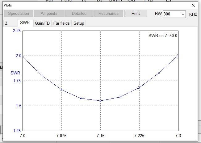 For comparison, here is the calculation done at half that height, 10 meters above ground (antenna shortened to 20.04M long to get best SWR at 7.15MHz):  As it gets closer to the ground, the bandwidth get's narrower. At 5 meters above ground, it's only below 2:1 SWR from 7.075 to 7.240 or so. |
|
|
|
TN, USA
|
[#12]
Originally Posted By Gamma762: Curious what you are measuring SWR with? I would expect a full size 40m dipole to cover the entire 7.0 to 7.3 range under 2.0 at a reasonable height over ground. When talking about element diameters for common antenna types it's not the diameter per se, it's the length to diameter ratio. Different wire gauges look different on a 1.2GHz antenna. At HF, the lengths are so long that changing wire gauge doesn't change the ratio enough to make a noticeable effect. both a NanoVNA and a rigExpert aa230-zoom which gave same answer to 2 decimal places. also both antennae were same height, hung from same cords, about 16' above the ground. (my 40' pole broke so i'm just using 2 trees now.) |
|
|
|
[#13]
Originally Posted By taliv: both a NanoVNA and a rigExpert aa230-zoom which gave same answer to 2 decimal places. also both antennae were same height, hung from same cords, about 16' above the ground. (my 40' pole broke so i'm just using 2 trees now.) Also playing a bit of a part here is to remember that you're feeding a half-wave center-fed dipole, which has a characteristic impedance of about 72 Ohms, with 50 Ohm coax, so even at the lowest tuned SWR point, you can't get better than about a 1.5:1. |
|
|
|
|
[#14]
Originally Posted By D_Man: So that about tracks with my modeling data, you're just under 5 meters above ground, and have a bandwidth of about +/- 0.075 Mhz from center frequency. Also playing a bit of a part here is to remember that you're feeding a half-wave center-fed dipole, which has a characteristic impedance of about 72 Ohms, with 50 Ohm coax, so even at the lowest tuned SWR point, you can't get better than about a 1.5:1. Originally Posted By D_Man: Originally Posted By taliv: both a NanoVNA and a rigExpert aa230-zoom which gave same answer to 2 decimal places. also both antennae were same height, hung from same cords, about 16' above the ground. (my 40' pole broke so i'm just using 2 trees now.) Also playing a bit of a part here is to remember that you're feeding a half-wave center-fed dipole, which has a characteristic impedance of about 72 Ohms, with 50 Ohm coax, so even at the lowest tuned SWR point, you can't get better than about a 1.5:1. Lower height dipoles are closer to 50 ohms than 70 generally. |
|
|
|
|
[Last Edit: D_Man]
[#15]
Originally Posted By Gamma762: Lower height dipoles are closer to 50 ohms than 70 generally. True, actually at OPs height of about 1/8th a wavelength above ground, it's probably closer to 30 Ohms at the feed point. Either way, if OP can get that wire up higher, it should improve both bandwidth and performance overall. |
|
|
|
TN, USA
|
[#16]
Originally Posted By D_Man: So that about tracks with my modeling data, you're just under 5 meters above ground, and have a bandwidth of about +/- 0.075 Mhz from center frequency. Also playing a bit of a part here is to remember that you're feeding a half-wave center-fed dipole, which has a characteristic impedance of about 72 Ohms, with 50 Ohm coax, so even at the lowest tuned SWR point, you can't get better than about a 1.5:1. Thanks that’s interesting. Tried all kinds of tuning and never got anything below 1.45 and almost everything was 1.55 and up |
|
|
TN, USA
|
[#17]
Unfortunately I don’t have any trees next to me that are going to let me get significantly higher. I’ll eventually build a legit tower but for now I’m planning to go back to a 40’ or so pole
|
|
|
|
[#18]
I have found that longer than wave length non-resonant antennas are much wider than resonant dipoles or 1/4w verticals. For instance, the usable bandwidth on my 80m delta loop on 15m is a mile wide where on my cobweb it's about 200kHz.
|
|
|
|
|
[#19]
The longer the wire, the more the SWR drops for higher frequencies. This is a nanovna scan of my 40m dipole from 7MHz to 500MHz. You can see high SWR in the beginning for anything other than odd harmonics (1/2, 3/2, 5/2, ...) but the longer you go the lower the highs get. This antenna works on 6m, 70cm and surprisingly well on 2m.
|
|
|
|
 Win a FREE Membership!
Sign up for the ARFCOM weekly newsletter and be entered to win a free ARFCOM membership. One new winner* is announced every week!
You will receive an email every Friday morning featuring the latest chatter from the hottest topics, breaking news surrounding legislation, as well as exclusive deals only available to ARFCOM email subscribers.

AR15.COM is the world's largest firearm community and is a gathering place for firearm enthusiasts of all types.
From hunters and military members, to competition shooters and general firearm enthusiasts, we welcome anyone who values and respects the way of the firearm.

Subscribe to our monthly Newsletter to receive firearm news, product discounts from your favorite Industry Partners, and more.
Copyright © 1996-2024 AR15.COM LLC. All Rights Reserved.
Any use of this content without express written consent is prohibited.
AR15.Com reserves the right to overwrite or replace any affiliate, commercial, or monetizable links, posted by users, with our own.