


OFFICIAL Print/Parts/CAD request thread. All part/CAD requests go through this thread! (Page 5 of 18)

|
Originally Posted By mohawk17: Can anyone make me a cookie cutter? My daughter is wanting to make these, and they require printing off a stencil and cutting them out. A cookie cutter would be way betterhttps://www.ar15.com/media/mediaFiles/293682/16364212216785803377794919491443_jpg-2160107.JPG https://www.thingiverse.com/thing:2662093 I'm gonna have to print one now. lol... |

|
STL #1 STL #2 Updated STL's of the prior request, dimensions should be accurate. Holy crap, self teaching yourself the basics of Fusion 360 is a freaking TRIP. I am seeing wireframes and constraints all over my house now. Attached File Attached File Once again, I am willing to pay to have a few of each made. |

|
Cool thread! I’ve got a printer and have been teaching myself CAD. I definitely could have designed that vac coupler for the wood shop. I've made some for my own shop. So custom couplers are right in my wheelhouse. Will continue to follow this thread in hopes of helping someone out. |
|
Originally Posted By pokey074: https://www.ar15.com/media/mediaFiles/1073/7B9913F7-E7FE-46EF-9B34-433D41532E40_jpe-1790782.JPG Can anyone make me a cupholder insert? I will gladly pay you for your time/materials. Here's what I'm looking for: Base 3" outside diameter, 4" tall. That fits in my existing cupholder. Top part needs to be right around 3.75" inside diameter, Transition doesn't necessarily need to be angled. Base edges can be chamfered. Ive tried a couple of things from Amazon but none of them are tall enough in the base. Thanks in advance. @pokey074 Did anyone end up making one of these for you? ETA: I’m no CAD guru. But these sorts of things are my right in my wheelhouse. How’s this look? Attached File I went with a .08” wall thickness. Doesn’t sound like much. But I print and sell couplers for dust collection that are nearly identical to this. And haven’t had anyone alert me of issues. Also, what are the temp swings going to be like in the environment where this will be used/stored? As far as tolerance, how close to you need it to be to those exact I.D. and O.D. values? My printer typically hits a +/- .005” accuracy. |

|
Originally Posted By CheckYourself: @pokey074 Did anyone end up making one of these for you? ETA: I'm no CAD guru. But these sorts of things are my right in my wheelhouse. How's this look? https://www.ar15.com/media/mediaFiles/460645/992BED15-B50D-4672-9FB6-170993EDC480_png-2183881.JPG I went with a .08" wall thickness. Doesn't sound like much. But I print and sell couplers for dust collection that are nearly identical to this. And haven't had anyone alert me of issues. Also, what are the temp swings going to be like in the environment where this will be used/stored? As far as tolerance, how close to you need it to be to those exact I.D. and O.D. values? My printer typically hits a +/- .005" accuracy. Originally Posted By CheckYourself: Originally Posted By pokey074: https://www.ar15.com/media/mediaFiles/1073/7B9913F7-E7FE-46EF-9B34-433D41532E40_jpe-1790782.JPG Can anyone make me a cupholder insert? I will gladly pay you for your time/materials. Here's what I'm looking for: Base 3" outside diameter, 4" tall. That fits in my existing cupholder. Top part needs to be right around 3.75" inside diameter, Transition doesn't necessarily need to be angled. Base edges can be chamfered. Ive tried a couple of things from Amazon but none of them are tall enough in the base. Thanks in advance. @pokey074 Did anyone end up making one of these for you? ETA: I'm no CAD guru. But these sorts of things are my right in my wheelhouse. How's this look? https://www.ar15.com/media/mediaFiles/460645/992BED15-B50D-4672-9FB6-170993EDC480_png-2183881.JPG I went with a .08" wall thickness. Doesn't sound like much. But I print and sell couplers for dust collection that are nearly identical to this. And haven't had anyone alert me of issues. Also, what are the temp swings going to be like in the environment where this will be used/stored? As far as tolerance, how close to you need it to be to those exact I.D. and O.D. values? My printer typically hits a +/- .005" accuracy. |

|
Can anyone print this in gold for me? Looking for someone that has there printing dialed in and can provide a smooth finish. https://www.thingiverse.com/thing:4571138 Thanks! |

|
Quick update on the gear Rat_Patrol made from carbon fiber PETG. My sons been shooting his ultra a lot. Both with darts and without. Without creates a lot more force on the gear system as there's no back pressure to slow the system down. The gears are still running smooth as the day we got them put in. Again, thanks to @Rat_Patrol & @-Obsessed- for getting my son up and running again. Take care, Doc |
Si Vis Pacem Para Bellum

Easily irritated engineer of odd things
Joined:
Jul 2008
Posts:
19255
EE: 100% (5)
 MN, USA
|
Originally Posted By SenditDoc: Quick update on the gear Rat_Patrol made from carbon fiber PETG. My sons been shooting his ultra a lot. Both with darts and without. Without creates a lot more force on the gear system as there's no back pressure to slow the system down. The gears are still running smooth as the day we got them put in. Again, thanks to @Rat_Patrol & @-Obsessed- for getting my son up and running again. Take care, Doc |
Strong men create good times. Good times breed weak men. Weak men create hard times. Hard times breed strong men.

|
Originally Posted By SenditDoc: Quick update on the gear Rat_Patrol made from carbon fiber PETG. My sons been shooting his ultra a lot. Both with darts and without. Without creates a lot more force on the gear system as there's no back pressure to slow the system down. The gears are still running smooth as the day we got them put in. Again, thanks to @Rat_Patrol & @-Obsessed- for getting my son up and running again. Take care, Doc That's awesome! Glad to hear it, and we are very happy to help. I put some of that CF PETG on my Christmas list. Which means either way I'll have it by the new year. 
|



|
Originally Posted By Requiem: I'm looking for a stl of an ar15 lower that I can install a LPK and grip just for dryfiring. Please and much appreciated! I have ender 5 Plus. Similar to Larue's TAC https://static.larue.com/media/prodthumbs/24/fd/24fde31858a3e0f7804157c8b35a2048.jpg @CheckYourself |
post_count += 1
PGP: 912E3E9A194DED4E47DA0BA9D593AD70C8C12B9C
PGP: 912E3E9A194DED4E47DA0BA9D593AD70C8C12B9C
|
Originally Posted By scul: @CheckYourself Originally Posted By scul: Originally Posted By Requiem: I'm looking for a stl of an ar15 lower that I can install a LPK and grip just for dryfiring. Please and much appreciated! I have ender 5 Plus. Similar to Larue's TAC https://static.larue.com/media/prodthumbs/24/fd/24fde31858a3e0f7804157c8b35a2048.jpg @CheckYourself You rang? @Requiem Here's the one I've been using for a trigger mod project I'm working on. Link has both the STL and STEP files. Both free. https://www.prusaprinters.org/prints/62954-ar-15-trigger-jig-v15 I printed it upright (i.e. front of the trigger guard on the print bed). In that orientation, the layer lines run parallel to the force of the hammer falling. So it won't handle dry firing more than a few times before delaminating. I didn't mind for my application. And I printed it that way because I was able to do it with zero supports. If you plan to truly dry fire with it. I would suggest printing it with so that the layer lines run perpendicular to the hammer's inertia. Even then, I can't confirm if that'll make it strong enough to allow for continued dry firing. I want to test that, but just haven't done it yet. If you try that and it still cracks, having access to the STEP file is nice. As you can modify it to maybe include something to better tolerate the hammer blows. I have a modified one printing right now. But for different reasons. Chose to print it in the upright orientation again. Because I'm willing to accept the tradeoff of less strength in favor of no supports. |
|
Originally Posted By Requiem: Much obliged, thanks! I just got my 3d printer last week so I'll learn on other stuff before trying to figure out how to make this stronger for repeated dryfires. No problem  Enjoy the new printer! There'll definitely be a learning curve. Just keep at it. My suggestion would be to get it dialed in and printing first (if you plan to learn CAD). And there's no problem with trying different slicers down the road. But start with one. Cura would be my recommendation. Not because it's the best. But because there are a boatload of setting tutorials out there to get you in the ballpark. I will say, that trigger jig is an outstanding model. And prints beautifully if you orient it on its face. I did however have to open up the pocket a little for my Larue MBT2s. That's a pretty meaty trigger shoe, and needed a little more breathing room. Just used a dremel at a low speed. Didn't take much. |

|
Can anyone print a AR15 ejector removal jig for me? Preferably one with a lug slot that positions the roll pin vertically....and another hole deep enough to capture the roll pin when tapped free. Something like this: 
|
Never confuse motion with progress; never confuse a college degree with intelligence.
Easily irritated engineer of odd things
Joined:
Jul 2008
Posts:
19380
EE: 100% (5)
MN, USA
|
Originally Posted By Creature: Can anyone print a AR15 ejector removal jig for me? Preferably one with a lug slot that positions the roll pin vertically....and another hole deep enough to capture the roll pin when tapped free. Something like this: https://www.ar15.com/media/mediaFiles/153820/Screenshot_20211214-122756_DuckDuckGo-2203811.jpg |
Strong men create good times. Good times breed weak men. Weak men create hard times. Hard times breed strong men.

| Tineye found an Etsy listing with that pic. A Thingiverse version can be found at https://www.thingiverse.com/thing:3695058 |
|
Originally Posted By Rat_Patrol: Can you locate the file? Originally Posted By Rat_Patrol: Originally Posted By Creature: Can anyone print a AR15 ejector removal jig for me? Preferably one with a lug slot that positions the roll pin vertically....and another hole deep enough to capture the roll pin when tapped free. Something like this: https://www.ar15.com/media/mediaFiles/153820/Screenshot_20211214-122756_DuckDuckGo-2203811.jpg The pic I attached in my post is just a pic I found doing a Google image search. I searched for 3d templates and could only find two that are sort of similar: https://www.thingiverse.com/thing:3460790 https://www.thingiverse.com/thing:3695058 Something I don't see in either is a lug slot for aligning the bolt...or a base under where the bolt lays that is thick enough to freely capture the roll pin. Can these plans be modified? |
Never confuse motion with progress; never confuse a college degree with intelligence.
Easily irritated engineer of odd things
Joined:
Jul 2008
Posts:
19384
EE: 100% (5)
MN, USA
|
I'd be happy to print it, but I don't have time to modify any models. Just let me know what file to print, and I'll print it with carbon fiber PETG |
Strong men create good times. Good times breed weak men. Weak men create hard times. Hard times breed strong men.
|
Originally Posted By Creature: The pic I attached in my post is just a pic I found doing a Google image search. I searched for 3d templates and could only find two that are sort of similar: https://www.thingiverse.com/thing:3460790 https://www.thingiverse.com/thing:3695058 Something I don't see in either is a lug slot for aligning the bolt...or a base under where the bolt lays that is thick enough to freely capture the roll pin. Can these plans be modified? Originally Posted By Rat_Patrol: I'd be happy to print it, but I don't have time to modify any models. Just let me know what file to print, and I'll print it with carbon fiber PETG If Creature isn't in a hurry, I could modify the file for you to print RP. Creature, how quickly you looking to get one of these? Do you just need a lug at the bottom of the bolt lug section that will engage the lugs on the bolt to hold it upright? And then just a hollowed out section in the base where the roll pin falls? |
|
No rush. Yes to both mods as you described: a lug slot so that roll pin is oriented vertically and to prevent the bolt from rotating. And a pocket for the roll pin to drop into freely. Those mods would be appreciated greatly!
|
Never confuse motion with progress; never confuse a college degree with intelligence.
|
Originally Posted By CheckYourself: No problem Enjoy the new printer! There'll definitely be a learning curve. Just keep at it. My suggestion would be to get it dialed in and printing first (if you plan to learn CAD). And there's no problem with trying different slicers down the road. But start with one. Cura would be my recommendation. Not because it's the best. But because there are a boatload of setting tutorials out there to get you in the ballpark. I will say, that trigger jig is an outstanding model. And prints beautifully if you orient it on its face. I did however have to open up the pocket a little for my Larue MBT2s. That's a pretty meaty trigger shoe, and needed a little more breathing room. Just used a dremel at a low speed. Didn't take much. @checkyourself You're right that the way I printed it wouldnt last long. 3 squeezes of trigger and it snapped.    
|
|
Originally Posted By Requiem: @checkyourself You're right that the way I printed it wouldnt last long. 3 squeezes of trigger and it snapped. https://i.imgur.com/Ej9Hsj9.jpg https://i.imgur.com/4aG9I50.jpg https://i.imgur.com/W1MV2kL.jpg https://i.imgur.com/7UzbMpu.jpg Yeah. It may hold up better printed in a different orientation. But I really think it would like require some mods to the STEP file for any long term use. |
|
Originally Posted By Creature: No rush. Yes to both mods as you described: a lug slot so that roll pin is oriented vertically and to prevent the bolt from rotating. And a pocket for the roll pin to drop into freely. Those mods would be appreciated greatly! @Creature just as an update those two designs are rather bad and after printing a PLA sample I'm going to scrap them and just create you one from scratch as it would be quicker. Hope to have a prototype drawn up and printed by Christmas and then I can send it off to RP for printing as he has CFPETG. I have regular PETG but admittedly the CF would be a better material in this instance. |
|
Originally Posted By -Obsessed-: @Creature just as an update those two designs are rather bad and after printing a PLA sample I'm going to scrap them and just create you one from scratch as it would be quicker. Hope to have a prototype drawn up and printed by Christmas and then I can send it off to RP for printing as he has CFPETG. I have regular PETG but admittedly the CF would be a better material in this instance. Thank you! I am very much obliged! 
|
Never confuse motion with progress; never confuse a college degree with intelligence.
|
Originally Posted By Creature: @-Obsessed- Thank you! I am very much obliged! @Creature First proof of concept has been proven. Almost too well. Took forever to get it out.  Anywho, printing a final, complete mockup now with a threaded screw assembly (not unlike the others) to depress the ejector. However in this design the lugs on the bottom that you see here actually lock the bolt firmly in place, and will allow different bolt faces to work without modifying the screw or jig. So this should work with any AR15 bolt. Attached File |
|
@Creature Done.  Really happy with how it turned out if I do say so myself. Wound up designing my own threads. Printed threads don't work well out of a CAD toolbox it turns out.  The tolerances, even on coarse threads, are much too tight. The tolerances, even on coarse threads, are much too tight.Printed in three pieces. The base, a threaded insert for the base, and the screw to depress the ejector. The tail of the bolt sticks out intentionally so you can press it against the table to pop the bolt out of the jig. It's a snug fit, but not overly tight, at least on my printer using PETG. @Rat_Patrol I'll post this on PrusaPrinters and share the link and you can snag them from there if that works for you. ETA: Link to PrusaPrinters Attached File |

|
Originally Posted By -Obsessed-: @Creature Done. Really happy with how it turned out if I do say so myself. Wound up designing my own threads. Printed threads don't work well out of a CAD toolbox it turns out. The tolerances, even on coarse threads, are much too tight.Printed in three pieces. The base, a threaded insert for the base, and the screw to depress the extractor. The tail of the bolt sticks out intentionally so you can press it against the table to pop the bolt out of the jig. It's a snug fit, but not overly tight, at least on my printer using PETG. @Rat_Patrol I'll post this on PrusaPrinters and share the link and you can snag them from there if that works for you. ETA: Link to PrusaPrinters https://www.ar15.com/media/mediaFiles/467079/20211221_091727_jpg-2211527.JPG Thanks, I DLed |
"Those who would give up essential Liberty, to purchase a little temporary Safety, deserve neither Liberty nor Safety." -Benjamin Franklin
[FPC]
RIP WMD
RIP TerryC
[FPC]
RIP WMD
RIP TerryC
Easily irritated engineer of odd things
Joined:
Jul 2008
Posts:
19460
EE: 100% (5)
MN, USA
|
Originally Posted By -Obsessed-: @Creature Done. Really happy with how it turned out if I do say so myself. Wound up designing my own threads. Printed threads don't work well out of a CAD toolbox it turns out. The tolerances, even on coarse threads, are much too tight.Printed in three pieces. The base, a threaded insert for the base, and the screw to depress the extractor. The tail of the bolt sticks out intentionally so you can press it against the table to pop the bolt out of the jig. It's a snug fit, but not overly tight, at least on my printer using PETG. @Rat_Patrol I'll post this on PrusaPrinters and share the link and you can snag them from there if that works for you. ETA: Link to PrusaPrinters https://www.ar15.com/media/mediaFiles/467079/20211221_091727_jpg-2211527.JPG |
Strong men create good times. Good times breed weak men. Weak men create hard times. Hard times breed strong men.
Easily irritated engineer of odd things
Joined:
Jul 2008
Posts:
19461
EE: 100% (5)
MN, USA
|
Originally Posted By -Obsessed-: Maybe the wife got me CF PETG for Christmas. Either way I'll have some by mid January. I love PETG so how much more I should love CF reinforced. |
Strong men create good times. Good times breed weak men. Weak men create hard times. Hard times breed strong men.
|
Originally Posted By -Obsessed-: Maybe the wife got me CF PETG for Christmas. Either way I'll have some by mid January. I love PETG so how much more I should love CF reinforced. Originally Posted By -Obsessed-: Originally Posted By Rat_Patrol: I'm on it. Maybe the wife got me CF PETG for Christmas. Either way I'll have some by mid January. I love PETG so how much more I should love CF reinforced. @Rat_Patrol Wow that prototype came out awesome! |
Never confuse motion with progress; never confuse a college degree with intelligence.

|
Originally Posted By Creature: @-Obsessed- @Rat_Patrol Wow that prototype came out awesome! Wow. Someone requested a random picture off the internet with no effort to even find the STL file or do any of the CAD work, and you two really put in the effort. I greatly appreciate the time it took to design and develop the prototype. The requestor should at least send you a roll of CF, IMHO. |
|
Originally Posted By EEnginerd: Wow. Someone requested a random picture off the internet with no effort to even find the STL file or do any of the CAD work, and you two really put in the effort. I greatly appreciate the time it took to design and develop the prototype. The requestor should at least send you a roll of CF, IMHO. Happy to help. No Filament necessary.
|
Easily irritated engineer of odd things
Joined:
Jul 2008
Posts:
19466
EE: 100% (5)
MN, USA
|
Originally Posted By EEnginerd: Wow. Someone requested a random picture off the internet with no effort to even find the STL file or do any of the CAD work, and you two really put in the effort. I greatly appreciate the time it took to design and develop the prototype. The requestor should at least send you a roll of CF, IMHO. Originally Posted By EEnginerd: Originally Posted By Creature: @-Obsessed- @Rat_Patrol Wow that prototype came out awesome! Wow. Someone requested a random picture off the internet with no effort to even find the STL file or do any of the CAD work, and you two really put in the effort. I greatly appreciate the time it took to design and develop the prototype. The requestor should at least send you a roll of CF, IMHO. I've done almost nothing 
|
Strong men create good times. Good times breed weak men. Weak men create hard times. Hard times breed strong men.
|
Originally Posted By EEnginerd: Wow. Someone requested a random picture off the internet with no effort to even find the STL file or do any of the CAD work, and you two really put in the effort. I greatly appreciate the time it took to design and develop the prototype. The requestor should at least send you a roll of CF, IMHO. I would be happy to do so. |
Never confuse motion with progress; never confuse a college degree with intelligence.



|
@AlphaThree Done! Took me a lot longer than I wanted. The design is rather complex actually, with multiradius fillets, projected debossing, and the fastener holes are angled, and in different directions each on their own plane. That said I feel I got a darn near perfect replica. The only thing that isn't exact is the debossed pattern. The original uses a radially projected pattern, which creates exaggerated features on the curves. Instead of radially projecting the debossing I chose to wrap it instead. You'll see the difference if you look near the front "hook" - the replica has a "normal" sized debossed oval vs the exaggerated shape on the original. That said, if anyone is willing to print this out of some hard TPU I'd be happy to pass along any of the files. Also AlphaThree if you want the files for future reference happy to send to you as well. Attached File Attached File Attached File Attached File |

|
Originally Posted By -Obsessed-: @AlphaThree Done! Took me a lot longer than I wanted. The design is rather complex actually, with multiradius fillets, projected debossing, and the fastener holes are angled, and in different directions each on their own plane. That said I feel I got a darn near perfect replica. The only thing that isn't exact is the debossed pattern. The original uses a radially projected pattern, which creates exaggerated features on the curves. Instead of radially projecting the debossing I chose to wrap it instead. You'll see the difference if you look near the front "hook" - the replica has a "normal" sized debossed oval vs the exaggerated shape on the original. That said, if anyone is willing to print this out of some hard TPU I'd be happy to pass along any of the files. Also AlphaThree if you want the files for future reference happy to send to you as well. https://www.ar15.com/media/mediaFiles/467079/20220107_100423_jpg-2231548.JPG https://www.ar15.com/media/mediaFiles/467079/20220107_100432_jpg-2231550.JPG https://www.ar15.com/media/mediaFiles/467079/20220107_100501_jpg-2231551.JPG https://www.ar15.com/media/mediaFiles/467079/20220107_100527_jpg-2231555.JPG Incredible! |
Easily irritated engineer of odd things
Joined:
Jul 2008
Posts:
19635
EE: 100% (5)
MN, USA
Easily irritated engineer of odd things
Joined:
Jul 2008
Posts:
19639
EE: 100% (5)
MN, USA
 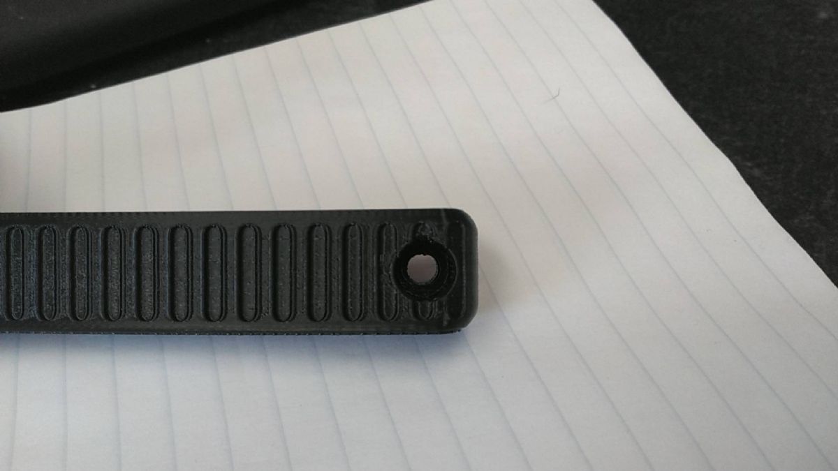 @-Obsessed- Nice design, as usual! No mods were needed, printed just fine with TPU. @AlphaThree If you like it, IM me your mailing address so I can figure postage. I made with with a flexible TPU filament, so it has some squish in it |
Strong men create good times. Good times breed weak men. Weak men create hard times. Hard times breed strong men.

Has anyone designed a projectile for a golf ball canon? (other than a gold ball, thinking something along a rifle round). 1.68 is a standard gold ball, perhaps hollow inside so that it could be filled with concrete or plaster ( I have seen guys build projectiles out of PVC and funnels but 3d would be so much better.) We have an annual cannon shoot at the club for accuracy. I looked on thing universe but couldn't find anything. open to suggestions and improvements etc. Here is a picture of my cannon 
|
GOA-Life Member, SAF-Life Member
NRA-Benefactor Life Member, RSO
Member ARPC, BRRC, BEGRC, IDPA (CSO), USPSA
Certified Instructor, Armorer, Engineer, & Professional
NRA-Benefactor Life Member, RSO
Member ARPC, BRRC, BEGRC, IDPA (CSO), USPSA
Certified Instructor, Armorer, Engineer, & Professional
|
Originally Posted By Thunder69Storm: Has anyone designed a projectile for a golf ball canon? (other than a gold ball, thinking something along a rifle round). 1.68 is a standard gold ball, perhaps hollow inside so that it could be filled with concrete or plaster ( I have seen guys build projectiles out of PVC and funnels but 3d would be so much better.) We have an annual cannon shoot at the club for accuracy. I looked on thing universe but couldn't find anything. open to suggestions and improvements etc. https://www.ar15.com/media/mediaFiles/203479/Berger30cal-2243969.jpg Here is a picture of my cannon https://www.ar15.com/media/mediaFiles/203479/85AE0611-741A-484E-BF6B-BD0994EFD20B-2243881.jpg Length? Do you prefer an open meplat in which to fill from or would you prefer to fill from the tail? What weight you hoping for? |
|
Any chance of a larger version for an AR10 bolt? |
Never confuse motion with progress; never confuse a college degree with intelligence.