


OFFICIAL Print/Parts/CAD request thread. All part/CAD requests go through this thread! (Page 18 of 18)

|
Originally Posted By Rat_Patrol: Depends on the slicer. Better of starting a thread if you are looking for help on how to do it. Originally Posted By Rat_Patrol: Originally Posted By ThatGuyTheCooler: How do i paint fuzzy skin (grip texture) in a specific area. I want to add the recessed outline and add grip inside. This tavor grip: https://imgdump5.novarata.net/800x941/0vyyuz.png this style fuzzy skin: https://imgdump5.novarata.net/800x941/1h32td.png I thought this was the thread for exactly that... no one has offered help so far |

  I have a project, and I'm looking for an AR compatible grip that looks like this. It's from the M41A Pulse Rifle from Aliens. The original was made from a modified Thompson, but clearly the grip looks different. Anyone able to design an AR grip in this style? Thank you! |

|
Originally Posted By ThatGuyTheCooler: I thought this was the thread for exactly that... no one has offered help so far If the model has clearly defined zones then you can use the fill tool in the fuzzy skin painting command. If not, then you have to carefully paint them on manually. If you have the cad file then you can model some solids where you want the texture to be then import them into the slicer and set them to fuzzy skin modifiers. You could also try using https://bumpmesh.com/ for a wider variety of texture options. |

|
Originally Posted By Scrapple: https://i.ibb.co/Psh8Gzqh/Screenshot-20260714-032936-Chrome.jpg https://i.ibb.co/kgtSCQXg/Screenshot-20260715-121017-Chrome.jpg I have a project, and I'm looking for an AR compatible grip that looks like this. It's from the M41A Pulse Rifle from Aliens. The original was made from a modified Thompson, but clearly the grip looks different. Anyone able to design an AR grip in this style? Thank you! 
|
|
Originally Posted By D_Man: Whipped this up real quick, gave it a bit of a widening taper as it goes down, could make some edits as needed? https://www.ar15.com/media/mediaFiles/157876/2q5uquhj-3796292.png Hell yeah! That's looking great already. Very nicely done. Can I message you about making me one please? |

Nothing lasts forever but the earth and sky
Joined:
Dec 2000
Posts:
10734
EE: 100% (204)
 USA
USA
|
Other than buying a couple of items, I'm a total noob to 3D printing so have no idea whether or not this is feasible. I'd like to find out if it's possible to have an insert designed for a Glock +2 kit which will fit in the .380 caliber Glock 25 and 28 mags. The OEM Glock kit has two pieces - the floor plate which will fit all magazines (9mm/.380/.40/.357/.45 GAP), and a magazine insert which fits everything except .380 mags. The .380 mags (which have the same external dimensions as the larger caliber mags) have a smaller cavity as the back is inset into the body as seen in the first pic below. The second pic below shows approximate sizes of the factory parts, and the third shows approximately how much shorter the insert needs to be to fit into the mag. I did experiment with trimming one, but the piece which was removed has a small lip to help keep the spring in placed during assembly, making installation of the trimmed part difficult with less than 3 hands.  I'd like to have a new insert designed which would replicate the original, but just a little bit shorter. I'd like to have a new insert designed which would replicate the original, but just a little bit shorter.Is this possible? If yes, can anyone suggest a place to get some designed and made?   
|

Member
Joined:
Dec 2023
Posts:
916
EE: 100% (30)
SC, USA
|
Came across these end cap wrench's for the OCL Ti22. Hoping someone can print me one?  makerworld.com Link |

|
Originally Posted By dsm600rr: Came across these end cap wrench's for the OCL Ti22. Hoping someone can print me one? makerworld.com Link @dsm600rr PM sent. |
post_count += 1
PGP: 912E3E9A194DED4E47DA0BA9D593AD70C8C12B9C
PGP: 912E3E9A194DED4E47DA0BA9D593AD70C8C12B9C
Member
Joined:
Dec 2023
Posts:
917
EE: 100% (30)
SC, USA


|
NOOB here looking to have a part modeled and printed, maybe 2-3 pieces with slightly different dimensions to see how they fit. I want to make a blade that fits into a receiver plate so I can convert the table leg holder into a flagpole holder. If this is beyond the intent of this thread, please point me in the correct direction. This link has some pictures showing what I am trying to emulate, along with the receiver plate it fits into. Pics of my part The part is basically a 1/4" thick trapezoid 3.125" (wide edge) x 2.625" (narrow edge) x 3" tall. It has a 0.875" tall notch in each side and a 3/4" hole in the center, all of which are equidistant top to bottom. There are 1/8" wide chamfers running down the sides and the corners are rounded. What would it take for me to get a CAD model and then a sample part (ideally three parts, one nominal and +/- sizes)? 
|
|
Originally Posted By tangbang: NOOB here looking to have a part modeled and printed, maybe 2-3 pieces with slightly different dimensions to see how they fit. I want to make a blade that fits into a receiver plate so I can convert the table leg holder into a flagpole holder. If this is beyond the intent of this thread, please point me in the correct direction. This link has some pictures showing what I am trying to emulate, along with the receiver plate it fits into. Pics of my part The part is basically a 1/4" thick trapezoid 3.125" (wide edge) x 2.625" (narrow edge) x 3" tall. It has a 0.875" tall notch in each side and a 3/4" hole in the center, all of which are equidistant top to bottom. There are 1/8" wide chamfers running down the sides and the corners are rounded. What would it take for me to get a CAD model and then a sample part (ideally three parts, one nominal and +/- sizes)? https://www.ar15.com/media/mediaFiles/83409/IMG_8075_Large-3798813.jpg Here is the CAD model. (Might need an OnShape account to view... not sure.) I didn't see dims for the 4 corner chamfers and the chamfers on the cutouts, so I took some guesses, but looks like they aren't critical. I also did the fillet at 0.25x0.125 vs the spec'd 0.125x0.125 as the pictures seem to show a full thickness on the fillet. All those are simple to change. Let me know if changes are needed. Unfortunately, I am going out of town soon, so I can't print these off for you. Someone else can print them if they'd like, or I can get them when I get back. Side note, are these proof of concept before getting them machined in metal? I don't think a 3D print would be strong enough, and would be difficult to attach a pole as is.  |
post_count += 1
PGP: 912E3E9A194DED4E47DA0BA9D593AD70C8C12B9C
PGP: 912E3E9A194DED4E47DA0BA9D593AD70C8C12B9C
|
Originally Posted By scul: Here is the CAD model. (Might need an OnShape account to view... not sure.) I didn't see dims for the 4 corner chamfers and the chamfers on the cutouts, so I took some guesses, but looks like they aren't critical. I also did the fillet at 0.25x0.125 vs the spec'd 0.125x0.125 as the pictures seem to show a full thickness on the fillet. All those are simple to change. Let me know if changes are needed. Unfortunately, I am going out of town soon, so I can't print these off for you. Someone else can print them if they'd like, or I can get them when I get back. Side note, are these proof of concept before getting them machined in metal? I don't think a 3D print would be strong enough, and would be difficult to attach a pole as is. https://www.ar15.com/media/mediaFiles/376127/Screenshot_20260721_103958-3798835.png Amazing!! I've been fussing with chatgpt for days trying to get a 2D print and finally decided to post here. BOOM. Yes, proof of concept. I want to see how it will fit into the boat's receiver plate, then bring the design to someone who can laser cut or otherwise fabricate a part out of SS. Eventually I want to figure out a way to attach a flagpole holder. The factory table leg is welded onto the blade. I am thinking about using countersunk bolts from back side into some type of adaptor. Enjoy your vacation and THANK YOU. What type of material would you recommend I use for initial printed part(s)? I know exactly nothing about this except I want to create a flagpole holder that mounts where my table leg mounts. |
|
Originally Posted By tangbang: Amazing!! I've been fussing with chatgpt for days trying to get a 2D print and finally decided to post here. BOOM. Yes, proof of concept. I want to see how it will fit into the boat's receiver plate, then bring the design to someone who can laser cut or otherwise fabricate a part out of SS. Eventually I want to figure out a way to attach a flagpole holder. The factory table leg is welded onto the blade. I am thinking about using countersunk bolts from back side into some type of adaptor. Enjoy your vacation and THANK YOU. What type of material would you recommend I use for initial printed part(s)? I know exactly nothing about this except I want to create a flagpole holder that mounts where my table leg mounts. For just a proof of concept/fit with no load, any material would work. PLA or PETG would be plenty sufficient, though I would print from ABS or ASA only because that's what I typically have loaded. |
post_count += 1
PGP: 912E3E9A194DED4E47DA0BA9D593AD70C8C12B9C
PGP: 912E3E9A194DED4E47DA0BA9D593AD70C8C12B9C

|
Tried using the search function but it doesn't like short search terms... I would imagine someone has already asked about this, so yes, late to the party, but... a large 3D version of the ARFCOM Bolt Face Logo? About 5" diameter or so? and a large 3D version of the 'classic iron sights' logo, also about 5" diameter... |
Be careful when the boss asks "Have you ever been to ...?"
"You got out once. You dip so much as a pinky back into this (ARFCOM) pond... you may well find something reaches out... and drags you back into its depths".
"You got out once. You dip so much as a pinky back into this (ARFCOM) pond... you may well find something reaches out... and drags you back into its depths".
|
Originally Posted By scul: Here is the CAD model. (Might need an OnShape account to view... not sure.) I didn't see dims for the 4 corner chamfers and the chamfers on the cutouts, so I took some guesses, but looks like they aren't critical. I also did the fillet at 0.25x0.125 vs the spec'd 0.125x0.125 as the pictures seem to show a full thickness on the fillet. All those are simple to change. Let me know if changes are needed. Unfortunately, I am going out of town soon, so I can't print these off for you. Someone else can print them if they'd like, or I can get them when I get back. Side note, are these proof of concept before getting them machined in metal? I don't think a 3D print would be strong enough, and would be difficult to attach a pole as is. https://www.ar15.com/media/mediaFiles/376127/Screenshot_20260721_103958-3798835.png I would like to make some changes to the blade : For my purposes, I see no reason for the .750” hole in the center. I would like to remove that feature. Also, I would like to model the pole holder directly into the blade as one part (is that printable?) This is my sketch, starting from the blade already modeled above (but without the hole), to accommodate 1” OD flag pole. 1/8” drain hole at the bottom (is this something I drill out myself?) Can this be modeled?  |
|
Originally Posted By tangbang: I would like to make some changes to the blade : For my purposes, I see no reason for the .750” hole in the center. I would like to remove that feature. Also, I would like to model the pole holder directly into the blade as one part (is that printable?) This is my sketch, starting from the blade already modeled above (but without the hole), to accommodate 1” OD flag pole. 1/8” drain hole at the bottom (is this something I drill out myself?) Can this be modeled? https://www.ar15.com/media/mediaFiles/83409/IMG_8086-3800235.jpg I could knock this out tonight unless someone else wants to get to it first. @tangbang Attached File |
Member
Joined:
Dec 2023
Posts:
918
EE: 100% (30)
SC, USA
|
Originally Posted By Blob: I could knock this out tonight unless someone else wants to get to it first. @tangbang https://www.ar15.com/media/mediaFiles/160722/Screenshot_2026-07-24_162141_jpg-3800423.JPG @Blob That looks exactly like what I had in mind - thank you! How do I get a model file? I recently created an onshore account and can view the first iteration of the blade above. How do I get a couple samples printed? Is it something someone here can do or do I send a file to someone / someplace to have it printed? I would like to get it mounted to the boat and drop a flag inside to see what I've missed, or if it works as intended straight away. (I'm wondering if the angle of the flag pole hole works aesthetically with the lines of the boat; maybe it should be raked back 10-15 deg? or if straight vertical looks right) ETA - I will need to add a feature for cross pin or possibly split clamp slot and pinch bolt hole. I need something to capture the flag, so to speak. I am intending to see how it all fits/looks, then hopefully drill a through hole for cross pin. Is there any concern with taking a hand drill to a printed part? |
|
Originally Posted By tangbang: @Blob That looks exactly like what I had in mind - thank you! How do I get a model file? I recently created an onshore account and can view the first iteration of the blade above. How do I get a couple samples printed? Is it something someone here can do or do I send a file to someone / someplace to have it printed? I would like to get it mounted to the boat and drop a flag inside to see what I've missed, or if it works as intended straight away. (I'm wondering if the angle of the flag pole hole works aesthetically with the lines of the boat; maybe it should be raked back 10-15 deg? or if straight vertical looks right) PM sent |
|
Originally Posted By dsm600rr: Huge shutout to @scul Prints are perfect! Thank you very much! Less than 24 hours from request to in the mail - and he sent two. Amazing people around here. Thank you, and glad to help out! |
post_count += 1
PGP: 912E3E9A194DED4E47DA0BA9D593AD70C8C12B9C
PGP: 912E3E9A194DED4E47DA0BA9D593AD70C8C12B9C
|
Originally Posted By tangbang: @Blob That looks exactly like what I had in mind - thank you! How do I get a model file? I recently created an onshore account and can view the first iteration of the blade above. How do I get a couple samples printed? Is it something someone here can do or do I send a file to someone / someplace to have it printed? I would like to get it mounted to the boat and drop a flag inside to see what I've missed, or if it works as intended straight away. (I'm wondering if the angle of the flag pole hole works aesthetically with the lines of the boat; maybe it should be raked back 10-15 deg? or if straight vertical looks right) ETA - I will need to add a feature for cross pin or possibly split clamp slot and pinch bolt hole. I need something to capture the flag, so to speak. I am intending to see how it all fits/looks, then hopefully drill a through hole for cross pin. Is there any concern with taking a hand drill to a printed part? @tangbang let me know if you still need help on this. I modeled vertical and 15* versions, both available at the same OnShape link, and with a hole for a cross-pin (which can be moved vertically where ever needed) 
|
post_count += 1
PGP: 912E3E9A194DED4E47DA0BA9D593AD70C8C12B9C
PGP: 912E3E9A194DED4E47DA0BA9D593AD70C8C12B9C
|
Originally Posted By scul: @tangbang let me know if you still need help on this. I modeled vertical and 15* versions, both available at the same OnShape link, and with a hole for a cross-pin (which can be moved vertically where ever needed) https://i.imgur.com/XuK8Shs.png I sent him a couple pieces but I forgot to add the cross hole
|
I received two samples today from @Blob and hand drilled the holes for cross pins. The samples are at 0 degrees and 10 degrees (flag pole hole to blade). I will be test fitting the blades tomorrow at the lake, and then will post pics later. Pictured here is the 0 degree version.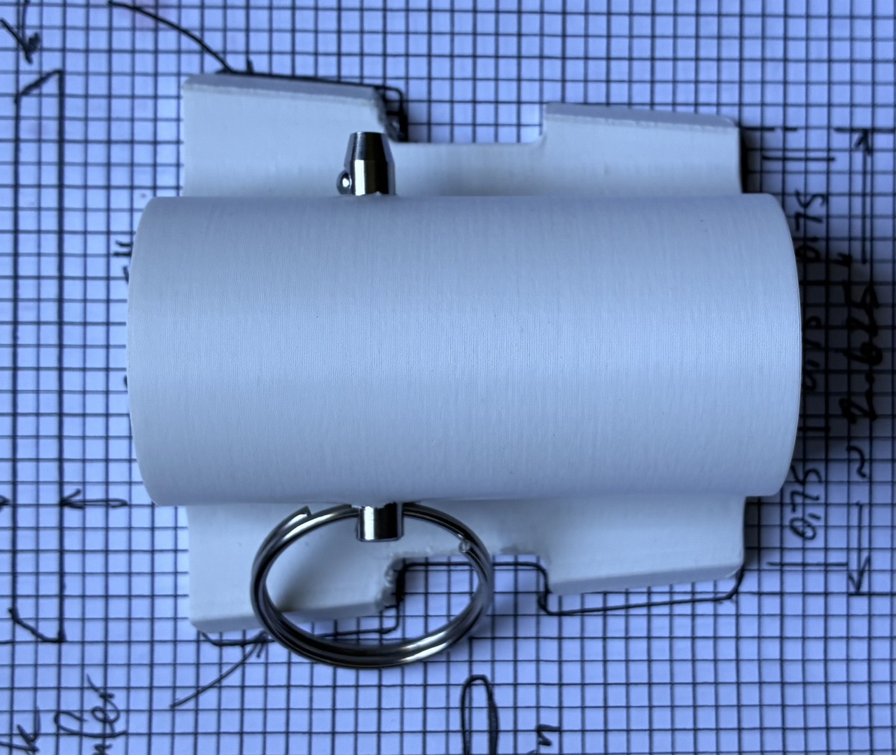  Interesting note - I originally wanted the 10 degree angle to be in different orientation (hole stays parallel to the blade but rotates counter clockwise 10 degrees relative to the blade, I did not communicate this well). The 0 degree hole will likely result in the flag pole extending out over the side of the boat due to the angle of the receiver as it is mounted on the boat - look at the pic here - receiver plate is on the left (as you view the picture). It is hard to tell from the picture but the receiver plate is about 10 degrees from vertical, which would result in the pole extending out over the port side of the boat. I expect the 10 degrees as currently modeled will result in the pole being nearly vertical. 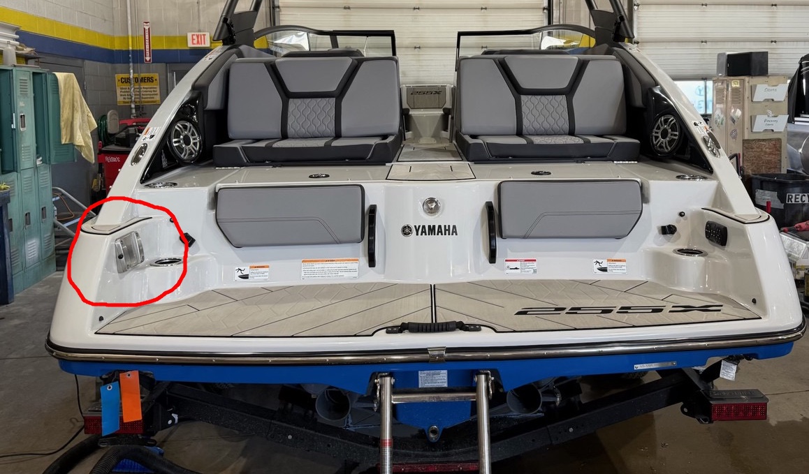 What I thought I wanted (and may still want, if it can be modeled) is for the pole to be swept back ~10 degrees in addition to the current 10 degrees between blade and hole. When I look at flags on boats, they are often 'swept back' as opposed to standing straight up. It might be because most rod holders are angled towards the rear and that is an easy way to mount a flag. My boat does not have rod holders - it is not a fishing boat. It does not have obvious way to mount a flag short of buying some band clamps and rigging something to the wake tower. Some pics here of the receiver and the printed samples. |

|
I have been asked to 3D print some rubber ducks for our team I've been playing with this file for a bit and just can't get what I am trying for I would owe someone huge if you could help me. I need these ducks by next Wednesday Here is the file I am looking to modify https://makerworld.com/en/models/1319773-take-a-hike-duck?from=search#profileId-1355690 I need the beak orange I need this logo on the front of the chest of the duck.  And I need the sign to be brown with red letters that say "Bring It!" Would anyone be willing to help me out please |
Originally Posted By bigbore:
The price for having a dog in your life isn't counted in vet bills and food, its a one time fee paid in tears. Worth every drop.
The price for having a dog in your life isn't counted in vet bills and food, its a one time fee paid in tears. Worth every drop.
|
Originally Posted By MartytW: Tried using the search function but it doesn't like short search terms... I would imagine someone has already asked about this, so yes, late to the party, but... a large 3D version of the ARFCOM Bolt Face Logo? About 5" diameter or so? and a large 3D version of the 'classic iron sights' logo, also about 5" diameter... @MartytW Are you looking for the 3MF/STL file or are you looking to have it printed? |
Originally Posted By bigbore:
The price for having a dog in your life isn't counted in vet bills and food, its a one time fee paid in tears. Worth every drop.
The price for having a dog in your life isn't counted in vet bills and food, its a one time fee paid in tears. Worth every drop.

|
Originally Posted By uafgrad: I have been asked to 3D print some rubber ducks for our team I've been playing with this file for a bit and just can't get what I am trying for I would owe someone huge if you could help me. I need these ducks by next Wednesday Here is the file I am looking to modify https://makerworld.com/en/models/1319773-take-a-hike-duck?from=search#profileId-1355690 I need the beak orange I need this logo on the front of the chest of the duck. https://mazree.blob.core.windows.net/profileimages/39548_Profile.png And I need the sign to be brown with red letters that say "Bring It!" Would anyone be willing to help me out please What help are you looking for? To have someone do all that work, or to have someone do all that work and print them? Or? Theoretically everything you are asking to have done can be done straight in the slicer. SVG of the logo can be imported as a part modifier, and made to be a different color. The beak can be painted directly into the slicer, and the sign can be shaved flat with a negative part modifier, and then have the Bring It! Text added via the text tool. I've done much more complex things than that so know it's possible, but sadly I don't have the time to do it myself as I'm scrambling to get some drawings made for a deck that I just found out I need to have permits in hand before next weekend, so I'm doing that all weekend. 
|
|
Originally Posted By -Obsessed-: What help are you looking for? To have someone do all that work, or to have someone do all that work and print them? Or? Theoretically everything you are asking to have done can be done straight in the slicer. SVG of the logo can be imported as a part modifier, and made to be a different color. The beak can be painted directly into the slicer, and the sign can be shaved flat with a negative part modifier, and then have the Bring It! Text added via the text tool. I've done much more complex things than that so know it's possible, but sadly I don't have the time to do it myself as I'm scrambling to get some drawings made for a deck that I just found out I need to have permits in hand before next weekend, so I'm doing that all weekend. Thanks, I can print them no problem Just having challenges getting the logo on the duck and getting the text on the sign |
Originally Posted By bigbore:
The price for having a dog in your life isn't counted in vet bills and food, its a one time fee paid in tears. Worth every drop.
The price for having a dog in your life isn't counted in vet bills and food, its a one time fee paid in tears. Worth every drop.
|
Originally Posted By uafgrad: @MartytW Are you looking for the 3MF/STL file or are you looking to have it printed? Preferably printed, and I would imagine other folks might like these as well... they make nice wall decor for the Man Cave, or pretty cool coasters... |
Be careful when the boss asks "Have you ever been to ...?"
"You got out once. You dip so much as a pinky back into this (ARFCOM) pond... you may well find something reaches out... and drags you back into its depths".
"You got out once. You dip so much as a pinky back into this (ARFCOM) pond... you may well find something reaches out... and drags you back into its depths".


|
Originally Posted By Busch308: Hello everyone!  I have an old Surefire MR11 rail adapter for Beretta 92's. Unfortunately, the shim was already dust when I got it. Does anyone think they could recreate one or several?https://www.opticsplanet.com/i/80-80-ffffff/[email protected] @Busch308 Do you have a picture or drawing with dimensions for the shim? It would be hard to create a replacement part without reference materials. |
|
For those following my flag pole bracket project for the boat table leg receiver, here are some pics from yesterday. Looks like the 10 degree angle between blade and hole is good, may want to try it at 12 degrees at some point for more vertical pipe. I’m thinking drone launch platform, tube hanger, towel drying rack, go pro mount, etc and for that I would need a vertical pipe. For my flag pole, I think the 10 degree angle between blade and hole looks pretty good with the lines of the boat (see pics). I also think a mild rake backwards (5 or 10 degrees towards back of boat, in addition to the 10 deg b/w blade and hole) will look better than straight vertical for flag pole. Pics here 
|
|
Originally Posted By tangbang: For those following my flag pole bracket project for the boat table leg receiver, here are some pics from yesterday. Looks like the 10 degree angle between blade and hole is good, may want to try it at 12 degrees at some point for more vertical pipe. I’m thinking drone launch platform, tube hanger, towel drying rack, go pro mount, etc and for that I would need a vertical pipe. For my flag pole, I think the 10 degree angle between blade and hole looks pretty good with the lines of the boat (see pics). I also think a mild rake backwards (5 or 10 degrees towards back of boat, in addition to the 10 deg b/w blade and hole) will look better than straight vertical for flag pole. Pics here https://i.postimg.cc/DZn0Nyty/10-bracket-test-fit.jpg Since you paid the wife tax  , here is a design at 12 degree cant with a 10 degree rake... I also made the rake and cant with variables for easy adjustments. , here is a design at 12 degree cant with a 10 degree rake... I also made the rake and cant with variables for easy adjustments.Imgur Album OnShape link |
post_count += 1
PGP: 912E3E9A194DED4E47DA0BA9D593AD70C8C12B9C
PGP: 912E3E9A194DED4E47DA0BA9D593AD70C8C12B9C
|
Latest update on my boat flagpole project. I've received a total of five samples from Blob and scul, two members in this thread; all at different combinations of angles. Scul named the angle called CANT which moves from side to side on the boat. 0 degrees correlates to the blade and the hole being parallel. You can see from the pictures that 0 degrees CANT results in a flag pole sticking off to the port side of the boat due to the angle of the receiver plate as it is mounted to the wall on the port side of the swim deck. The other angle we have been tweaking is referred to RAKE. This is the angle of the flagpole fore and aft relative to the boat. 0 degrees is vertical. 10 degrees causes the flagpole to lean towards the rear of the boat. See pictures. There are a bunch of pictures and videos from today found here; https://postimg.cc/gallery/YhRnBM4 Very encouraging in that it seems one of the printed samples works quite nicely, but will need just a couple tweaks. The 10 degree CANT and the 10 degree RAKe were our best combination, and the flagpole was successfully mounted to the boat all day, at speeds briefly up to 25 mph, albeit after I lashed the flagpole down to a boat cleat (see pics). This is a brief summary of the angles I had available to test today and roughly what they look like when mounted to the boat. 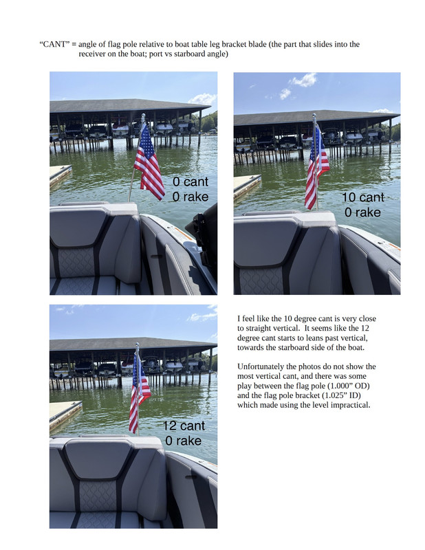 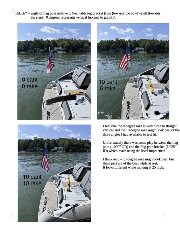  @scul @Blob |
|
Originally Posted By tangbang: Latest update on my boat flagpole project. I've received a total of five samples from Blob and scul, two members in this thread; all at different combinations of angles. Scul named the angle called CANT which moves from side to side on the boat. 0 degrees correlates to the blade and the hole being parallel. You can see from the pictures that 0 degrees CANT results in a flag pole sticking off to the port side of the boat due to the angle of the receiver plate as it is mounted to the wall on the port side of the swim deck. The other angle we have been tweaking is referred to RAKE. This is the angle of the flagpole fore and aft relative to the boat. 0 degrees is vertical. 10 degrees causes the flagpole to lean towards the rear of the boat. See pictures. There are a bunch of pictures and videos from today found here; https://postimg.cc/gallery/YhRnBM4 Very encouraging in that it seems one of the printed samples works quite nicely, but will need just a couple tweaks. The 10 degree CANT and the 10 degree RAKe were our best combination, and the flagpole was successfully mounted to the boat all day, at speeds briefly up to 25 mph, albeit after I lashed the flagpole down to a boat cleat (see pics). This is a brief summary of the angles I had available to test today and roughly what they look like when mounted to the boat. https://i.postimg.cc/13ydbBc0/cant.jpg https://i.postimg.cc/26gJJf2W/rake.jpg https://i.postimg.cc/J0m3t6hq/IMG-5992.jpg @scul @Blob Looks good! Replied to your DM... |
post_count += 1
PGP: 912E3E9A194DED4E47DA0BA9D593AD70C8C12B9C
PGP: 912E3E9A194DED4E47DA0BA9D593AD70C8C12B9C

|
Hello folks. I have the Springfield XDM Elite 3.8 Compact in 9mm and would like to see if there is a solution that could fill the gap between the magazine and backstrap? Attached File |
| Anybody know where I might have a few parts made in 316 SS? I got a lot of fantastic help from a couple users in this thread and now have a working 3D printed model of exactly what I want, but I am not having any success finding someone who will quote making me a few pieces in metal. Some places don't respond back and the one that did never ent a quote. I asked about it and again they said they would quote but once again it has been 10+ days with nothing. Not sure where to turn? Surely there are shops out there that will quote small jobs? |

Easily irritated engineer of odd things
Joined:
Jul 2008
Posts:
32211
EE: 100% (5)
MN, USA
|
Originally Posted By tangbang: Anybody know where I might have a few parts made in 316 SS? I got a lot of fantastic help from a couple users in this thread and now have a working 3D printed model of exactly what I want, but I am not having any success finding someone who will quote making me a few pieces in metal. Some places don't respond back and the one that did never ent a quote. I asked about it and again they said they would quote but once again it has been 10+ days with nothing. Not sure where to turn? Surely there are shops out there that will quote small jobs? |
Once you realize that all power comes from the credible threat of the use of deadly force, and the gov't hates you, most things become easy to understand..


|
I was directed here by some others in the 10-22 sub-forum. I am not a 3D printer or CAD guy but interested and have friends that have printers. I am looking for someone might be able to create (asking for someone to model it and make an STL file) a stock based upon "fictional" image below, Its a PDW stock from an 80s cook book for the 10-22.Attached File The stock, chassis modeled and 3d printed. Use wood grain PLA for the chassis, black PA6-CF for the stock and shroud to closely approximate the look. If anyone can help I would appreciate it - I bet this would also sell well for 10-22 chargers if dimensions were for its length. Edited to Add: perhaps someone might consider the adding to the stock some dimensional aspect for use of existing metal surplus stocks & harware like PM63 retractable stock - looks simiar to the cartoon image.   PPS-43 folding stock - its a tank of a stock, widely around in surplus parts folds tightly on top of a receiver. 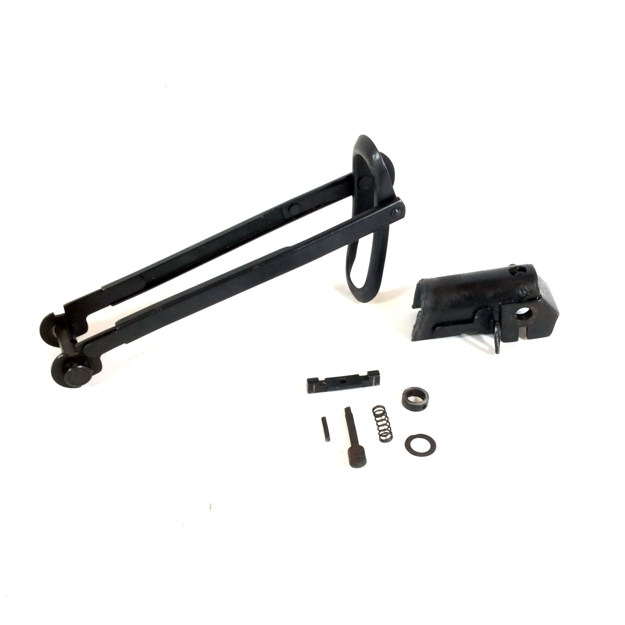 |
Easily irritated engineer of odd things
Joined:
Jul 2008
Posts:
32247
EE: 100% (5)
MN, USA
|
Originally Posted By cherenkov: I was directed here by some others in the 10-22 sub-forum. I am not a 3D printer or CAD guy but interested and have friends that have printers. I am looking for someone might be able to create (asking for someone to model it and make an STL file) a stock based upon "fictional" image below, Its a PDW stock from an 80s cook book for the 10-22.https://www.ar15.com/media/mediaFiles/192012/Exotic_10-22_jpg-3830525.JPG The stock, chassis modeled and 3d printed. Use wood grain PLA for the chassis, black PA6-CF for the stock and shroud to closely approximate the look. If anyone can help I would appreciate it - I bet this would also sell well for 10-22 chargers if dimensions were for its length. Edited to Add: perhaps someone might consider the adding to the stock some dimensional aspect for use of existing metal surplus stocks & harware like PM63 retractable stock - looks simiar to the cartoon image.https://www.apexgunparts.com/media/catalog/product/cache/74c1057f7991b4edb2bc7bdaa94de933/0/4/04jan15_pm63_stk-late_mid_1.jpg https://i0.wp.com/max-arms.com/wp-content/uploads/2022/02/PM63-kit-Select-1-2.jpg?fit=1995%2C1995&ssl=1 PPS-43 folding stock - its a tank of a stock, widely around in surplus parts folds tightly on top of a receiver. https://i.blackmarketarms.com/Custom/Files/2025/10/68dd88665d58d.JPG |
Once you realize that all power comes from the credible threat of the use of deadly force, and the gov't hates you, most things become easy to understand..
|
Originally Posted By Rat_Patrol: I'll let you know that is a huge ask in both time and materials, don't expect to get any takers. And woodgrain pla isn't a thing. No filament will come out looking like wood. I'm not asking for anyone to provide materials - as to actually print of items materials - looking for more of a CAD file starting point. I certainly don't disagree asking someone to do anything is a huge ask - but if there are other like minded people in this forum - its a chance. |