|
Posted: 4/17/2020 4:58:45 PM EDT
I am looking to acquire a set of MG42 Pressure plate gauges but cannot find them anywhere in stock. I have the plans for the gauge from an WWII armorers manual and was thinking about just making one myself. Do you all think its possible to just use a hand file and a protractor to get the angles correct? Also, what does the 200r refer to in the drawing. This is a german manual so units are in mm.
Or is anybody aware of a person/company that will take on small scale jobs like this? Only looking to get about 20 units made. Any thoughts would be appreciated.   |
|
|
|
[#1]
200r looks like the radius of that curve.
|
|
|
|
[#2]
Quoted: 200r looks like the radius of that curve. But has no noted center point so you would be guessing & assuming things to try to figure out exactly where it is. |
|
|
|
[#3]
The 200 mm radius is tangent to the two flat planes which is well defined by the point of intersection. You have 88mm minus 29mm for the point of intersection. To lay this out and then filing to the scribed lines is possible, but you have to be pretty good with files and layout tools.
First start with a piece that is blocked with right angles and the maximum dimensions. The biggest problem with laying out is that 1 degree 20 minutes angle, which is the first one you have to get right. Next you lay out where the intersecting point is at the 88mm-29mm=59mm. Then you layout the 10 degree line (defined by the 90 and 10 degree intersecting point on the left side of the gauge). Then you lay out that 90 degree line from the defined point. Without a 200mm radius gauge, you will have to use scribing dividers to get the radius. The way I'd be inclined to do this (by hand) is to make a 200 mm radius gauge by scribing a large enough arc on a piece of thin stock and filing to the line. Then I'd use that gauge to layout the radius. Once you have the first one made as precisely as you can, then you can use it to layout the rest. |
|
|
|
[#4]
Not sure what kind of accuracy this thing would need. At 1.5" wide I would not want to try and file it if it requires any real precision. I have most of an old MG3 out in the garage somewhere but I'm having trouble remembering what the pressure plate even is.
As stated above, the dimensions given pretty well constrain it. A quick sketch with some of the points dimensioned:  (I am not a drafter and I don't do millimeters) |
|
|
|
[#5]
Quoted: The 200 mm radius is tangent to the two flat planes which is well defined by the point of intersection. You have 88mm minus 29mm for the point of intersection. To lay this out and then filing to the scribed lines is possible, but you have to be pretty good with files and layout tools. First start with a piece that is blocked with right angles and the maximum dimensions. The biggest problem with laying out is that 1 degree 20 minutes angle, which is the first one you have to get right. Next you lay out where the intersecting point is at the 88mm-29mm=59mm. Then you layout the 10 degree line (defined by the 90 and 10 degree intersecting point on the left side of the gauge). Then you lay out that 90 degree line from the defined point. Without a 200mm radius gauge, you will have to use scribing dividers to get the radius. The way I'd be inclined to do this (by hand) is to make a 200 mm radius gauge by scribing a large enough arc on a piece of thin stock and filing to the line. Then I'd use that gauge to layout the radius. Once you have the first one made as precisely as you can, then you can use it to layout the rest. |
|
|
|
[#6]
Quoted: Not sure what kind of accuracy this thing would need. At 1.5" wide I would not want to try and file it if it requires any real precision. I have most of an old MG3 out in the garage somewhere but I'm having trouble remembering what the pressure plate even is. As stated above, the dimensions given pretty well constrain it. A quick sketch with some of the points dimensioned: https://www.AR15.Com/media/mediaFiles/196570/Capture_JPG-1373357.jpg (I am not a drafter and I don't do millimeters) Thank you for taking the time to do the sketch. Do you think that a sketch is accurate enough to print to correct scale and use it to trace the scribe marks and go of that? If so I will give that a go for the first one. |
|
|
|
[#7]
Quoted: Width is 1.5 mm not inches from what i understand. The pressure plate is the piece that guides the round once its stripped of the belt into the chamber located in the top cover, sadly they are prone to being bent if bought as surplus. Thank you for taking the time to do the sketch. Do you think that a sketch is accurate enough to print to correct scale and use it to trace the scribe marks and go of that? If so I will give that a go for the first one. Lol. Of course it would be mm. Sorry I hadn't had my coffee yet. I guess that's pretty much a piece of sheet metal so that changes things a bit. Unless I hosed something up those should be within a 0.001". I think if you start by laying out those two flat surfaces, there wouldn't be much metal to remove there at the radius. I can just project the lines to the opposite side and give you points there too. That would probably make laying it out easier. I'm still unclear about how it's used. Do you lay the part on there and eyeball it for gaps? ETA: Here's another cut at it. I noticed something was wonky with the radius there, I lost the tangency constraint. Like I said, not a drafter. 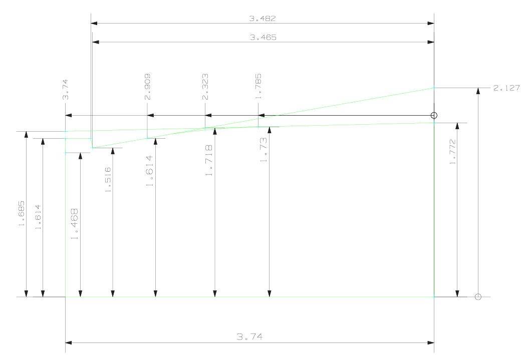
|
|
|
|
[#8]
Quoted: Lol. Of course it would be mm. Sorry I hadn't had my coffee yet. I guess that's pretty much a piece of sheet metal so that changes things a bit. Unless I hosed something up those should be within a 0.001". I think if you start by laying out those two flat surfaces, there wouldn't be much metal to remove there at the radius. I can just project the lines to the opposite side and give you points there too. That would probably make laying it out easier. I'm still unclear about how it's used. Do you lay the part on there and eyeball it for gaps? ETA: Here's another cut at it. I noticed something was wonky with the radius there, I lost the tangency constraint. Like I said, not a drafter. https://www.AR15.Com/media/mediaFiles/196570/Capture2_JPG-1373506.jpg  Yes, you can see the shape of the pressure plate in the original drawing sitting on the gauge. You just set it on and check for gaps, then bend so there are no gaps. I bought a few top covers and some were jamming the round in the chamber/barrel extension at the wrong angle and this piece is what guides the round after its stripped off the belt. Ill try and make some progress this weekend and see how it turns out. Again thanks for spending some of your time for the help on the template, always amazed at the helpfulness of the gun community. Edit: here is a picture of just the pressure plate  |
|
|
|
[#9]
Okay I see now. If nothing else you could file it to fit one that works.
I have a parts kit I bought for cheap probably 15 years ago I need to put together one of these days. Neat guns. |
|
|
|
[#10]
Quoted: Okay I see now. If nothing else you could file it to fit one that works. I have a parts kit I bought for cheap probably 15 years ago I need to put together one of these days. Neat guns. |
|
|
|
[#11]
This part is good candidate for laser-cutting, and probably wouldnt be too expensive.
|
|
|
 Win a FREE Membership!
Sign up for the ARFCOM weekly newsletter and be entered to win a free ARFCOM membership. One new winner* is announced every week!
You will receive an email every Friday morning featuring the latest chatter from the hottest topics, breaking news surrounding legislation, as well as exclusive deals only available to ARFCOM email subscribers.

AR15.COM is the world's largest firearm community and is a gathering place for firearm enthusiasts of all types.
From hunters and military members, to competition shooters and general firearm enthusiasts, we welcome anyone who values and respects the way of the firearm.

Subscribe to our monthly Newsletter to receive firearm news, product discounts from your favorite Industry Partners, and more.
Copyright © 1996-2024 AR15.COM LLC. All Rights Reserved.
Any use of this content without express written consent is prohibited.
AR15.Com reserves the right to overwrite or replace any affiliate, commercial, or monetizable links, posted by users, with our own.