|
[#1]
|
|
|
|
[#2]
OP. I really admire people like you. One person doing what they can to preserve history.

|
|
|
|
[#3]
Can't wait to see the crawler working again. Thanks for the thread. I like that old stuff. Haven't anything that old. Used to do cylinder head work. So I am familiar with the work involved with what you are doing.
Kroil is the stuff! |
|
|
|
[#4]
Very cool. I'm looking forward to updates.
|
|
|
|
[#5]
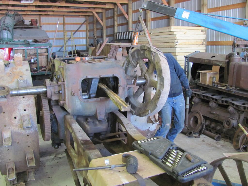
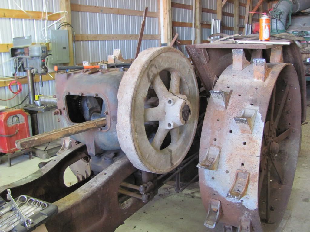
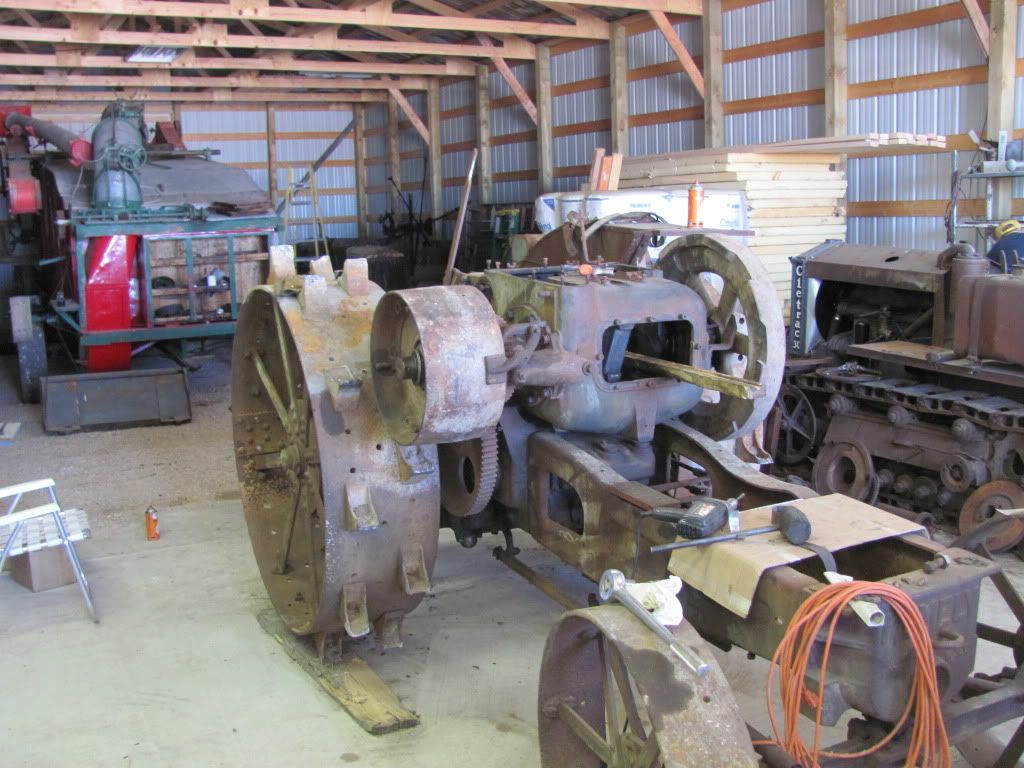
Steadily chugging along on this project. I caught a nice nice day a week ago and took the opportunity to put the flywheel on the one tractor. Dad and I had anticipated this to be at least a half a day project with much hammering and cussing. To my surprise I must have got the crank and bore of the flywheel cleaned up exceptionally well as it only took about 15 min and it just slid right together. When we knocked the wedges out the flywheel clamped onto the crank tight with no key and no clamping bolts. I was a very happy camper.
Most of the rest of the days it has been pretty cold so I loaded up most of the small parts that needed work and brought them all home. I mentioned earlier in the thread making valves. It seemed like as good of time as any to start that. My lathe is a very old (1904 approximately) Southbend. It is worn out but it still functions. You can see in the first picture the old line shaft pulley arrangement still on it. My grandpa modified it to work with an electric motor a long time ago but it still uses the flat belt as the main drive. 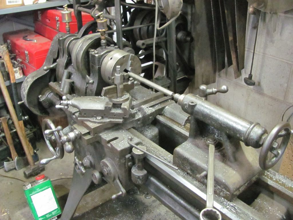
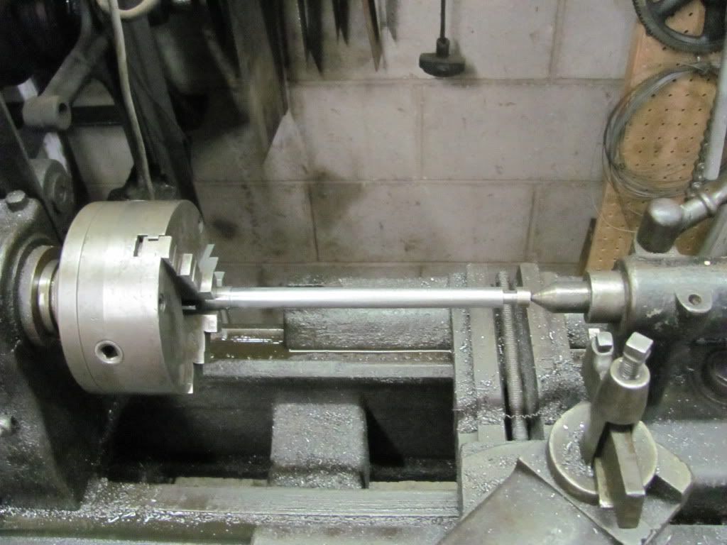
After turning to size and turning in the valve keeper groove they're done for now. The stems are a very odd size. 21/32 give or take a few thousandths. 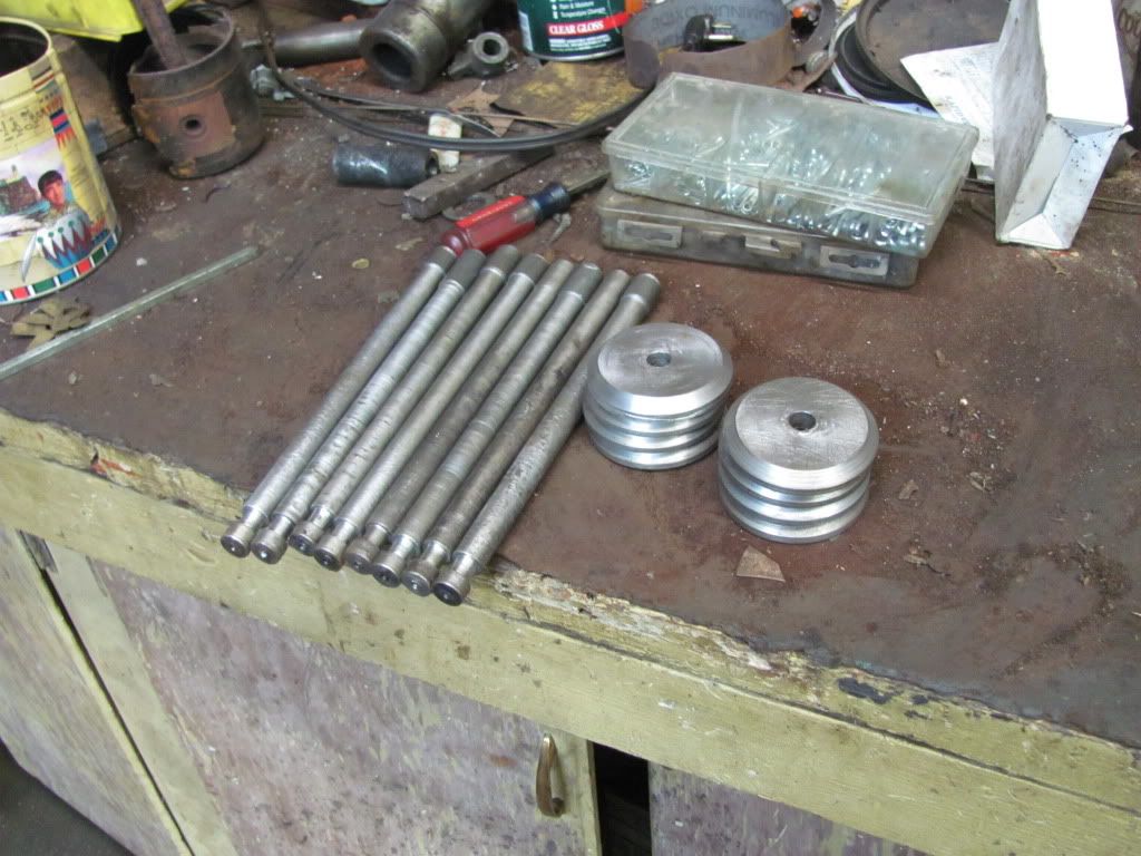
I didn't get any pics when I was making valve heads but it's basically the same setup. My next step with the valves will be to bore the valve head centers to a size, machine a shoulder in the valve stem, and press and weld them together. Once that's done I will use a valve grinder to touch up the valve faces and make everything run true. For reference this is one of my "better" valves. I've been using this one as a pattern. It has a good head but as you can see the stem was severely corroded. I have maybe 2 valves that are salvageable out of 8. So I decided just to make 8 new ones. If I can save an old one great, if not, I'm covered. 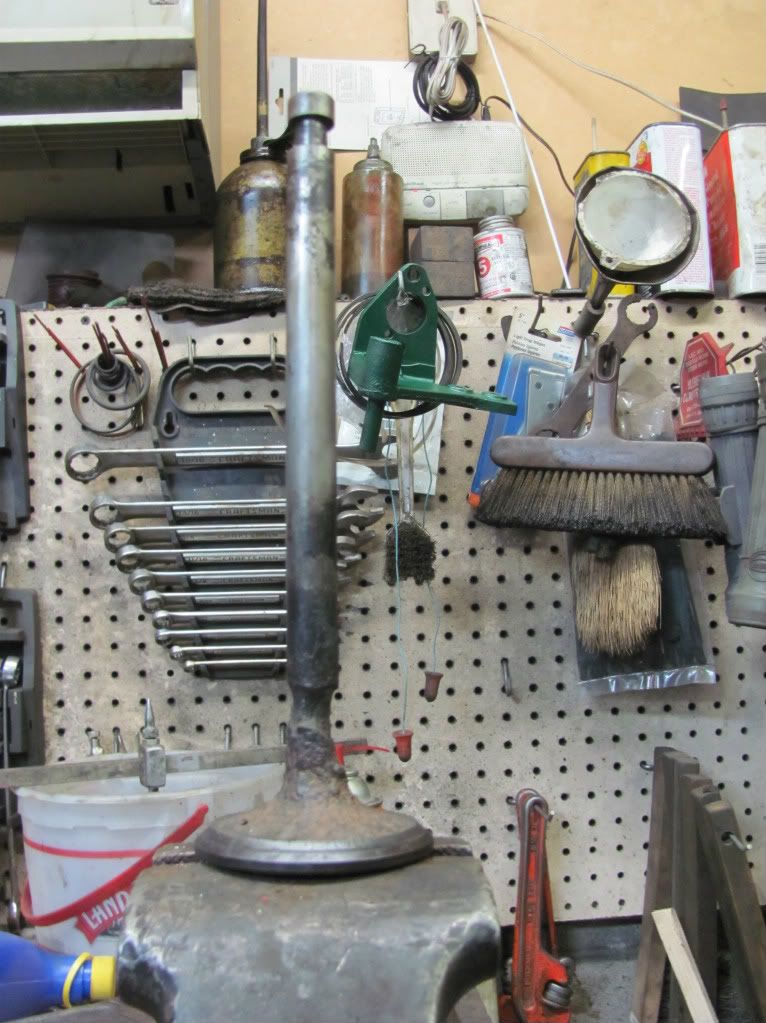
|
|
|
|
[#6]
Nice , very nice .
And also looking forward to seeing the castings being made |
|
|
|
[#7]
Quoted: Nice , very nice . And also looking forward to seeing the castings being made Great thread. Thanks. |
|
|
|
[#8]
Real cool projects, love your old lathe. My grandfather had the same type of lathe, old belt drive converted to electric motor. He taught me how to run it back when I was 11.
Your so lucky for you and your dad to restore the old tractors together. |
|
|
|
[#9]
nice work, and thanks much for posting this. Very interesting as I consider myself handy with the tools, but you sir, take it to another level. Thanks again for taking the time to keep this posted.
|
|
|
|
[#10]
How do you attach the valve heads to the stems? I've seen them attached via friction welding, but it looks like your method will be a press fit over the stem and maybe welding to keep it all together. Very cool project and I look forward to updates.
|
|
|
|
[#11]
Quoted:
How do you attach the valve heads to the stems? I've seen them attached via friction welding, but it looks like your method will be a press fit over the stem and maybe welding to keep it all together. Very cool project and I look forward to updates. I hadn't thought of friction welding. That might be a pretty good idea. I was anticipating doing exactly as you described, press the head and stem together, peen the back side of the stem and weld both sides. I used this method before on smaller engines with good results. I've tried threading the head and stem too but even using the lathe to thread I get a bit of a wobble to the valve and then it takes a lot of grinding to get them true again. |
|
|
|
[#12]
ost
|
|
|
|
[#13]
Quoted:
Quoted:
How do you attach the valve heads to the stems? I've seen them attached via friction welding, but it looks like your method will be a press fit over the stem and maybe welding to keep it all together. Very cool project and I look forward to updates. I hadn't thought of friction welding. That might be a pretty good idea. I was anticipating doing exactly as you described, press the head and stem together, peen the back side of the stem and weld both sides. I used this method before on smaller engines with good results. I've tried threading the head and stem too but even using the lathe to thread I get a bit of a wobble to the valve and then it takes a lot of grinding to get them true again. If I were to design it I would cut a chamfer on the end of the stem, press it in, fill the void with a weld, grind flush and then put a fillet on the other side. The hard part is keeping it perpendicular. That will take a simple fixture or maybe you could tac weld the backside with braces and weld the front, then the back Lots of ways to go. Have fun. |
|
|
|
[#14]
Awesome project.
|
|
|
|
[#15]
Quoted:
Real cool projects, love your old lathe. My grandfather had the same type of lathe, old belt drive converted to electric motor. He taught me how to run it back when I was 11. Your so lucky for you and your dad to restore the old tractors together. I really do realize just how lucky I am to be able to do this with my Dad. I'm not saying we don't have our fights but I would say my relationship with him is very strong and I owe a lot of that to this type of thing. Even last night my sister in law made Dad a picture book of all our tractors with the stories about them for Christmas. We all talked and laughed for a couple hours about some of the stuff that has happened over the years with our tractors. And a lot of it we'd kinda forgot about. Some of it we didn't even know we had pictures of. Well on to the update. My brother was around yesterday morning and he's far more experienced with casting than I am so we decided to make a couple little parts. We don't have to ability to make cast iron parts at this time. The furnace simply won't get the material hot enough. We're working on that. So all parts we make right now are aluminum. This is fine for parts that aren't high stress and will be painted. The parts shown are just clutch linkage clevises. Because I already had a couple parts I can use the originals as a pattern. If I didn't have an original I would have to make a wooden pattern. These parts are pretty small so shrinkage isn't much of a concern but you have to keep in mind when casting that there is a shrinkage factor. For cast iron the rule of thumb is about 1/4" per foot in all directions. Aluminum is a bit higher. So if you're making patterns, especially larger ones, you need to increase the size of your pattern to account for it. These are simple sand castings. First we fill half of the box with casting sand. Casting sand is very fine and this stuff uses oil as a binder so there is no loss. After a casting is finished the sand is charred and doesn't hold shape anymore but we at oil to it again to bring it back. We put part about halfway below the top of the sand and pack the sand good and tight around it. Then we sprinkle baby powder over the sand and the part. The baby powder keeps the sand from sticking together. When we put the top half of the box on and fill and pack it, the baby powder allows the boxes to separate. When the sand is packed we use a tube to make a hole for the material to run in. This shaft is called a sprue. Then we separate the halves and carefully remove the pattern so as not to disturb the sand. This part is a little tricky and we were having some difficulty with it. Once the pattern is out we dig out a runner shaft between the negative cavity of the part and the sprue shaft. The halves are placed back together and it's ready to pour. 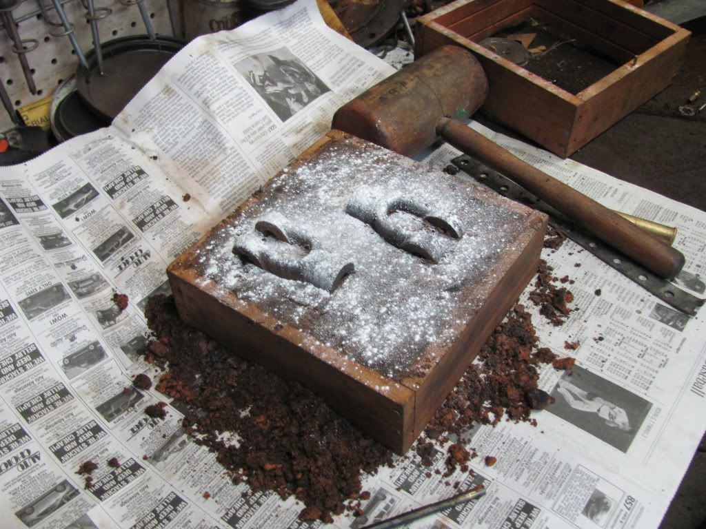
Here you get an idea of what I was describing above. 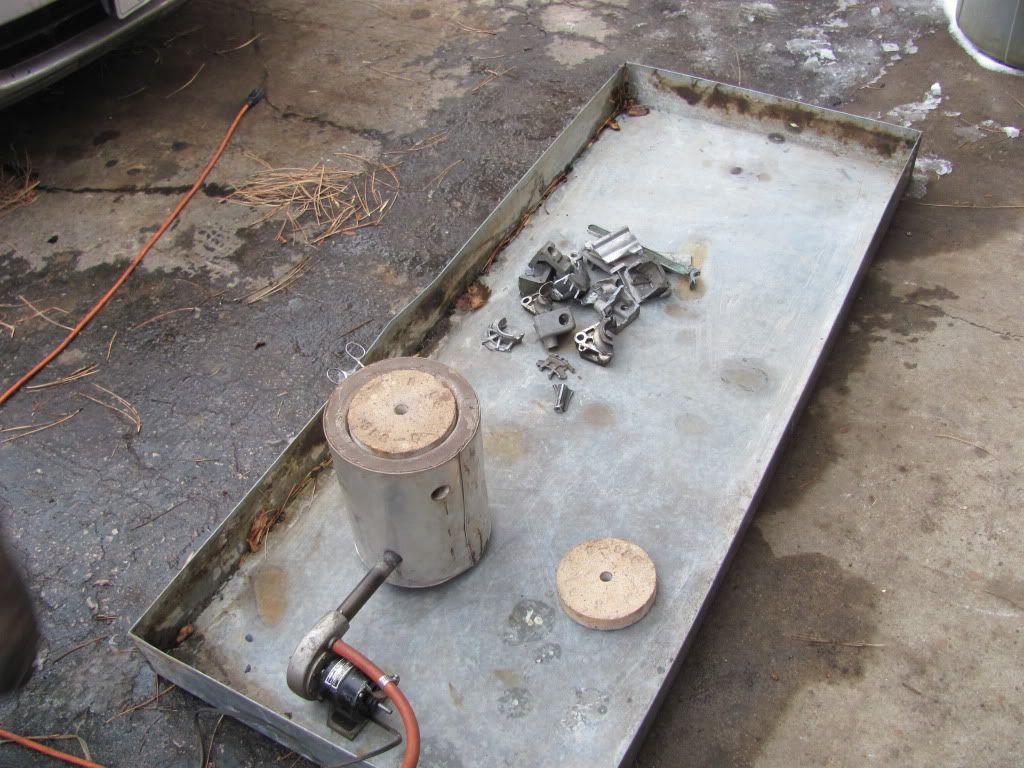
The furnace we are using is pretty small. We have 3 different furnaces and different crucibles. This is the smallest for small parts like this. It's more efficient with the propane. You can also see the pile of scrap aluminum we'll use to make these parts. 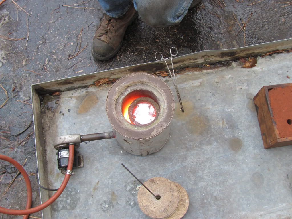
After filling the crucible. 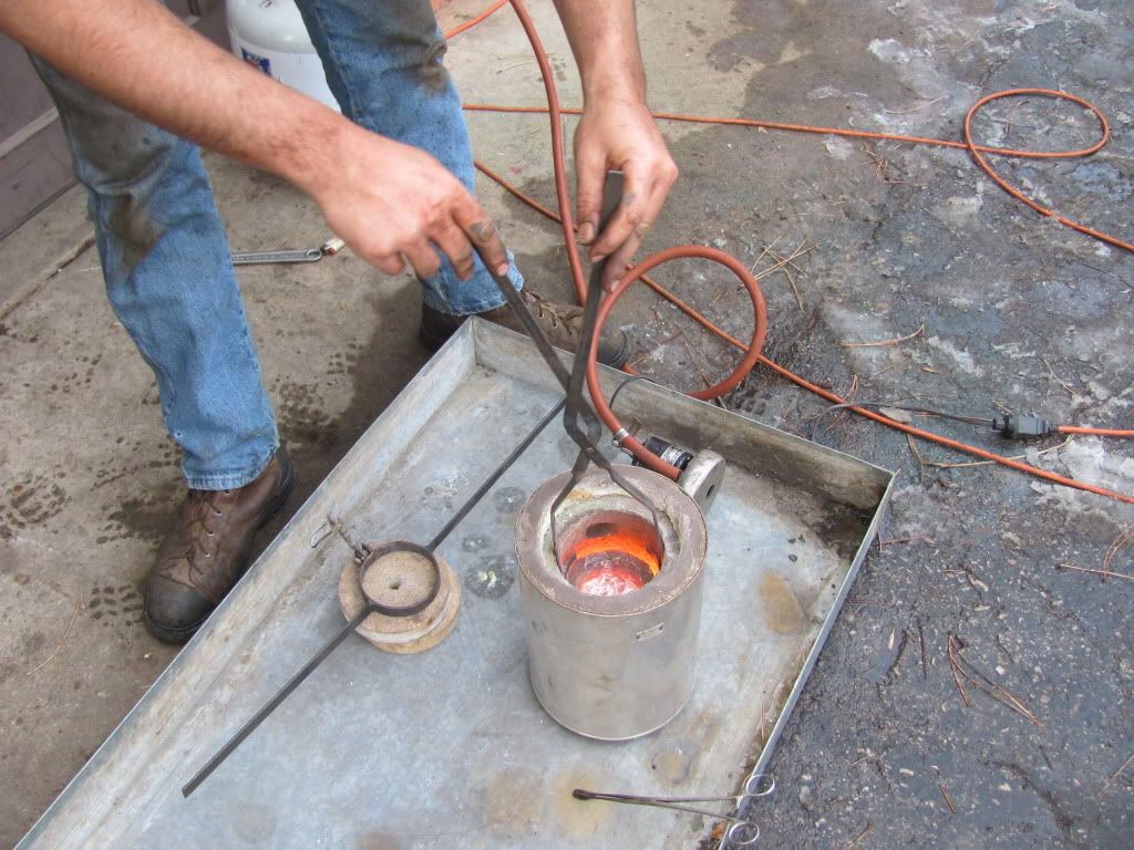
Removing the crucible from the furnace with tongs. My brother is an idiot sometimes. I would highly recommend wearing gloves and a face shield. 
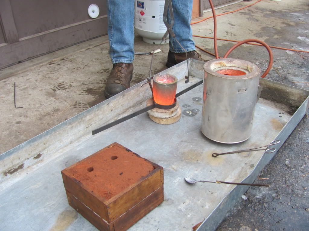
Placing the crucible in the carrier 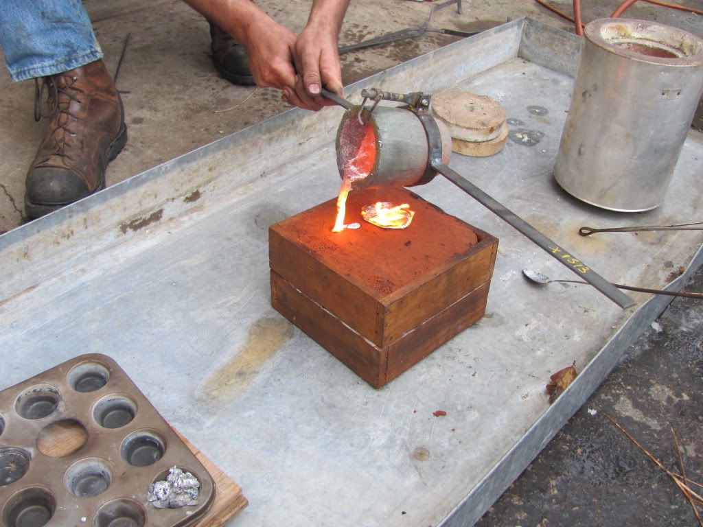
Pouring the material into the mold. 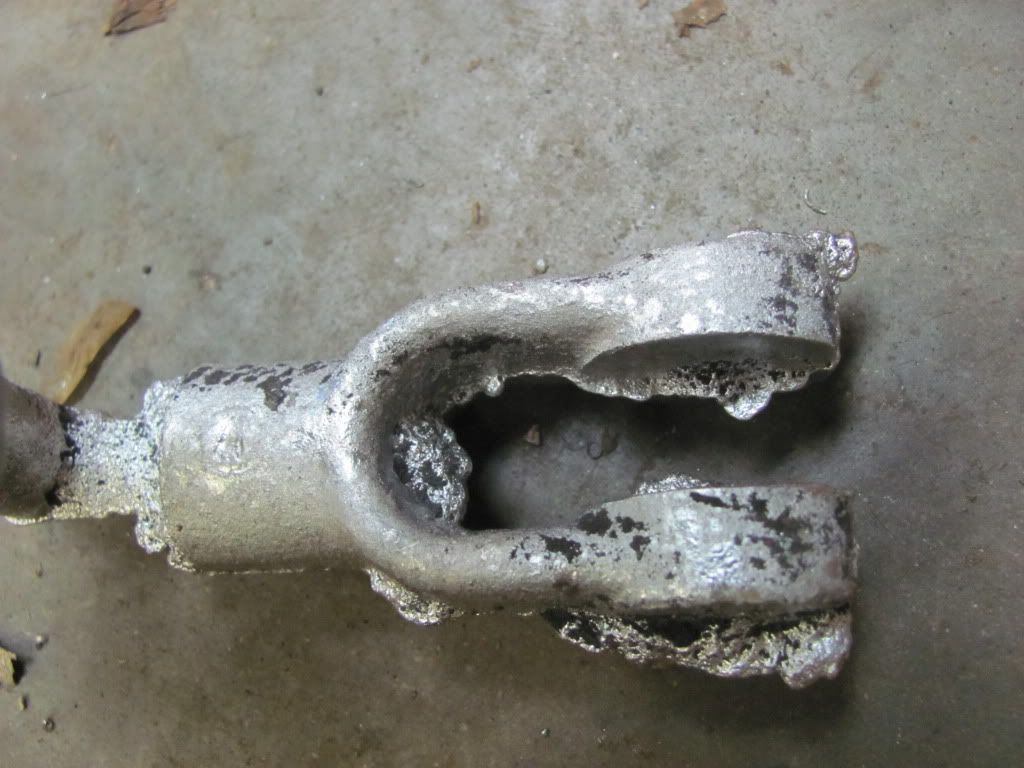
After letting everything cool for a couple hours we knock the mold apart and take out the raw castings. You can see some of the detail you you can get from these castings. Notice the circle with the A stamped in the middle. This was on the original part. It was done after casting at the factory but we were able to get it into the reproduction casting. 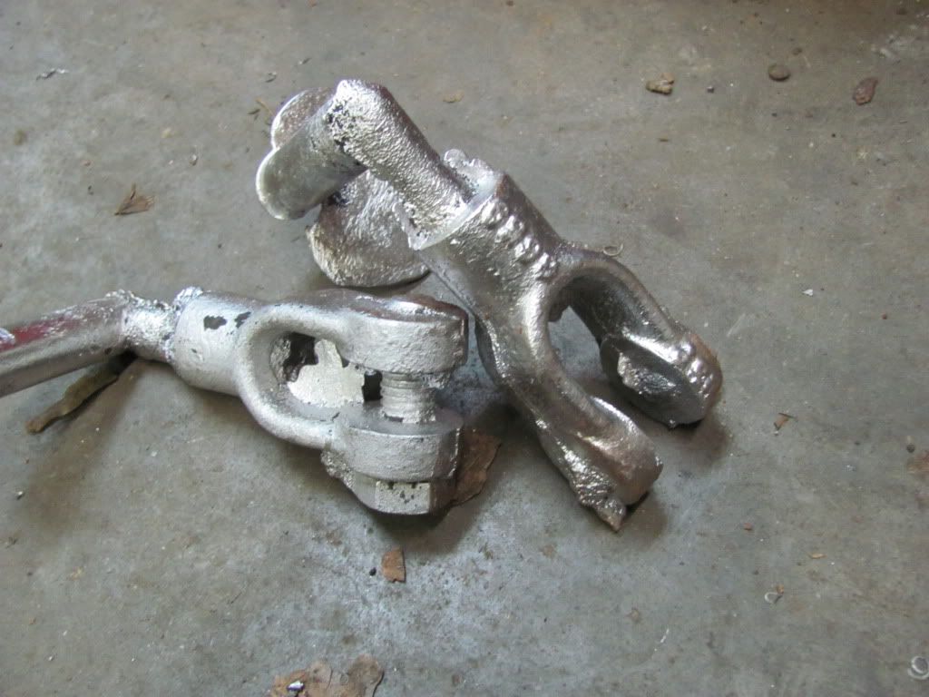
And the casting numbers on the other side. You can see the bolt that was placed in the one clevis. This was to aid releasing it from the mold. This particular one was giving us trouble and this fixed it. I'll simply cut the head and threads off the casting when I finish. The final step, which I haven't done yet is to clean up the castings. I'll cut the runner and sprue off and drill and tap that end of the clevis. A quick grinder job on the flashing around the outside of the parts will take care of that extra material. I'll also hit it with a course wire wheel to blend some of the grinder marks back into the casting. Finally, I'll drill a hold through the clevis and paint the parts. Then they're done. These obviously aren't terribly professional but they work. And it's a lot cheaper than finding originals or having an outside foundry do it. Once on the tractor nobody will know the difference. |
|
|
|
[#16]
This thread is absolutely outstanding. Merry Christmas, btw.
|
|
|
|
[#17]
One of the coolest threads on ARFCOM ever.
|
|
|
|
[#18]
Quoted:
One of the coolest threads on ARFCOM ever. This. But the photos are shut off! |
|
|
|
[#19]
Quoted:
Quoted:
One of the coolest threads on ARFCOM ever. This. But the photos are shut off! Yeah I just got the email saying bandwidth exceeded and it'll reset on the 4th. If you're interested the pics are here. I think you can go to my album directly. http://s641.photobucket.com/albums/uu140/likesoldiron/25-40%20Rumely/ |
|
|
|
[#20]
Quoted: One of the coolest threads on ARFCOM ever. Absofrinkinlutely. You the man. |
|
|
|
[#21]
i like it
|
|
|
|
[#22]
TAG
TRG |
|
|
|
[#23]
This thread is awesome.
|
|
|
|
[#24]
Been playing around in the shop some more. I did the valve seats on the head from humpty dumpty. They were in pretty tough shape and I wasn't sure if they'd clean up. They turned out ok I think. Not great, but useable. I have a valve seat grinder for doing this. It looks kind of like an old black and decker drill with an octagon head on it. That matches up to a stone holder and a stone. Surprisingly you can still buy stones new from Goodson.
This kind of gives you the idea. 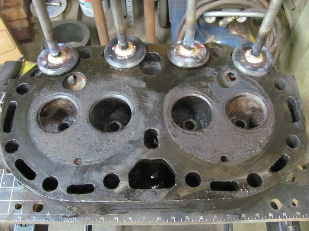
Before starting. 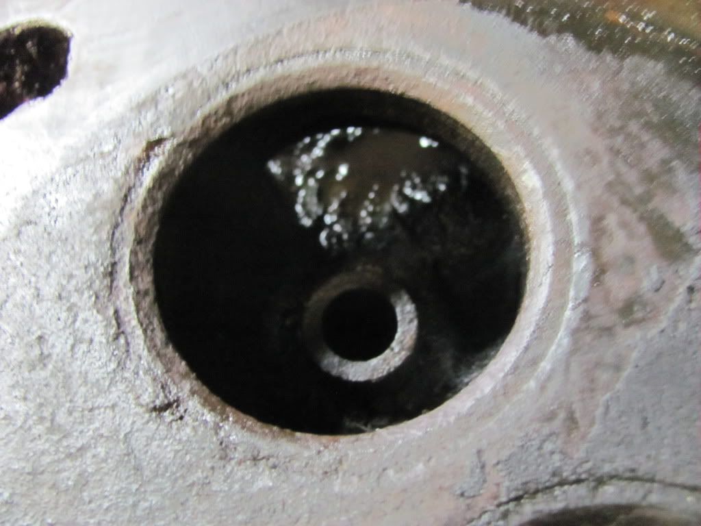
Close up of one of the seats. You can see it's awfully rough. 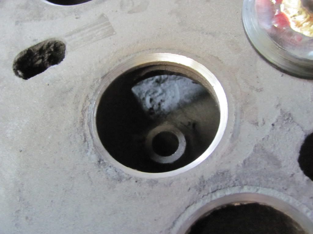
The same seat after a little bit of grinding. I did a little more after the pic was taken. You can see the thin shiny part needs some more work. 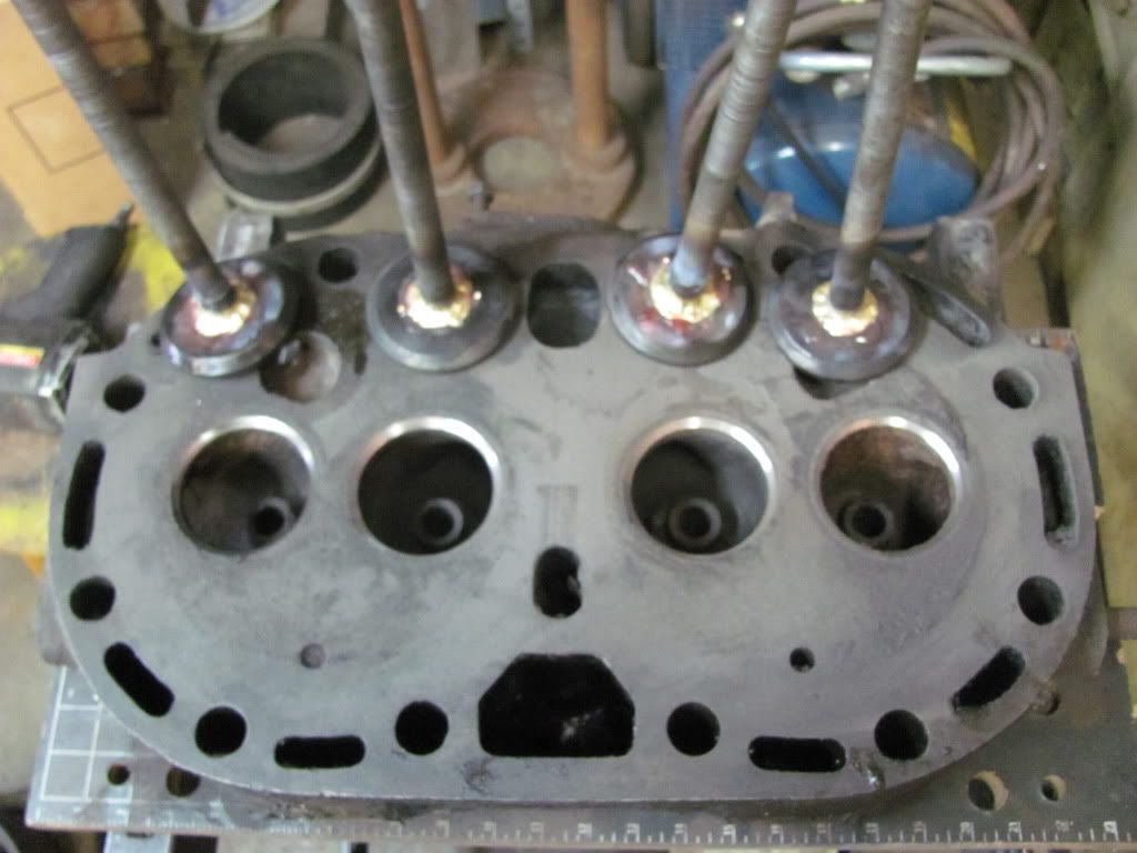
All cleaned up. 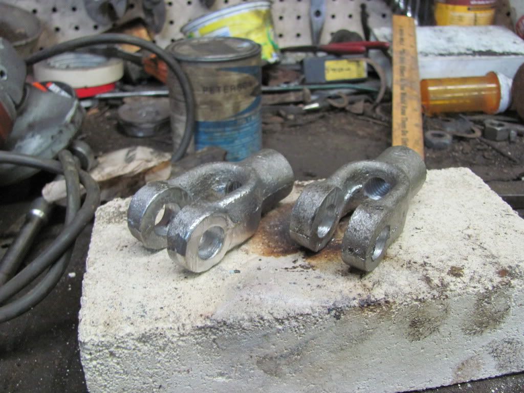
Finished those castings I did the pics of earlier in the thread. 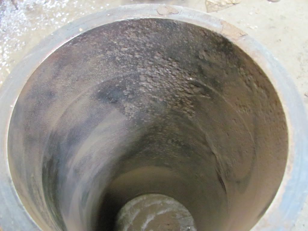
And shit just got expensive, again. I cleaned up one of the sleeves getting ready to hone it and found this under the grease. The ring you see in the cylinder is the top of the stroke for the piston. It's also where the bore needs to be the best to develop compression. This just isn't going to fly. I'm going to need to make a couple phone calls and see if I can't get this bored and sleeved back. I would be very surprised if the price tag for this comes in anything less than $600-700. |
|
|
|
[#25]
Looks like fun and a project
|
|
|
|
[#26]
Quoted:
I bought 2 of these tractors a few weeks ago. The first one made it home on Monday night. I started cleaning it yesterday and tore into it today. I got it in pieces like this. It is a Rumely Oilpull model 25-40 X. This one was made in 1928. 25 stands for the advertised HP on the drawbar and 40 is the advertised HP on the belt. In the Nebraska tractor tests this model actually made close to 40hp on the drawbar and 50 on the belt. Rumely used the Oilpull moniker because the tractors used oil in the cooling system rather than water. Back in the day kerosene was much cheaper than gas but for the tractor to burn it, it had to run hot. The oil allowed the tractor to run hotter and burn the kerosene better. Various odds and ends to make it go. There are a few parts here for the other "erector set" thats coming. I will post pics of it when it gets here. http://i641.photobucket.com/albums/uu140/likesoldiron/25-40%20Rumely/IMG_0595.jpg http://i641.photobucket.com/albums/uu140/likesoldiron/25-40%20Rumely/IMG_0596.jpg After a good power washing to remove some of the 80 year old dirt and grease. http://i641.photobucket.com/albums/uu140/likesoldiron/25-40%20Rumely/IMG_0598.jpg http://i641.photobucket.com/albums/uu140/likesoldiron/25-40%20Rumely/IMG_0601.jpg http://i641.photobucket.com/albums/uu140/likesoldiron/25-40%20Rumely/IMG_0603.jpg Fuel tank needs some help. http://i641.photobucket.com/albums/uu140/likesoldiron/25-40%20Rumely/IMG_0608.jpg After an hour and a half by myself pushing the thing in the shop and the rest of the day tinkering this is what it looks like. http://i641.photobucket.com/albums/uu140/likesoldiron/25-40%20Rumely/IMG_0615.jpg http://i641.photobucket.com/albums/uu140/likesoldiron/25-40%20Rumely/IMG_0619.jpg Customary bullet holes in the exhaust stack. http://i641.photobucket.com/albums/uu140/likesoldiron/25-40%20Rumely/IMG_0617.jpg My first fuckup on this project. This is the fuel pump shaft. Note to self, do not remove cam tower before removing fuel pump shaft or you'll bend it. http://i641.photobucket.com/albums/uu140/likesoldiron/25-40%20Rumely/IMG_0621.jpg So here's my progress for today. I removed the governor, cam tower, lubricator, oil lines, right fender, and a few little odds and ends. The cam was stuck but I got that freed up. The lifters and rollers were also stuck (yeah they had roller lifters in 1928) and I got that fixed. Once I got the cam loose I figured out the magneto drive was also stuck but I got it freed up too. The lubricator was borderline stuck but some Kroil and a little working back and forth and she's pumping now near as I can tell. I got the governor freed up as well but need to do more. It's still very stiff. I also got the transmission shifting mechanism working better too. All that I know of that's stuck now is the oil pump for the cooling system. I have a lot of work ahead of me yet. The mechanical beauty and complexity of those older machines never ceases to amaze me. Those old designs are ingenuity we'll likely never see again in our lifetimes. Born of an age when people took pride in what they did, who they were, and what they made. |
|
|
|
[#27]
Love seeing old stuff like this brought back to life....just my $0.02, but I would do a full restoration on it.
|
|
|
|
[#28]
Quoted:
The mechanical beauty and complexity of those older machines never ceases to amaze me. Those old designs are ingenuity we'll likely never see again in our lifetimes. Born of an age when people took pride in what they did, who they were, and what they made. I think you understand why I have such a passion for this stuff now. |
|
|
|
[#29]
Awesome thread!
Am I the only one that saw a face in this piece? 
|
|
|
|
[#30]
Very cool!! Love to see the old stuff brought back to life! Been going to the Steam-Up here in Brooks Oregon since I was a kid, it is definitely one of the high points of the year.
What is the largest Stationary Engine you guys have? How about some pics of them, too? TriumphRider |
|
|
|
[#31]
Quoted:
Awesome thread! Am I the only one that saw a face in this piece? http://img.photobucket.com/albums/v458/APSU/Screenshot2012-01-12at42426PM.png I lol'd. Quoted:
Very cool!! Love to see the old stuff brought back to life! Been going to the Steam-Up here in Brooks Oregon since I was a kid, it is definitely one of the high points of the year. What is the largest Stationary Engine you guys have? How about some pics of them, too? TriumphRider The 3 biggest in order are: Enterprise 1041hp DSG-36. My brothers new toy. Fairbanks Morse 50hp YV Fairbanks Morse 25hp Y-HB From there its pretty much 10hp and below. Also have a couple stationary steam engines that aren't operational right now. One is an American Blower vertical and I can't remember what the other is but it's a 3cyl vertical monster. Each jug is a couple feet in outside diameter. I can only snag a pic of the Enterprise. Don't have digital pics of the rest. http://www.smokstak.com/forum/attachment.php?attachmentid=122024&d=1322518984 |
|
|
|
[#32]
Haven't really done much worthy of taking pics of for a while. Lots of little stuff. I've been working on magnetos and currently have 5 torn apart swapping pieces back and forth and rebuilding them. I patched up my oil bath for the intermediate gear between the crank and the transmission.
Here is what I started with. It's pretty shitty. 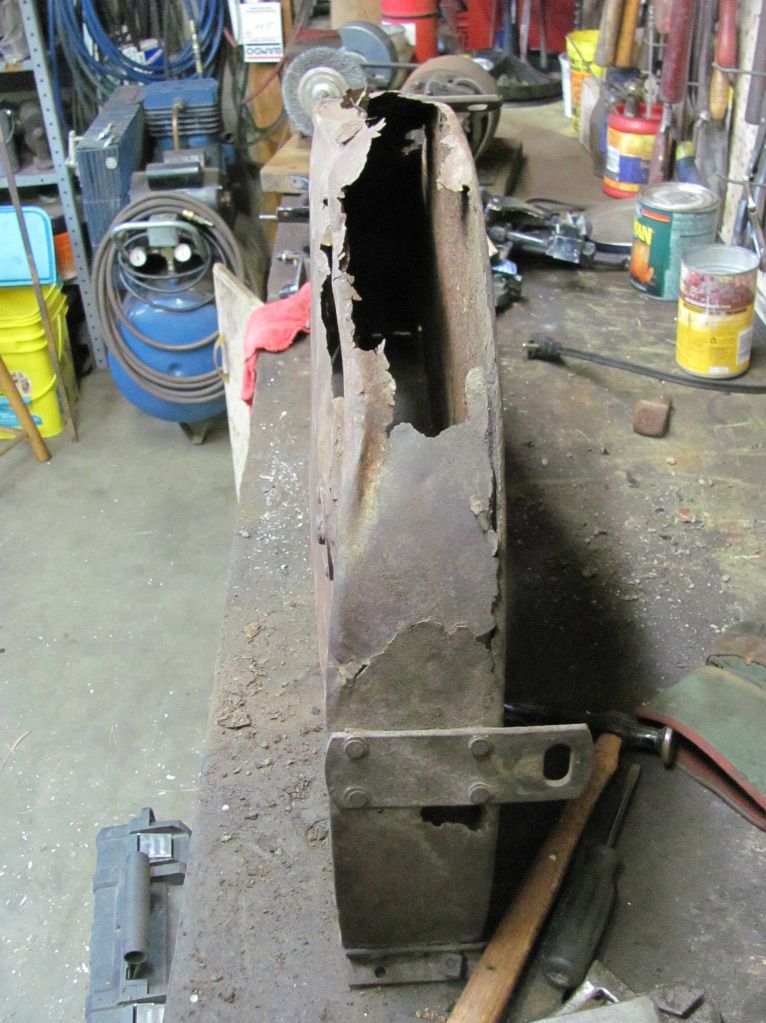
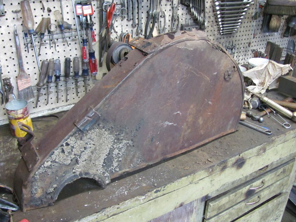
I debated making an entirely new guard but I don't have any sheet metal tools. So I decided I'd cut out the nasty part, leave the interlocked sheetmetal edge, and patch what I needed back in. You can see one of the the replacement sections below. 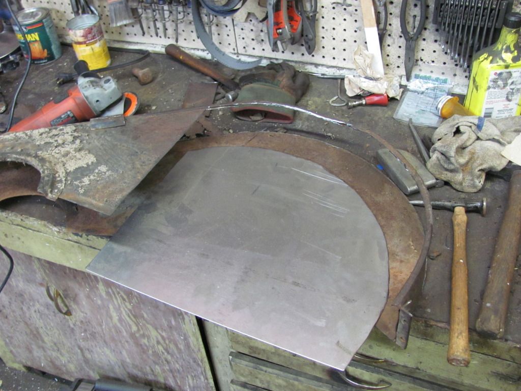
Tacked it in place. Have I mentioned yet how bad I need a small mig or better yet a TIG welder? 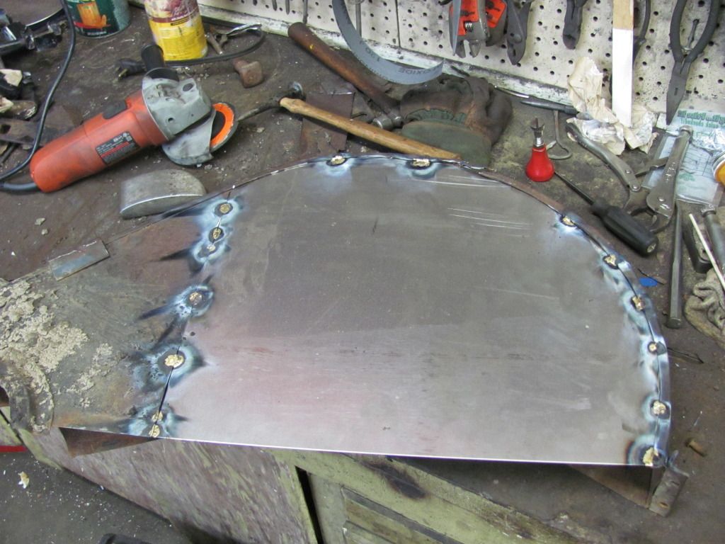
And the more or less finished product. Still needs some grinding and it's gonna need some filler work but I think it came out ok. Not great, but passable. You can see I hot riveted the drain back in as well while it was easy to get at. I still need to hot rivet the mounting brackets back on but I'm going to wait and test fit everything to the tractor first so I don't wind up having to grind them off and do it again. 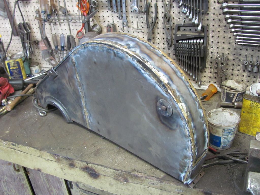
Also have rebuilt the governor assemblies with new bearings, bushings, pins if necessary, etc. Here's one apart. The flyweights on the lower left, fly apart as engine speed increases (driven by the crankshaft), as they do they push on a T-bracket which slides on the shaft, which in turn pushes a floating thrust bearing and dog against the governor forks seen in the middle, which actuates the shaft that's connected to the governor arm shown on the top, which is connected to a spring and throttle lever mounted to the governor housing, and a linkage back to the carb that actuates a butterfly. More spring pressure through the throttle, more RPM. Got that? Neither did Rumely. These were the weakest link in nearly every Rumely ever built and have caused quite a few catastrophic failures at the hands of an inexperienced operator. If you catch it running away it's as simple as turning off the fuel at the carb. The engine will quit running almost immediately. But when panic mode sets in, stuff hits the fan. Typically, "stuff" is the rod. 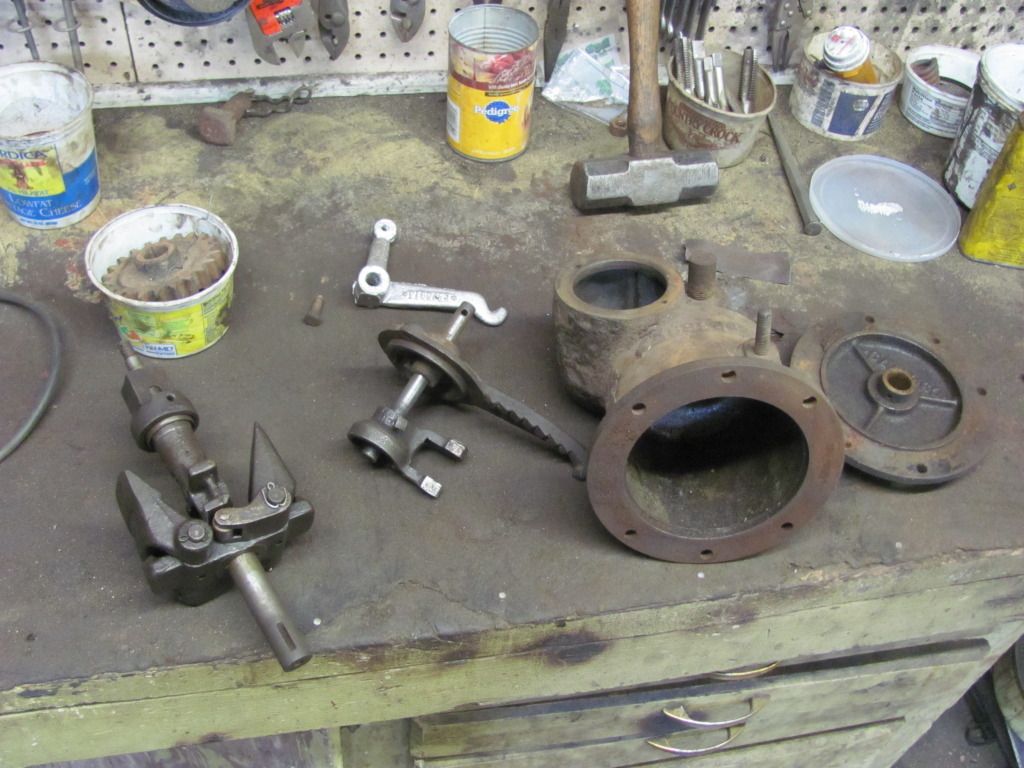
Here is one put together. 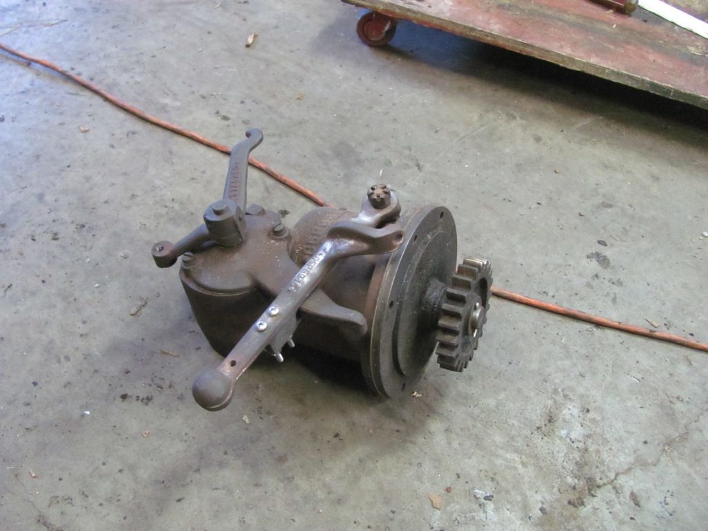
|
|
|
|
[#33]
Quoted: <–––––––––––– Could have welded it for youHaven't really done much worthy of taking pics of for a while. Lots of little stuff. I've been working on magnetos and currently have 5 torn apart swapping pieces back and forth and rebuilding them. I patched up my oil bath for the intermediate gear between the crank and the transmission. Here is what I started with. It's pretty shitty. http://i641.photobucket.com/albums/uu140/likesoldiron/25-40%20Rumely/IMG_0780.jpg http://i641.photobucket.com/albums/uu140/likesoldiron/25-40%20Rumely/IMG_0781.jpg I debated making an entirely new guard but I don't have any sheet metal tools. So I decided I'd cut out the nasty part, leave the interlocked sheetmetal edge, and patch what I needed back in. You can see one of the the replacement sections below. http://i641.photobucket.com/albums/uu140/likesoldiron/25-40%20Rumely/IMG_0782.jpg Tacked it in place. Have I mentioned yet how bad I need a small mig or better yet a TIG welder? http://i641.photobucket.com/albums/uu140/likesoldiron/25-40%20Rumely/IMG_0783.jpg And the more or less finished product. Still needs some grinding and it's gonna need some filler work but I think it came out ok. Not great, but passable. You can see I hot riveted the drain back in as well while it was easy to get at. I still need to hot rivet the mounting brackets back on but I'm going to wait and test fit everything to the tractor first so I don't wind up having to grind them off and do it again. http://i641.photobucket.com/albums/uu140/likesoldiron/25-40%20Rumely/IMG_0784.jpg Also have rebuilt the governor assemblies with new bearings, bushings, pins if necessary, etc. Here's one apart. The flyweights on the lower left, fly apart as engine speed increases (driven by the crankshaft), as they do they push on a T-bracket which slides on the shaft, which in turn pushes a floating thrust bearing and dog against the governor forks seen in the middle, which actuates the shaft that's connected to the governor arm shown on the top, which is connected to a spring and throttle lever mounted to the governor housing, and a linkage back to the carb that actuates a butterfly. More spring pressure through the throttle, more RPM. Got that? Neither did Rumely. These were the weakest link in nearly every Rumely ever built and have caused quite a few catastrophic failures at the hands of an inexperienced operator. If you catch it running away it's as simple as turning off the fuel at the carb. The engine will quit running almost immediately. But when panic mode sets in, stuff hits the fan. Typically, "stuff" is the rod. http://i641.photobucket.com/albums/uu140/likesoldiron/25-40%20Rumely/IMG_0786.jpg Here is one put together. http://i641.photobucket.com/albums/uu140/likesoldiron/25-40%20Rumely/IMG_0787.jpg ETA: Very awesome work there CK
|
|
|
|
[#34]
|
|
|
|
[#35]
This thread continues to deliver.
|
|
|
|
[#36]
You, sir, are amazing.
I thought I was hot shit for knowing my way around a car. |
|
|
|
[#37]
Quoted:
You, sir, are amazing. I thought I was hot shit for knowing my way around a car. The principles are pretty much the same. The execution though, that can get a little tricky. There are a lot of times I'm left scratching my head going, "how in the name of everything that's holy, did they do this and expect it to work." But if you can work on a car, you can restore a tractor. |
|
|
|
[#38]
Quoted: Quoted: You, sir, are amazing. I thought I was hot shit for knowing my way around a car. The principles are pretty much the same. The execution though, that can get a little tricky. There are a lot of times I'm left scratching my head going, "how in the name of everything that's holy, did they do this and expect it to work." But if you can work on a car, you can restore a tractor. Well sure, but when I want a new cam I order one from summit or jegs... I don't heat up the furnace and forge one in my backyard. |
|
|
|
[#39]
It was Christmas at the house today. My new piston rings showed up. So that lit a fire under my butt to get some more stuff done. Tomorrow after running a 5k in the morning I'm going to go like hell putting one of the Rumely's together. I'm still missing an internal part for the humpty dumpty one so it has to wait for a bit yet.
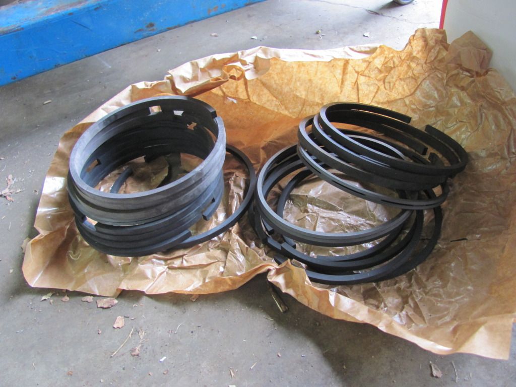
I got rings in 2 different widths because of ring groove wear. I put the pistons in the lathe and squared up the grooves and fitted the rings appropriately. 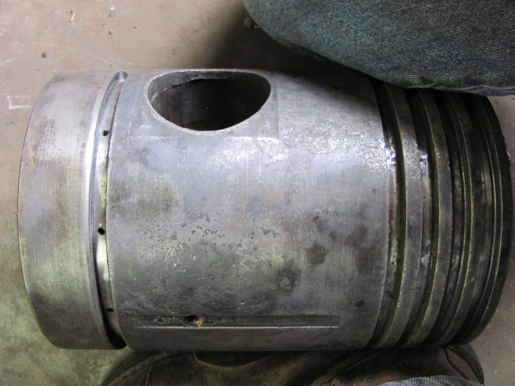
I also decided to convert the last ring groove to an oil ring and drilled a series of holes in the groove. The original design used scraper rings to scrape excess oil back off the cylinder wall. It worked like crap and the tractors were sometimes known as "Oil Pukes" because that excess oil then got blown out the exhaust and most likely covering the operator. The oil rings help this a ton. 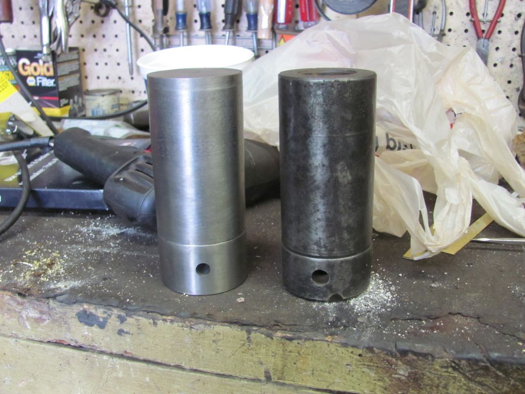
I was also short a wrist pin so I turned one out on the lathe. I was pretty happy with the fit all said and done. I didn't know how close the old worn out lathe could get but it turned out pretty good. 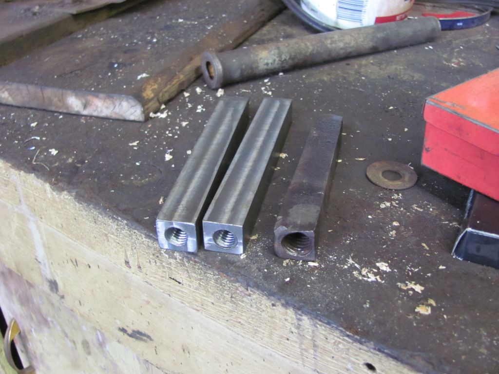
Also had to make new keys for the flywheels. I had an original but it was a bit worn and the threads for removing it if necessary had been stripped. Only problem was the key is 13/16 by 3/4. Can't buy such a key. So I bought 13/16 stock and milled off a face then drilled and tapped the holes. 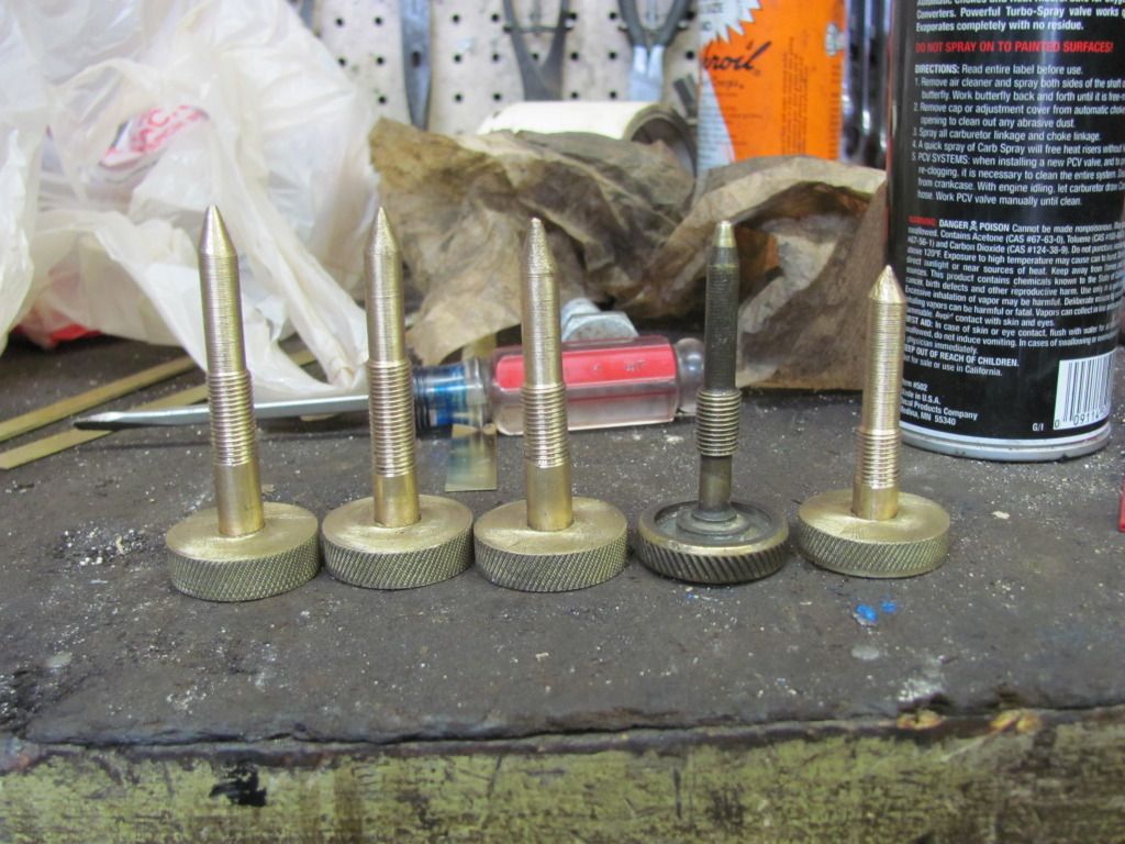
And finally I needed to make new needle valves. I didn't have any but my dad has the next size smaller tractor to this one and the needle valves are identical so I used his as a pattern. The needle valve has 2 functions. It is a fuel shut off and a jet. You open or close it as necessary to get the proper amount of fuel so it doesn't run too rich or too lean depending on elevation and load. And you adjust it pretty often while operating the tractor. The tractor used 2 on each carb. One was for fuel the other water. When burning kerosene back in the day you needed to add water to the kerosene to keep the fuel from detonating. Well I'll never run kerosene, only aviation gas (for various reasons none of them performance). So 2 of these valves will never be used (shorty on the right). They're simply there for looks. The only thing I'm waiting on now to make one tractor run is valve spring retainers and valve keepers. I've got them ordered. If they got here soon I could have one tractor running in about 3 days. I've also dropped the sleeve shown earlier with the serious pitting off at a guy who is going to bore and sleeve it for me. He also has a 25-40 Rumely like this one so we talked about the various bits and pieces of them. I did learn I got a screaming deal on my piston rings. I paid $400 for all of mine, both tractors. He paid $700 for 1 tractor. I was kinda happy I got such a good deal, felt bad he paid so much though. |
|
|
|
[#40]
AWESOME man truly awesome
|
|
|
|
[#41]
Wow. Looks like a lot of work is ahead of you.
|
|
|
|
[#42]
I like this thread!
|
|
|
|
[#43]
This is a tag.
|
|
|
|
[#44]
Wow, just wow!
|
|
|
|
[#45]
in on two
|
|
|
|
[#46]
tag. Impressive work, dude.
|
|
|
|
[#47]
I love these old machines. I just wish I had time to fix one up.
|
|
|
|
[#48]
Tag for cool old toys and people that know how to fix them.
|
|
|
|
[#49]
Do you use them much when they're restored, or just fire them up for fun?
They're gorgeous machines, and you're a whiz at them! |
|
|
|
[#50]
I'm glad I saw this thread now. I did a little aluminum casting in a manufacturing class in high school, but none of my stuff came out as nice as yours. I greatly admire you and other people who are able to do what you are doing with your tractors. It's amazing.
|
|
|
 Win a FREE Membership!
Sign up for the ARFCOM weekly newsletter and be entered to win a free ARFCOM membership. One new winner* is announced every week!
You will receive an email every Friday morning featuring the latest chatter from the hottest topics, breaking news surrounding legislation, as well as exclusive deals only available to ARFCOM email subscribers.

AR15.COM is the world's largest firearm community and is a gathering place for firearm enthusiasts of all types.
From hunters and military members, to competition shooters and general firearm enthusiasts, we welcome anyone who values and respects the way of the firearm.

Subscribe to our monthly Newsletter to receive firearm news, product discounts from your favorite Industry Partners, and more.
Copyright © 1996-2024 AR15.COM LLC. All Rights Reserved.
Any use of this content without express written consent is prohibited.
AR15.Com reserves the right to overwrite or replace any affiliate, commercial, or monetizable links, posted by users, with our own.