|
[#1]
That happened to me starting out. Look up leveling the bed with a post it note. That has worked flawlessly for me. |
|
|
|
[#2]
Quoted: Now just need to finish assembling the rear sight (thanks @Overkill777) and then shoot it! https://i.imgur.com/pJFu1sM.jpg https://i.imgur.com/gQntpL7.jpg https://i.imgur.com/uELHvi5.jpg awsome |
|
|
|
[#3]
for anyone contemplating doing this build. some thoughts having completed it to able to cycle via the charging handle but not yet fired.
first off, the guide and distro is super easy for anyone esp a novice to follow along. i built the frame at .2mm based on default cura settings. wish i had done .12 and am reprinting at .12 now. bolts threads came out like shit at .2 and perfect at .12. also the screw threads for me benefitted greatly on the 2nd print from using a raft. Specifically here I am talking about the 4 small bolts and the 1 large bolt. Holes for the lpk fit well and were aligned with each other with no immediate issue. fitment is a bit loose and wiggly compared to an aluminum frame, but perfectly usable. if you look closely at the STL in a cad program you can see that the holes have been made teardrop shaped rather than perfectly round, assumedly for the printers benefit to reduce overhangs. Also the pla+ is not as smooth to turn against at metal so for example turning the safety selector is a bit gritty and sloppy compared to an aluminum frame. also when the takedown pins come out they are all over the place floppy. they do, however retain correctly and the LPK didnt require any adjustment to go it. trigger parts dragged on the walls going in but once installed align and operate well. -less looseness felt here as they are under spring tension.. the buffer block is a big print by itself and i printed it at .12 from the get go - it came out perfect and feels very solid. buffer tube threads fit perfectly with no looseness or gap. alignment is good too. the grip thread has a lot of plasticky grab to it so turning the long grip bolt all the way took a lot of force and felt like the frame would crack at any moment. i said a prayer to the pla gods before each turn and somehow despite all the creaks it made it didn't crack. also the threads were hard to engage initially and it is very easy to cross thread the little pla threads. i am hoping .12 helps this also. alignment with the buffer block and also the front takedown blocks was spot on with no adjustment. alignment to the upper was not good. the print is upside down so the brims and other rough edges at at the top when done while the bottom of the mag well ends up looking like a piece of art. but the upper couldnt mate to the lower correctly and i ended up having to sand the top of the lower to smooth it and bring it down maybe 1/10 of a mm do the upper could mate correctly. It really needs another 1/10.. next time I will use the loose takedown pins on the naked receiver and work on that fitment before installing the lpk, because now I have plastic dust going everywhere. ergonomics are a little off --the buffer support is not directly in the way but my big thumb hits it anyway - i also find i have to rotate around my grip around to push the safety selector because the buffer interface sticks out so far i cant reach over/around it comfortably and still hit enough of the selector with my thumb. that big block of plastic does seem very tough though so I think I wont be editing it at all despite the ergonomic challenges. to try and solve the above and also have a cleaner top from the start i am reprinting the main component upright at .12 to see if i can solve the fitment issue and also tighten up tolerances on some of the looseness. this seems ill advised because of the overhangs and supporting any means supporting all. we'll see if it comes out good or not. Print times.. main body 1 day 8 hrs (at .2) buffer block (at .12) 6 hrs, small parts (I put them all down on the bed at once) - first go at .2, 9 hrs, 2nd go at .12 about 11 hrs. all told about 48 hours of printer time excluding any goof ups. edits for speeling and to add print times |
|
|
|
[#4]
Has anyone used one of these hellfire lowers for a pisol/brace build? I'm assuming that's no different functionally or legally than doing it with a metal lower, right?
|
|
|
|
[#5]
No different. It is your creation so it is what you make it. If you make it a pistol it is a pistol.
|
|
|
|
[#6]
update - printing at .12 did help (a LOT) with threads for the grip screw and also upper / lower fitment.
|
|
|
|
[#7]
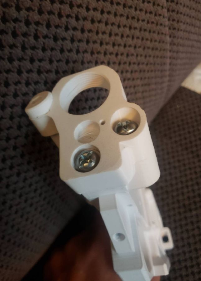
So what is the little horizontal loop just above and aft of the bolt catch pin for?
|
|
|
|
[#8]
Quoted: So what is the little horizontal loop just above and aft of the bolt catch pin for? |
|
|
|
[#9]
Quoted: Are you talking about the horizontal hole right next to where the bolt release lever is located on the hellfire lower? If so, a redditor asked the same thing a while back and the only answer that anyone could come up with is that it's a place to hang whatever you want, like how drift cars have charms or stuffed animals hanging from their rear bumper. Quoted: Quoted: So what is the little horizontal loop just above and aft of the bolt catch pin for? gawd I hope not.  I was thinking since the plastic doesnt conform and hold the roll pin for the bolt catch it was a place to add a small set screw to prevent the roll pin from falling out. |
|
|
|
[#10]
Nope, designer put it there to hold a charm.

|
|
|
|
[#11]
Quoted: gawd I hope not. I was thinking since the plastic doesnt conform and hold the roll pin for the bolt catch it was a place to add a small set screw to prevent the roll pin from falling out. Quoted: Quoted: Quoted: So what is the little horizontal loop just above and aft of the bolt catch pin for? gawd I hope not. I was thinking since the plastic doesnt conform and hold the roll pin for the bolt catch it was a place to add a small set screw to prevent the roll pin from falling out. That's what I came up with. The pin hole is a blind hole so you can't push it back out unless you drill it through first. I thought it was for some kind of pin retention but hanging a "charm" that close to a working part doesn't sound like good engineering practice. |
|
|
|
[#12]
Quoted: Nope, designer put it there to hold a charm. This is correct. Stupid on the designer's part, but correct. |
|
|
|
[#13]
Quoted: That's what I came up with. The pin hole is a blind hole so you can't push it back out unless you drill it through first. I thought it was for some kind of pin retention but hanging a "charm" that close to a working part doesn't sound like good engineering practice. Quoted: Quoted: Quoted: Quoted: So what is the little horizontal loop just above and aft of the bolt catch pin for? gawd I hope not. I was thinking since the plastic doesnt conform and hold the roll pin for the bolt catch it was a place to add a small set screw to prevent the roll pin from falling out. That's what I came up with. The pin hole is a blind hole so you can't push it back out unless you drill it through first. I thought it was for some kind of pin retention but hanging a "charm" that close to a working part doesn't sound like good engineering practice. its an awkward angle to drill also - if you are lucky you can hit the roll pin and the drill will push it out - otherwise keep drilling till you do, lol. guess I have to 3d print a charm now.. adding that to the print time in the other thread tho. |
|
|
|
[#14]
Have any of you guys seen the Hoffman Tactical lower? This redditor cleaned it up a bit and made some changes, including a channel for the anti-walk pins. I think I like the look of this a lot better than the hellfire, and according to the comments one could add that buffer plate stabilizer to both sides for extra strength if running a slick-side upper.
https://www.reddit.com/r/fosscad/comments/kpyrvl/a_few_changes_to_the_hoffman_tactical_lower/ |
|
|
|
[#15]
Quoted: Have any of you guys seen the Hoffman Tactical lower? This redditor cleaned it up a bit and made some changes, including a channel for the anti-walk pins. I think I like the look of this a lot better than the hellfire, and according to the comments one could add that buffer plate stabilizer to both sides for extra strength if running a slick-side upper. https://www.reddit.com/r/fosscad/comments/kpyrvl/a_few_changes_to_the_hoffman_tactical_lower/ To me the weakest points are obviously the buffer tube ring, the fcg pin holes and the takedown pin holes. You can't make the material on top of the front take down pin holes thicker, but you can make it wider. I would make the whole receiver wider here and just use one of thise ball bearing hitch pins or whatever they are called. For the FCG, using a drop in trigger and anti rotation pins distributes the force across both holes at the same time. Most of the force happens when the bcg comes flying back and smacks the hammer into reset. For the buffer tube threads, the only reason it has to be thin on top is to clear the charging handle. I'd beef it up on top and use a side charging upper. To go along with your suggestion, most side charging uppers don't have forward assists so you're already clear to reinforce the right side of the lower. |
|
|
|
[#16]
I got my lower build kit, and got this thing assembled today, and I'm happy enough with it as a proof of concept.
Earlier in the discussion someone mentioned being able to remove the wording, and medallion holder from the STL file but I don't have the know how or computing power to do it. Would anyone be willing to share the STL minus the Second Amendment, and medallion holder? 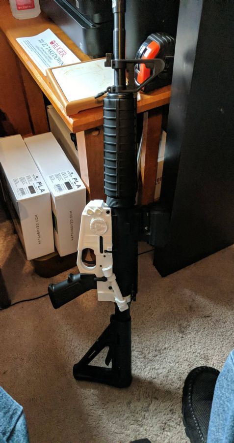
|
|
|
|
[#17]
Quoted: I got my lower build kit, and got this thing assembled today, and I'm happy enough with it as a proof of concept. Earlier in the discussion someone mentioned being able to remove the wording, and medallion holder from the STL file but I don't have the know how or computing power to do it. Would anyone be willing to share the STL minus the Second Amendment, and medallion holder? https://www.AR15.Com/media/mediaFiles/56812/Anderson_Hell_Fire-1768634.jpg @603Born Did you still want the raised box around the 2A? or all flat? |
|
|
|
[#18]
Quoted: @603Born Did you still want the raised box around the 2A? or all flat? @MNGearhead I'd like it all flat if possible. |
|
|
|
[#19]
Quoted: @MNGearhead I'd like it all flat if possible. PM me your email |
|
|
|
[#20]
Has anyone had issues with the trigger and hammer pins being slightly larger than they should be? I feel that i have my machine dialed in pretty decent and haven't seen this issues with other types of lowers that I have printed. Just wanted to see if others are having the same issue.
Thanks, Chris |
|
|
|
[#21]
Quoted: Has anyone had issues with the trigger and hammer pins being slightly larger than they should be? I feel that i have my machine dialed in pretty decent and haven't seen this issues with other types of lowers that I have printed. Just wanted to see if others are having the same issue. Thanks, Chris the holes are teardrop shaped in the hellfire STL. which might lead to some of the feeling of looseness. assumedly to ensure good overhangs. |
|
|
|
[#22]
Quoted: the holes are teardrop shaped in the hellfire STL. which might lead to some of the feeling of looseness. assumedly to ensure good overhangs. Quoted: Quoted: Has anyone had issues with the trigger and hammer pins being slightly larger than they should be? I feel that i have my machine dialed in pretty decent and haven't seen this issues with other types of lowers that I have printed. Just wanted to see if others are having the same issue. Thanks, Chris the holes are teardrop shaped in the hellfire STL. which might lead to some of the feeling of looseness. assumedly to ensure good overhangs. Yeah I think you would be better off with a drop in trigger group and anti rotation pins. Basically none of the FCG pivoting will happen in the receiver holes and the bars on the outside of the anti rotation pins will keep everything aligned and secure. |
|
|
|
[#23]
Does anyone else feel like the upper/lower fitment is slightly off? It seems like the upper receiver needs to be able to slide back about a 4 hundredths of an inch more to be able to get a proper fit. I can pin the front and them push the rear in but you can see obvious outward flex in the front take down supports. I tired it with different uppers and I have to same issues so it isn't an out of spec upper. I also built the firebolt and vanguard u-bolt lowers and have the same issue. I was able to solve the problem with the vanguard by shaving material from the back where the buffer tube is. Most of that interference was from the forward assist. I wonder if these two lowers (anderson and firebolt) pulled form the same model when designing their lower.
|
|
|
|
[#24]
Quoted: Does anyone else feel like the upper/lower fitment is slightly off? It seems like the upper receiver needs to be able to slide back about a 4 hundredths of an inch more to be able to get a proper fit. I can pin the front and them push the rear in but you can see obvious outward flex in the front take down supports. I tired it with different uppers and I have to same issues so it isn't an out of spec upper. I also built the firebolt and vanguard u-bolt lowers and have the same issue. I was able to solve the problem with the vanguard by shaving material from the back where the buffer tube is. Most of that interference was from the forward assist. I wonder if these two lowers (anderson and firebolt) pulled form the same model when designing their lower. You need to calibrate your printer. Print something of a known length in mm and measure it. The formula is (expected length/measured length) * current steps in mm = new steps in mm So you print something 100mm long. It measures 98 mm long. Your current setting in steps is 100mm. (100/98) * 100 = 102.04 So you change that axis steps to 102. Print and re-test. There can sometimes be some overcorrection and it might take more than one calculation to get the best accuracy. Also bear in mind that the longer the test print, the better resolution you will have. For example, printing something 10mm vs 100mm with give 10x less resolution. You'd be better off printing something that's almost the total extent of your measuring calipers. |
|
|
|
[#25]
Quoted: Does anyone else feel like the upper/lower fitment is slightly off? It seems like the upper receiver needs to be able to slide back about a 4 hundredths of an inch more to be able to get a proper fit. I can pin the front and them push the rear in but you can see obvious outward flex in the front take down supports. I tired it with different uppers and I have to same issues so it isn't an out of spec upper. I also built the firebolt and vanguard u-bolt lowers and have the same issue. I was able to solve the problem with the vanguard by shaving material from the back where the buffer tube is. Most of that interference was from the forward assist. I wonder if these two lowers (anderson and firebolt) pulled form the same model when designing their lower. somewhere back there I posted a lengthy review.. my results printing in the usual (upside down) orientation was that the 1st layer with the brim and detritus from the raft left it slightly too tall so when the front takedown pin was inserted the rear couldnt be inserted but likewise if the rear were inserted the front wouldnt go it. my solution was to sand down the top of the lower until it did. however on the same printer I printed the receiver right side up in order to have a perfect top layer and in that case the fitment was perfect right from the get go. so net net.. you may want to do a calibration as suggested, but you may also just need to shave down any bottom layer roughness. a micrometer should be able to tell the difference. I would not recommend printing right side up unless there isnt another option. |
|
|
|
[#26]
Quoted: You need to calibrate your printer. Print something of a known length in mm and measure it. The formula is (expected length/measured length) * current steps in mm = new steps in mm So you print something 100mm long. It measures 98 mm long. Your current setting in steps is 100mm. (100/98) * 100 = 102.04 So you change that axis steps to 102. Print and re-test. There can sometimes be some overcorrection and it might take more than one calculation to get the best accuracy. Also bear in mind that the longer the test print, the better resolution you will have. For example, printing something 10mm vs 100mm with give 10x less resolution. You'd be better off printing something that's almost the total extent of your measuring calipers. I will take a look at my esteps using a longer print. They were calibrated with a 20mm cube. I did notice that part of my problem was from over tightening of the left / longer tension bolt. Fixing that helped the problem and some sanding on the buffer side put it where it should be. |
|
|
|
[#27]
What I did is set my e-steps without running the filament through the nozzle, just measured as it exited the extruder, and I haven't touched that setting since. Same for my z-offset(BLtouch ABL). I adjust my flow rate up or down depending on how the first layer looks. That method has worked pretty well for me so far.
If you calibrate your e-steps by feeding filament through the nozzle then you'll have to do this every time you swap in a different spool of filament, though you probably won't have to adjust flow rate much if at all. Personally I'd rather adjust flow rate, it's easily done on the fly from the printer's menu. |
|
|
|
[#28]
Anyone know if the bolt threads for the hellfire are a standard size? I've broken 2 so far in testing and I think actual bolts would be better in the rear. They're breaking right at the bottom of the socket for the allen key.
|
|
|
|
[#29]
Quoted: Anyone know if the bolt threads for the hellfire are a standard size? I've broken 2 so far in testing and I think actual bolts would be better in the rear. They're breaking right at the bottom of the socket for the allen key. Are you using 100% infill? Are they breaking during installation or during use? |
|
|
|
[#30]
100% infill, the heads popped off. One was during installation and the 2nd was when the rifle was leaned up against the safe and tipped over. I may try salt annealing the bolts and see if that helps. Bolts were printed horizontal with 100% infill and @ 225* esun pla+
|
|
|
|
[#31]
Forgive a newbie, but is that hideous bolt thing just to stiffen the lower?
|
|
|
|
[#32]
Quoted: Forgive a newbie, but is that hideous bolt thing just to stiffen the lower? That long one that runs at an angle? I would guess that's to stiffen the top of the receiver where the receiver extension threads in. |
|
|
|
[#33]
Quoted: 100% infill, the heads popped off. One was during installation and the 2nd was when the rifle was leaned up against the safe and tipped over. I may try salt annealing the bolts and see if that helps. Bolts were printed horizontal with 100% infill and @ 225* esun pla+ I printed horz. esun pla+, 212 deg 100% infil - i dont think I am having the same experience.. the bolts seem very secure and even the crappy looking first batch at .2mm didnt break at all. the .12 batch look and operate perfect. is it possible you are over tightening them? |
|
|
|
[#34]
whats the difference between the hellfire and wildfire?
|
|
|
|
[#35]
Quoted: whats the difference between the hellfire and wildfire? i dont think the wildfire has the diagonal supports for the buffer tube support. |
|
|
|
[#36]
Quoted: i dont think the wildfire has the diagonal supports for the buffer tube support. Quoted: Quoted: whats the difference between the hellfire and wildfire? i dont think the wildfire has the diagonal supports for the buffer tube support. Yeah I looked and found the differences.... I am going to try one soon... |
|
|
|
[#37]
Quoted: I printed horz. esun pla+, 212 deg 100% infil - i dont think I am having the same experience.. the bolts seem very secure and even the crappy looking first batch at .2mm didnt break at all. the .12 batch look and operate perfect. is it possible you are over tightening them? Yeah I could have over tightened them, I printed another set and I will put it through some tests. The printed bolt heads seem like the weakest point so if I have to I'll figure out a way to use a metal bolt. |
|
|
|
[#38]
Quoted: I printed horz. esun pla+, 212 deg 100% infil - i dont think I am having the same experience.. the bolts seem very secure and even the crappy looking first batch at .2mm didnt break at all. the .12 batch look and operate perfect. is it possible you are over tightening them? Quoted: Quoted: 100% infill, the heads popped off. One was during installation and the 2nd was when the rifle was leaned up against the safe and tipped over. I may try salt annealing the bolts and see if that helps. Bolts were printed horizontal with 100% infill and @ 225* esun pla+ I printed horz. esun pla+, 212 deg 100% infil - i dont think I am having the same experience.. the bolts seem very secure and even the crappy looking first batch at .2mm didnt break at all. the .12 batch look and operate perfect. is it possible you are over tightening them? I bet the printing orientation has something to do with it. Edit... Nope, he printed horizontal too. Might just be a bad spool of filament. |
|
|
|
[#39]
I have a certain color I am using for a lower build for a .22 conversion rifle.
Are there any buffer tubes and stocks that work together well? I have printed a bunch and either the buffer tube is huge/small or never prints correctly. I found a mini stock that is pretty sweet that was supposed to be press fit. The buffer I printed with it was waaay to big and it just falls right off a milspec buffer. |
|
|
|
[#40]
Quoted: I bet the printing orientation has something to do with it. Edit... Nope, he printed horizontal too. Might just be a bad spool of filament. I used Fusion Filaments HTPLA+ for mine. Bolts are a little tricky. .12 print @ no more than 40 speed. No supports or brim. Clean threads with a toothbrush then use a bic lighter to heat and smooth. Same with the nut sections. Then before assembling anything, run the bolts into the holes a bunch of times with a dap of grease. You should be able to hand screw them in. Make sure the shanks can go through the holes. I always needed to sand a little on the non-threaded section of the bolts. Then grease and hand fit. I had trouble with the pivot pin bolts stripping out. There are very few threads engaging. So I redid the pivot block by removing the tool holder and increasing the thickness of the main body (not the pivot pin hole part) 50%. Then stretch the bolts 50% in Cura and cut to fit. Much more secure. TYCOM |
|
|
|
[#41]
Quoted: 100% infill, the heads popped off. One was during installation and the 2nd was when the rifle was leaned up against the safe and tipped over. I may try salt annealing the bolts and see if that helps. Bolts were printed horizontal with 100% infill and @ 225* esun pla+ RANGE REPORT : took the hellfire, printed 30rd mag and printed 10/22 to the range. Hellfire : 1 round in mag, loaded and fired as expected, however on recoil the BOLT HEAD of the big long bolt for the buffer tube snapped off and hit me in the face. no damage to me, but the buffer felt too flexy at that point to fire any further rounds in that condition. Budlight, I think I am now agreeing with you, that a metal bolt may be better, or even redesign the file to take a more standard bolt and washer arrangement over the ridiculous 7mm bolt setup. slightly off topic but the printed 30 rd mag looks great and snaps into the lower nicely, but the clearances arent right for the upper, so something is slightly off there. will diagnose that separately. warfairy 10/22 receiver after all the minor fit and finish work necessary to build it ran perfectly for 25 rounds mag fed, and seems to have the stamina to be a reliable gun. eta. on closer inspection after stripping it, the 10/22 has developed a crack along the side of the right barrel attachment bolt line. the receiver is still whole and probably could continue to fire in that configuration for quite a while given that the stress line goes from the bolt hole to the side and the receiver is holding together, but for safety I am going to reprint it. i believe this was from some assembly issues however and not from firing. |
|
|
|
[#42]
I think the bolts themselves are plenty strong but the head is pretty thin between the allen socket and the edge of the bolt. I drilled and tapped a plastic bolt for 1/4-20 threads, the metal bolt mainly just holds the head on. I'll do some testing with it and see if it holds up better. A #7 drill bit and the tap fits perfectly inside the 7mm hex.
|
|
|
|
[#43]
on review of the damage, there is a real problem with the bolt design. the 7mm socket goes deep into the bolt, deeper than the head, so that where the shaft meets the head and the socket pocket extends there is only a thin wall diameter of about 2mm to hold the bolt together. the whole 11mm solid chunk of PLA+ and nothing but 2mm in a rough circle to actually hold the load.
also.. on review of the internet, this is such a weird size the whole receiver would need to be refactored to find a bolt that will actually fit it. so.. my idea.. remix the bolt itself. there is nothing behind the bolt to impinge on it, so make the bolt head taller (e.g. more head) - like 2x taller. then take the allen pocket out of the shaft and allow it only in the head and only after a nice 5-6mm buffer zone to allow the force to tranfer to the large head. |
|
|
|
[#44]
Quoted: on review of the damage, there is a real problem with the bolt design. the 7mm socket goes deep into the bolt, deeper than the head, so that where the shaft meets the head and the socket pocket extends there is only a thin wall diameter of about 2mm to hold the bolt together. the whole 11mm solid chunk of PLA+ and nothing but 2mm in a rough circle to actually hold the load. also.. on review of the internet, this is such a weird size the whole receiver would need to be refactored to find a bolt that will actually fit it. so.. my idea.. remix the bolt itself. there is nothing behind the bolt to impinge on it, so make the bolt head taller (e.g. more head) - like 2x taller. then take the allen pocket out of the shaft and allow it only in the head and only after a nice 5-6mm buffer zone to allow the force to tranfer to the large head. Let me know if you remix the bolt, what I did will probably work but I'd be interested in testing both. Mainly the main strut bolt since drilling and tapping it would just move the weak point further down the shaft. @bionicmonkey |
|
|
|
[#45]
Quoted: Let me know if you remix the bolt, what I did will probably work but I'd be interested in testing both. Mainly the main strut bolt since drilling and tapping it would just move the weak point further down the shaft. @bionicmonkey yeah, I think we're on the same wavelength here regarding the issue.. I like your fix, but long term I dont know if you can keep doing that without wear issues. I just remixed the bolts... printer is busy presently (lol, always a problem).. but next up I am going to print a new set of bolts. 3 main bolts and 1 strut bolt. by my math the bolt under the buffer has clearance issues and cant be fixed the same way. the right side main bolt for the buffer can be longer, as can the front bolts.. so i am starting there. if that works, I'll do a remix for the under the buffer bolt that simply has less engagement depth for the allen wrench. send me a a pm with your email addr and I will send u the files if u want. left is the remixed bolt, right is anderson hellfire original  |
|
|
|
[#46]
its called "2 bolts and a nut". https://www.thingiverse.com/thing:4728263/files
|
|
|
|
[#47]
Quoted: its called "2 bolts and a nut". https://www.thingiverse.com/thing:4728263/files Your link 404s. |
|
|
|
[#48]
Quoted: Your link 404s. ack.. sorry, i got a message saying I cant publish anything for 24hrs from account creation. so .. that will be the link, but It looks like it wont work until tomorrow. |
|
|
|
[#49]
I was looking into replacing the PLA bolts with metal.
It should be fairly simple. TinkerCad to plug the current bolt holes on the lower and buffer part (cylinder with a 5mm hole.) Long bolt would be 85 to 90mm, side bolt 40-45mm. Do the same with the front pivot pin part (remove the tool holder, plug holes, 5mm holes in plugs.) Round head allen bolts would be perfect with nyloc nuts. Washers too of course. On the bottom buffer bolt, fill in with plug and 4mm hole in lower so a 5mm bolt can thread itself in. Definitely round head bolt on this because of clearance issue. In the meantime I did reprint the bolts with the modified heads. If you reduce the depth of the allen receptacle, make a slot on the front of the bolt to help screwing it in/out. TYCOM |
|
|
|
[#50]

|
|
|
 Win a FREE Membership!
Sign up for the ARFCOM weekly newsletter and be entered to win a free ARFCOM membership. One new winner* is announced every week!
You will receive an email every Friday morning featuring the latest chatter from the hottest topics, breaking news surrounding legislation, as well as exclusive deals only available to ARFCOM email subscribers.

AR15.COM is the world's largest firearm community and is a gathering place for firearm enthusiasts of all types.
From hunters and military members, to competition shooters and general firearm enthusiasts, we welcome anyone who values and respects the way of the firearm.

Subscribe to our monthly Newsletter to receive firearm news, product discounts from your favorite Industry Partners, and more.
Copyright © 1996-2024 AR15.COM LLC. All Rights Reserved.
Any use of this content without express written consent is prohibited.
AR15.Com reserves the right to overwrite or replace any affiliate, commercial, or monetizable links, posted by users, with our own.