|
[#1]
They're CNC TIG or laser welded
You can do it if you have a lathe and a decent TIG. It's how all of my rifle can cores are put together, and a couple I have that are tubeless designs 
|
|
|
|
[#2]
Quoted:
They're CNC TIG or laser welded You can do it if you have a lathe and a decent TIG. It's how all of my rifle can cores are put together, and a couple I have that are tubeless designs https://i.imgur.com/S17MHK5.jpg |
|
|
|
[#3]
Quoted:
They're CNC TIG or laser welded You can do it if you have a lathe and a decent TIG. It's how all of my rifle can cores are put together, and a couple I have that are tubeless designs https://i.imgur.com/S17MHK5.jpg I saw on a SIG video where they show a snippet of a suppressor being built. Appears like they stack the baffles and caps together, drop it in a press to squeeze them together, then it goes to get welded. I saw Q had a welding set up that appeared to be very small able to be placed on top a desk. Any idea if this is a commercial off the shelf item or a custom built rig? |
|
|
|
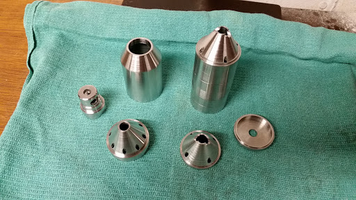
[#4]
Quoted: Wow, awesome! Do you have more pics of your work? Quoted: Wow, awesome! Do you have more pics of your work? The one above was a stubby .30 cal F1 can I recored for a local deputy. Only 7 baffles, but it worked out pretty well for the length. Before welding: 
Quoted:
I saw on a SIG video where they show a snippet of a suppressor being built. Appears like they stack the baffles and caps together, drop it in a press to squeeze them together, then it goes to get welded. I saw Q had a welding set up that appeared to be very small able to be placed on top a desk. Any idea if this is a commercial off the shelf item or a custom built rig? 
Each baffle has a stepped shoulder which fits snugly into the baffle behind it. Basically self-aligning as long as they're under tension, but still have to watch for distortion when welding. I tack each baffle every 90°, then do the circumferential welds, letting it cool and re-tightening the nut on the rod before each weld. The front cap is last, and the stack comes off the fixture and goes back in the lathe to make sure the face is true before welding the cap on. Most of the time I cut the threads on the front cap after welding. 
|
|
|
|
[#5]
Amazing. Thanks for the detailed response!
|
|
|
|
[#6]
Quoted:
They're CNC TIG or laser welded You can do it if you have a lathe and a decent TIG. It's how all of my rifle can cores are put together, and a couple I have that are tubeless designs https://i.imgur.com/S17MHK5.jpg |
|
|
|
[#7]
Quoted: Of course! Lol. Unfortunately, a lot of them were on my last phone, which died beyond recovery of anything in it. The one above was a stubby .30 cal F1 can I recored for a local deputy. Only 7 baffles, but it worked out pretty well for the length. Before welding: https://i.imgur.com/SxoSnbr.jpg There's more than one way to skin a cat. I'm planning to build a variable speed power unit to rotate the baffle assembly, but at this time still do it manually. I use a rotary indexer to hold a rod which aligns the baffles https://i.imgur.com/N4aS9hs.jpg Each baffle has a stepped shoulder which fits snugly into the baffle behind it. Basically self-aligning as long as they're under tension, but still have to watch for distortion when welding. I tack each baffle every 90°, then do the circumferential welds, letting it cool and re-tightening the nut on the rod before each weld. The front cap is last, and the stack comes off the fixture and goes back in the lathe to make sure the face is true before welding the cap on. Most of the time I cut the threads on the front cap after welding. https://i.imgur.com/9ICajlQ.jpg |
|
|
|
[#8]
Interesting, taggy.
|
|
|
|
[#9]
|
|
|
|
[#10]
Quoted:
Here's one I did https://lh3.googleusercontent.com/GRQ4It0vAf49jbcoJPldVj3w2rTil_x_OdPdRycxDNbj6wSaWYT9hIwcuuu7LPsV4j-GPa2pbbI1H8_uthdU6cYGFU3Lnx1EDT-pMAVcpJM4nPaxFc3-zsWderXxPUwQ1dJPjbLJ8A https://lh3.googleusercontent.com/6Hu-sSCL0qQ57iDDj5oD-ARPodcf4fmnCHfwe_MMl954aaluVQ52uJsZPdYoA-HofNPFw0nmd76fikgV_EO2nGZwQVPuRYTFRY7vNMO4hPM7U3knduzZIWwXVK-kKnHW-TmrylL40A https://lh3.googleusercontent.com/ls7DjSYNwf6GxvN4sRTZAdgGhSzUWpDrsOnRPCG6lBzhCulTOOjQ4jWpcWxK37W-G_2WareEvFIObqzjCQJkbBm9ZHzmkjDywfYkbV_1tJtKqISesawtXGAMrzLFwuNVf28ny8EZwA Here's a vid of the welding and rig I made. Mind if I ask what thickness you went with? Any would there be any technical reason that a tubeless welded stack couldn’t have removable ends? |
|
|
|
[#11]
Quoted:
Here's one I did https://lh3.googleusercontent.com/GRQ4It0vAf49jbcoJPldVj3w2rTil_x_OdPdRycxDNbj6wSaWYT9hIwcuuu7LPsV4j-GPa2pbbI1H8_uthdU6cYGFU3Lnx1EDT-pMAVcpJM4nPaxFc3-zsWderXxPUwQ1dJPjbLJ8A https://lh3.googleusercontent.com/6Hu-sSCL0qQ57iDDj5oD-ARPodcf4fmnCHfwe_MMl954aaluVQ52uJsZPdYoA-HofNPFw0nmd76fikgV_EO2nGZwQVPuRYTFRY7vNMO4hPM7U3knduzZIWwXVK-kKnHW-TmrylL40A https://lh3.googleusercontent.com/ls7DjSYNwf6GxvN4sRTZAdgGhSzUWpDrsOnRPCG6lBzhCulTOOjQ4jWpcWxK37W-G_2WareEvFIObqzjCQJkbBm9ZHzmkjDywfYkbV_1tJtKqISesawtXGAMrzLFwuNVf28ny8EZwA Here's a vid of the welding and rig I made. |
|
|
|
[#12]
Quoted:
Do you make the cones any thicker when you build one that way? Mind if I ask what thickness you went with? Any would there be any technical reason that a tubeless welded stack couldn’t have removable ends? Quoted:
Do you make the cones any thicker when you build one that way? Mind if I ask what thickness you went with? Any would there be any technical reason that a tubeless welded stack couldn’t have removable ends? A centerfire can doesn't need to be serviced. Other than trying it out on my 22lr, bolt rifle, a couple of times, it lives on my 10.3" carbine. Quoted:This is awesome. What are the baffles made of? |
|
|
|
[#13]
Quoted:
This is basically what I went from. I revised a tad, but not too much. A centerfire can doesn't need to be serviced. Other than trying it out on my 22lr, bolt rifle, a couple of times, it lives on my 10.3" carbine. Thanks for the PDF. What length/weight did you end up with? I think I see 6.5” on the F1? |
|
|
|
[#14]
Quoted:I wasn’t concerned about it being serviceable. Quoted:I wasn’t concerned about it being serviceable. I could see another option, whereby you make a welded stack that slides into one of the modular tubes you already own. Your mount and end cap options would already be available. Obviously, this wouldn't have the same weight saving benefit, but I was just throwing examples around. Quoted:Thanks for the PDF. What length/weight did you end up with? I think I see 6.5” on the F1? |
|
|
|
[#15]
Quoted: Strongly consider a pedal type switch on the rotary welding chuck along with a potentiometer to control speed. It makes a huge difference, I've found. |
|
|
|
[#16]
Quoted:Strongly consider a pedal type switch Quoted:Strongly consider a pedal type switch Quoted:Hand held speed control is the plan. I made a fixture to hold the torch using a magnetic indicator base. I align the torch, turn it on, flip the motor switch. A 4" piece of welding glass is fixed above so the weld can be observed. The welding rig's base is a piece of SS, deep strut channel. I keep the mag base touching it and the electrode square to the work. Once the tip distance is set, I can just slide the mag base down to the next weld and be ready to go. If I were to do this for production, I'd probably get a cheap and/or used lathe. Nothing special. Just a live center in the tailstock and the torch attached to the carriage. |
|
|
|
[#17]
Quoted: Hand held speed control is the plan. Trying to run two potentiometer pedals at once is a good way to change the thing you didn't intend to! |
|
|
 Win a FREE Membership!
Sign up for the ARFCOM weekly newsletter and be entered to win a free ARFCOM membership. One new winner* is announced every week!
You will receive an email every Friday morning featuring the latest chatter from the hottest topics, breaking news surrounding legislation, as well as exclusive deals only available to ARFCOM email subscribers.

AR15.COM is the world's largest firearm community and is a gathering place for firearm enthusiasts of all types.
From hunters and military members, to competition shooters and general firearm enthusiasts, we welcome anyone who values and respects the way of the firearm.

Subscribe to our monthly Newsletter to receive firearm news, product discounts from your favorite Industry Partners, and more.
Copyright © 1996-2024 AR15.COM LLC. All Rights Reserved.
Any use of this content without express written consent is prohibited.
AR15.Com reserves the right to overwrite or replace any affiliate, commercial, or monetizable links, posted by users, with our own.