


Armory Sponsor

DIY Annealing Machine (Page 11 of 17)

|
Originally Posted By RLR350:
Drfroglegs, Sounds like you have it hooked up right. I don't remember why I split/cut the wire. I think it was just easier to make the connection at that point rather then trying to get up to the controller. Your way is probably better and does the same thing. As far as I know hooking the negative of the sensor to a negative post on the power supply does the same thing as hooking it to the negative side of the motor. Good luck. Hopefully it's just a faulty sensor. On a side note I just put about a hundred 308 cases through mine yesterday and it worked without a flaw. The sensor is a great addition-no playing with the speed control anymore. Ok. I think I know the problem now. I believe you have a PNP sensor while I have an NPN sensor? I just hooked mine up to a power supply with a voltmeter to make sure the sensor works. For MINE, I have to hook it up the following way: Part Number: LJ12A3-4-Z/AX NPN NC Blue wire from sensor goes to -Motor on controller Black wire from sensor goes to one motor wire Brown wire from sensor goes to the other motor wire AND +motor on controller (shouldn't matter if you twist them together and screw to controller +motor connector or if you have a wire coming from motor and controller and twist all three wires together). I'll hook it up when i get home to double check, but the sensor works great with the power supply and volt meter hooked up this way. Thanks for your help! |
NRA Life Member
Second Amendment Foundation Member
FBHO Member
Second Amendment Foundation Member
FBHO Member


|
Originally Posted By Flashbang1:
The NPN switch breaks the ground- to the motor. The PNP switch breaks the feed+ to the motor. Simple diagram below should clear up any wiring issues. https://lh3.googleusercontent.com/-A8rOpKUa7Z0/VucohLe8jPI/AAAAAAAAJCE/Bulr4DLY9A88g8aVg8Xk1MlkNWh9yH01w/s1280/upload_-1 Well I just got home and hooked everything up and that was definitely the problem (followed the PNP diagram instead of the NPN). Those of you who are looking at the proximity sensor check out flashbangs post above for the correct way to wire in. My description works great for the NPN the NPN type but the wiring is different for the PNP. Thanks guys, on with the build. Now if I can just get my feed ramp angle correct... |
NRA Life Member
Second Amendment Foundation Member
FBHO Member
Second Amendment Foundation Member
FBHO Member

|
Ok. I've been working on this for a couple weekends and I have my DIY annealer working. Photos and video below.
I believe that I have slightly "over-engineered" this project. By that I mean I used some add-on bearings for the motor shafts, made adjustable motor mounts, used couplings and longer motor shafts, used my tap and die set more than ever, etc... Still, it was fun. However, after a couple of weekends into it my wife was getting pretty tired of me working in the garage and neglecting the family. Now, I have no special skills or privileges here (no machine shop or source of materials). I purchased the usual items like everyone else. I work for an electrical utility so I liberated an old electrical panel and an aluminum plate. My education is electronics and automation... and I save scrap/parts so most of this I had on hand. However, all the work is done with simple tools (jig saw, cheap drill press, vise, files, drills and drill motor, Dremil tool, etc). So, here it is, my version of the automated cartridge annealer. The case feeder is too large.... that will be cut down to be flush with the top of my electrical box. Ideally it works best with 20 to 30 cases and I monitor the process constantly because every now and then a cartridge will bounce and not land correctly. Still, most of the time I just keep loading in cartridges and it keeps doing it's thing. I followed most of the advice here, and with the proximity switch I went one step further and added an enable/disable switch to it and it also drives an auxiliary relay because these cheap prox switches really don't handle much current. My prox is the NC type with 4mm sensing distance. The first one I had would "chatter" when I turned it off because I was switching the (+) DC to it. I've changed my design to switch the (-) DC and that works perfectly. I also had to add a guide on my feed ramp to keep the cartridges close enough to the prox switch for proper function. Here's a slideshow of the pics I have.... Click Here So, here's my version.... 
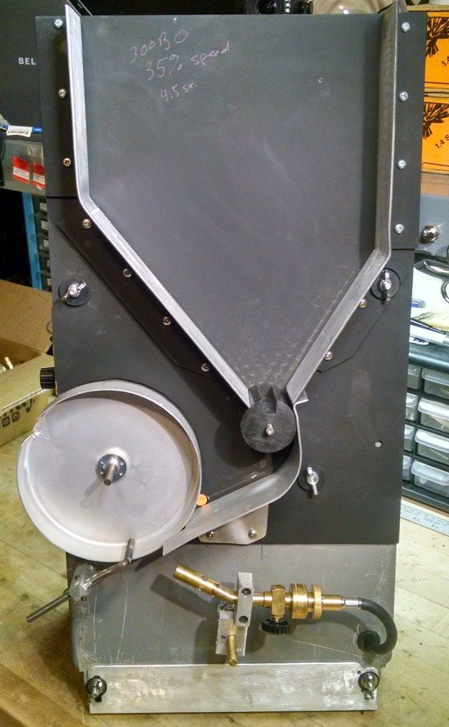


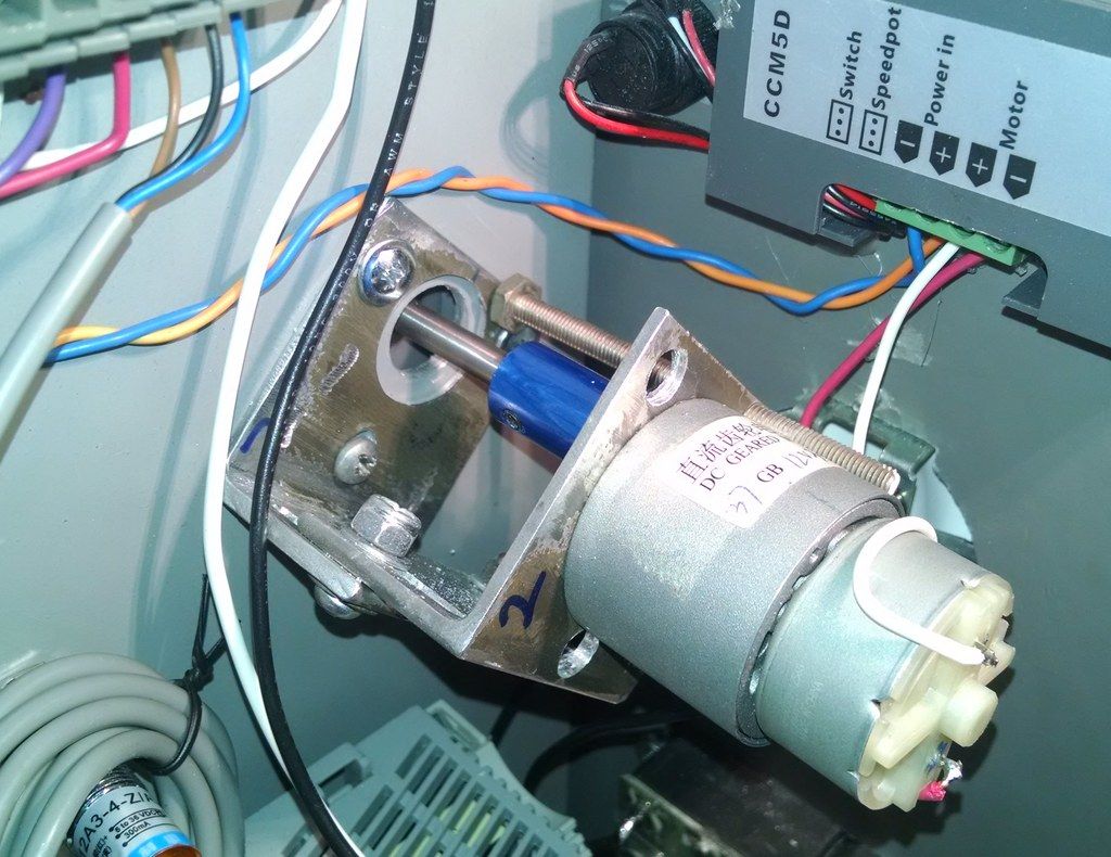
|
To really live, you must nearly die.
|
Originally Posted By SubgunFun:
......... snip..............and I monitor the process constantly because every now and then a cartridge will bounce and not land correctly. ........ snip............. I have a suggestion to help reduce case bounce. Your pan slot looks a little rough. Be sure nothing is catching on your cases as they enter the pan. Cases go into the pan best if they are held in the waiting position just a little bit toward the front face of the annealer. That would be away from what would be the bottom of the cake pan, if you were baking a cake. The cartridge cases drop in best if they start with the heavier base of the case going in first. That can be accomplished by angling the leading edge of the slot. Put your thinking cap on to be sure you angle it the correct way. In other words, as the slot rotates to the point where the case is ready to drop into the annealing pan, you want the leading edge to be angled just a tiny bit so that the case base is released first. That will help stabilize the case as it falls toward the case stop rod. Finally, you might experiment with moving the stop rod so that the case is held closer to the feed ramp; i.e. it will have a shorter distance to fall. You'll have to re-aim your torch of course. Congratulations on another "Skip" build and good luck. |
|
SubgunFun,
Nice work! Some helpful tips to get rid of your gremlins. Your feedback ramp is too long and too steep. Move your pan up and to the right closer to the feeder drum. Also reverse your feeder motor rotation to spin counterclockwise and place your ramp directly under the drum. Case stop rod should be as high as it can be off the pan without allowing a case to roll under it. This should end all issues. |
|
I did build in an adjustable lean using angle on the bottom front. I fiddled with leaning it back more but reliability wasn't increased that much. I'll end up modifying the design a tad on the feed ramp guide and also tweek the opening in the drumb so the base starts to fall in place first.
Yes, my feeder is too high. Unfortunately, with my bearings mounted in the panel, it is a bit of work to lower it. Hence the clockwise rotation and extended drop of the feed chute. I was thinking the case stop rod should be low, but it does make sense now to mount it higher. The nice thing is most everything is modular and really easy to change or modify (except for my motor/bearing placements). Thanks for the input! -SubgunFun , |
To really live, you must nearly die.
| Im gathering parts and have some ideas to share. If your looking for the 12v power source. a good place to look is your local Good Will. they have a lot of junk electronics and even a section of just power sources. I picked one up for .99 So that's pretty cheap and no waiting on shipping. |
|
OK I have a question, I have pretty much all the parts and started building. Im having an issue with the main pan. I know its important to get that running really smooth but My motor has some play in the shaft which translates to wobbling. Are you guys running the pan seated against the back board for stability? I saw one picture way back where someone used lexan and had the pan coupler running against that. My coupler is real solid and has no play its internal to the motor. ideas?
|
|
Originally Posted By rotortuner:
OK I have a question, I have pretty much all the parts and started building. Im having an issue with the main pan. I know its important to get that running really smooth but My motor has some play in the shaft which translates to wobbling. Are you guys running the pan seated against the back board for stability? I saw one picture way back where someone used lexan and had the pan coupler running against that. My coupler is real solid and has no play its internal to the motor. ideas? Mine is attached to shaft on both drums with no other support. I noticed the same wobble, it isn't as much of an issue as you would think. Concentricity is more important. |
|
That might of been mine with the lexan. I drilled a hole the diameter of the coupler. It acts as a guide for the end of the coupler where it meets the pan. It took most of the wobble out that was occurring with the loose motor arbor.
The next part is to center the pan on the arbor. This is why I put the bend/down ramp on the piece of metal that the empty cases roll on while waiting to feed. I use the angled ramp as a means to adjust the pan center by using the gap as a measurement as the pan turns. When the gap is at the widest point I stop the pan and adjust it closer which evens it out. However, as long as the gap never becomes too big, preventing the case from entering right, the wobble/off center isn't a problem with function. It is annoying to watch an off center pan though. 
|
| OK thanks for the info. I got my main pan running pretty smooth. Your right the little wobble doesnt seem to affect anything. I think I cut my pan to short so Im going to have to pick up another and keep it out aroun 1.3" or so. Primarily doing 308. Im going with a wood feeder drum. Found a furniture leg at home depot for 6 bux, Will post some pics once i get a little further along. fun little project. Only downside is, parts add up, some stuff I have score real cheap but then like the pans Im in almost 17 bux.. Thanks for the info. |

|
Thanks to all who've contributed to this thread. My shameless copy is about ready for a real run.
My only original ideas here were using some random plumbing fittings I had to mock up the torch holder and shell support. A 1/2 x 1-1/2 brass nipple jammed into a ~5/8 hole at top left with a 1/2"FIP x 1/4 od compression fitting screwed to it to hold the 1/4" aluminum rod. Makes it a snap to adjust or remove. I went a little nuts with the length of the shell holder, but I wanted it to act like a heat sink and it seems to be working well. For the torch holder, I have a 3/8 floor plate attached to a split ring hanger made for 1/2" copper. It's way too loose so I sort of shimmed it up with some thin metal plumber's tape for now. Seems to work fine so it may stay this way. I hacked a u-bolt I had laying around to get me the 2" of threaded rod needed to connect the two pieces. Keeps tension while allowing for easy minor adjustments to the flame angle. 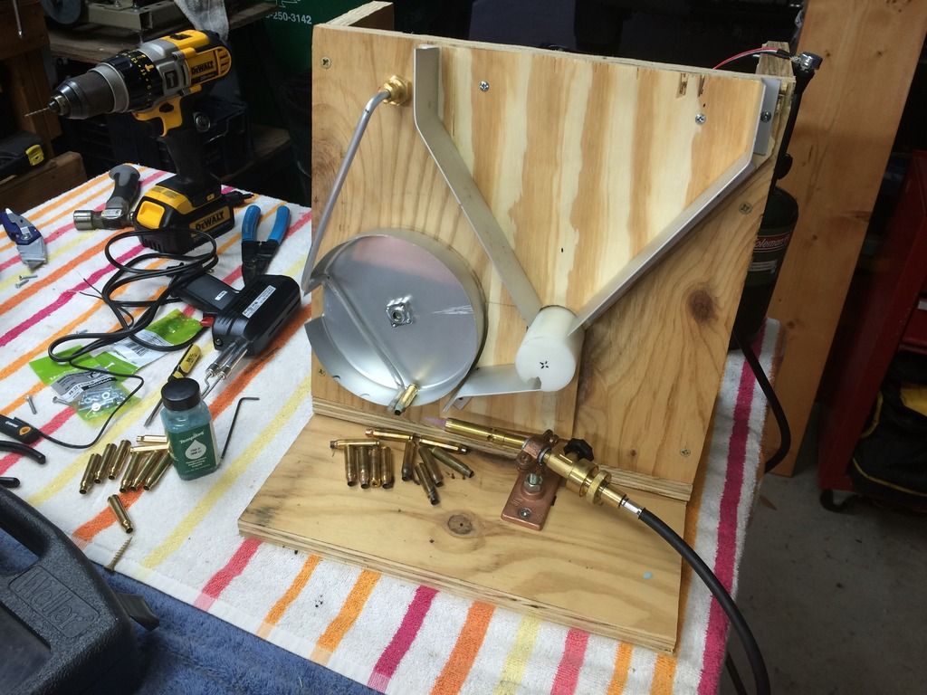
|
|
so I wanted to build an annealer. I found the J morris one and got a plate from him. I had it about done, and found one made by skip. I could see right away it was a better way to go. then I found a guy with a blue one, and it was even better!!! so off I went, and built one from skips plans, and measuring the computer screen on the blue nasty. THANKS to both you guys, and mr long range for the idea. then I got a email from u tube with another video posted for the annealer with the feed motor switch, so in hunting down a switch of course I got the wrong one. so when I was looking for another one to try, I found this thread. It would have been nice to have found it first, but that is how I roll, I throw out instructions! HA. so now I am waiting for the switch from china, got 2 in case I blow it up. here is a link to the one I built, thanks to all that helped make this machine. I do mostly 308, and it rocks! and when the switch arrives, the timing issue will be gone, and I can nap will it runs.!
ha! http://vid1084.photobucket.com/albums/j412/rlporter507/M4H01506.mp4 |

|
Originally Posted By rlporter:
so I wanted to build an annealer. I found the J morris one and got a plate from him. I had it about done, and found one made by skip. I could see right away it was a better way to go. then I found a guy with a blue one, and it was even better!!! so off I went, and built one from skips plans, and measuring the computer screen on the blue nasty. THANKS to both you guys, and mr long range for the idea. then I got a email from u tube with another video posted for the annealer with the feed motor switch, so in hunting down a switch of course I got the wrong one. so when I was looking for another one to try, I found this thread. It would have been nice to have found it first, but that is how I roll, I throw out instructions! HA. so now I am waiting for the switch from china, got 2 in case I blow it up. here is a link to the one I built, thanks to all that helped make this machine. I do mostly 308, and it rocks! and when the switch arrives, the timing issue will be gone, and I can nap will it runs.! ha! http://vid1084.photobucket.com/albums/j412/rlporter507/M4H01506.mp4 Here I made it hot for you Video, oh and good job I need to put mine together. I have purchased all the parts for the build and cut the wood out. However that is where it has set since before Christmas. |
|
Hey all, I've been following this thread for a while now and I'm finally getting around to my own. I'm having problems with the NPN sensor. No matter what I do I can't get it to work properly. I've tried both NPN and PNP configurations.
This is the sensor I have: http://www.ebay.com/itm/351041800052?_trksid=p2057872.m2749.l2649&ssPageName=STRK%3AMEBIDX%3AIT Here's a picture of how I have it wired. Nothing lights up on the sensor, whether there's something in the way or not. Motor doesn't get any power either. Am I doing this totally wrong or did I get a bad sensor? If I hook the brown to positive and black to negative power feeds I do get the light on the sensor lit up, but no matter where I put blue I can't get the motor to spin. 
|
|
Originally Posted By tzzler44:
Hey all, I've been following this thread for a while now and I'm finally getting around to my own. I'm having problems with the NPN sensor. No matter what I do I can't get it to work properly. I've tried both NPN and PNP configurations. This is the sensor I have: http://www.ebay.com/itm/351041800052?_trksid=p2057872.m2749.l2649&ssPageName=STRK%3AMEBIDX%3AIT Here's a picture of how I have it wired. Nothing lights up on the sensor, whether there's something in the way or not. Motor doesn't get any power either. Am I doing this totally wrong or did I get a bad sensor? If I hook the brown to positive and black to negative power feeds I do get the light on the sensor lit up, but no matter where I put blue I can't get the motor to spin. http://i212.photobucket.com/albums/cc87/tzzler44/20160403_221239_zps1uc10wtr.jpg This is how I have mine hooked up assuming your brown and red cables go to the - Motor and +motor output from your controller or a power supply. You can hook up the switch directly to the power supply and replace the motor with an ohm meter to see if it is working properly. Also make sure you have the controller knob turned up (if you have a controller on the motor). Tell us what your entire setup is. Controller? What is your power supply? Here is my setup with a motor controller and the eBay 12v 5a power supply. 
|
NRA Life Member
Second Amendment Foundation Member
FBHO Member
Second Amendment Foundation Member
FBHO Member
|
Originally Posted By tzzler44:
Hey all, I've been following this thread for a while now and I'm finally getting around to my own. I'm having problems with the NPN sensor. No matter what I do I can't get it to work properly. I've tried both NPN and PNP configurations. This is the sensor I have: http://www.ebay.com/itm/351041800052?_trksid=p2057872.m2749.l2649&ssPageName=STRK%3AMEBIDX%3AIT Here's a picture of how I have it wired. Nothing lights up on the sensor, whether there's something in the way or not. Motor doesn't get any power either. Am I doing this totally wrong or did I get a bad sensor? If I hook the brown to positive and black to negative power feeds I do get the light on the sensor lit up, but no matter where I put blue I can't get the motor to spin. http://i212.photobucket.com/albums/cc87/tzzler44/20160403_221239_zps1uc10wtr.jpg For a three wire NPN switch your picture shows the correct wiring. Assuming the motor works with a direct feed without the switch from the power source your using, the switch is defective. I don't know what light your speaking of. I will say this, that eBay vendor is shifty as I ordered from him and had issues. Item listed was not what was sent to me. I was sent a NO PNP switch and looked used. Your eBay link list a two wire switch, yet you have a three wire switch. I'll bet the switch is defective. |
|
Thanks for the replies, guys.
Flash, not sure where the ebay link is taking you, but it takes me to a three wire sensor, NPN NC. Not a big deal though. The light I was talking about is one the very back of the sensor, supposed to light up when the gate is open I guess. I'll throw up a picture of the label on the switch. Thanks for the reassurance on the wiring! Skip, I hope you're right. I'm going to get another sensor from Amazon. Gonna go with this one. Hopefully it'll work I'm glad these things are super expensive. 
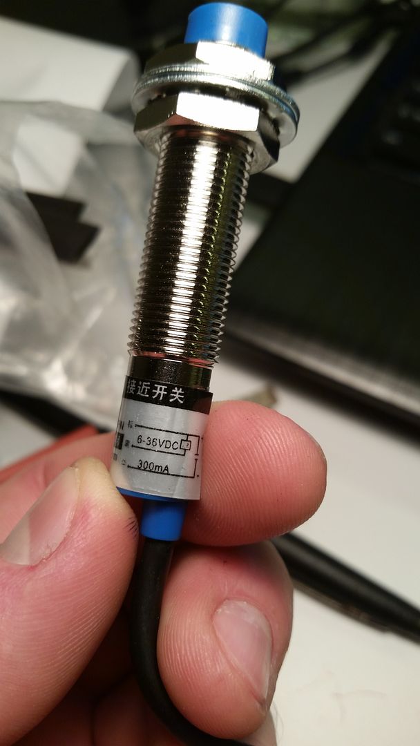
|
|
The 8mm sensor has a diameter of 15mm... bigger than the 4mm sensor you had but I don't think it would be unusable. I think I used this one and it came pretty quickly. Note the shipping times on some of these from Amazon can take a while.
As I mentioned earlier, I added a small switch series with the (-) feed DC to the prox switch. It's handy to shut off the feed system for testing/setup or if something goes awry. Originally Posted By tzzler44:
Thanks for the replies, guys. Flash, not sure where the ebay link is taking you, but it takes me to a three wire sensor, NPN NC. Not a big deal though. The light I was talking about is one the very back of the sensor, supposed to light up when the gate is open I guess. I'll throw up a picture of the label on the switch. Thanks for the reassurance on the wiring! Skip, I hope you're right. I'm going to get another sensor from Amazon. Gonna go with this one. Hopefully it'll work I'm glad these things are super expensive. |
To really live, you must nearly die.
| Subgun, yeah maybe keeping the diameter smaller is a good idea. I was thinking 8mm would be nice for the longer range but now that I think about it there's no point. If the brass is more than 4mm from the sensor I've done something wrong. Ordered the 4mm version. Should be here on wednesday. |

| The problem you're going to run into with the proximity sensor is that it isn't designed to switch a large load. It's says it's rated 6V-36V. If you try with a higher voltage than 12V, say 24V it will probably turn on the motor. Otherwise, you're going to have a bias the motor with a resistor. Here's a link to an instruction sheet, see page 9 regarding switching incandescent loads, same applies to the motor. You can approach the issue by either biasing the motor or using the sensor to switch a relay controlling the motor. |
"...in any society, Law is an illusory concept that works only when everyone voluntarily agrees to live by it." -Massad Ayoob
|
Originally Posted By CS223:
The problem you're going to run into with the proximity sensor is that it isn't designed to switch a large load. It's says it's rated 6V-36V. If you try with a higher voltage than 12V, say 24V it will probably turn on the motor. Otherwise, you're going to have a bias the motor with a resistor. Here's a link to an instruction sheet, see page 9 regarding switching incandescent loads, same applies to the motor. You can approach the issue by either biasing the motor or using the sensor to switch a relay controlling the motor. The running load on the motor is very small at .098Amps. The switch is rated for 300mA. I see no need to use a relay. |
|
Originally Posted By Flashbang1: The running load on the motor is very small at .098Amps. The switch is rated for 300mA. I see no need to use a relay. Originally Posted By Flashbang1: Originally Posted By CS223: The problem you're going to run into with the proximity sensor is that it isn't designed to switch a large load. It's says it's rated 6V-36V. If you try with a higher voltage than 12V, say 24V it will probably turn on the motor. Otherwise, you're going to have a bias the motor with a resistor. Here's a link to an instruction sheet, see page 9 regarding switching incandescent loads, same applies to the motor. You can approach the issue by either biasing the motor or using the sensor to switch a relay controlling the motor. The running load on the motor is very small at .098Amps. The switch is rated for 300mA. I see no need to use a relay. That's running load. The start current or locked rotor amps is going to be higher. I had to bias mine with a 1k resistor to get it to reliably work at a lower voltage. It did fine at 17V but 9-12V it would not switch. Thought the sensor was bad but it wasn't. |
"...in any society, Law is an illusory concept that works only when everyone voluntarily agrees to live by it." -Massad Ayoob
|
Im using this relay and it works good so far, the sensor clicks it no problem. its actualy two relays in one, so i have an additonal relay for something else that could use a sensor too.
http://www.ebay.com/itm/201488342161?_trksid=p2057872.m2749.l2649&ssPageName=STRK%3AMEBIDX%3AIT |
|
So either I have the worst luck with sensors or I'm doing something terribly wrong. I got thissensor in the mail today, hooked it up properly and plugged in the power supply, which my multimeter is telling me is putting out 12.1 volts. The motor turns on... and stays on no matter what I do with the sensor.
Apparently I can't embed youtube videos, so here's a link to the video of the problem: https://www.youtube.com/watch?v=GQvaIeOTKzo |
|
Originally Posted By tzzler44:
So either I have the worst luck with sensors or I'm doing something terribly wrong. I got thissensor in the mail today, hooked it up properly and plugged in the power supply, which my multimeter is telling me is putting out 12.1 volts. The motor turns on... and stays on no matter what I do with the sensor. Apparently I can't embed youtube videos, so here's a link to the video of the problem: https://www.youtube.com/watch?v=GQvaIeOTKzo I'll embed for you, I think you have to be a team member to embed youtube videos.
You have to put something metallic up against the sensor :) It is an inductive proximity sensor, your hand and the desk shouldn't work! It looks like it is working correctly, you just need to put a case within 4mm of the sensor to turn the motor off. |
NRA Life Member
Second Amendment Foundation Member
FBHO Member
Second Amendment Foundation Member
FBHO Member
|
Originally Posted By tzzler44:
DrFroglegs - you're my hero. All is well!  Haha. I did exactly the same thing when I had mine hooked up to a power supply and ohm meter.. I had the duh moment as well 
Glad it is working now! |
NRA Life Member
Second Amendment Foundation Member
FBHO Member
Second Amendment Foundation Member
FBHO Member
|
so I am waiting on my feeder switch, so I tore my annealer apart. Mainly cosmetic changes, shamelessly stolen from pictures of other annealer's on this form. thank you.
here is how I did the hub on the drum motor. A bolt, drilled for the motor shaft, with a threaded hole in a flat to hold it on. quick fix. got my cake pans from hobby lobby, 6 inch. I will post a new video when it's back together. 
|
|
switch came, "ITS ALIVE!!!!!" thanks to a dead computer, robbed the power cord and plug, and the fan. not really needed, but thought it looked neat. next trip to the hardware store, some hinges for a back door, and some rubber feet. I cut the pan using a dremal tool, clamped to the cross feed of the lathe, and turned the head stock by hand VERY SLOWLY! you should have see the first pan I tried to cut with it running with a bit! came out and wrapped around the tool post.
I have made spacers for the pan for different calibers, and another shallow pan to do 221 fire ball. it will do a 3006 case with the spacers out on the deep pan. the wing nut makes pan and spacer changes fast. I have the case feeder drum slot just deep enough so two 221 cases will not drop, and the 308 sticks up a bit but still stays in. so no need for 2 slots. the only problem I had was when the case feeder bin was full it was to much weight for the motor to turn at low voltage, but the switch cured that problem along with the timing issue. great idea, thanks to all who helped again! |

Global Warming Hoax Skeptic before it was cool
Joined:
Jun 2007
Posts:
40130
EE: 100% (1)
 WA, USA
|
Originally Posted By rlporter: switch came, "ITS ALIVE!!!!!" thanks to a dead computer, robbed the power cord and plug, and the fan. not really needed, but thought it looked neat. next trip to the hardware store, some hinges for a back door, and some rubber feet. I cut the pan using a dremal tool, clamped to the cross feed of the lathe, and turned the head stock by hand VERY SLOWLY! you should have see the first pan I tried to cut with it running with a bit! came out and wrapped around the tool post. I have made spacers for the pan for different calibers, and another shallow pan to do 221 fire ball. it will do a 3006 case with the spacers out on the deep pan. the wing nut makes pan and spacer changes fast. I have the case feeder drum slot just deep enough so two 221 cases will not drop, and the 308 sticks up a bit but still stays in. so no need for 2 slots. the only problem I had was when the case feeder bin was full it was to much weight for the motor to turn at low voltage, but the switch cured that problem along with the timing issue. http://vid1084.photobucket.com/albums/j412/rlporter507/M4H01509.mp4 great idea, thanks to all who helped again! Since I quoted your post, I see what's wrong. You have to be a Team Member to post videos. The hot link above does work. |
Selling agent for Algores carbon credit scam.
Shooting and Reloading, one hobby feeds the other.
Shooting and Reloading, one hobby feeds the other.
|
Originally Posted By rlporter:
switch came, "ITS ALIVE!!!!!" thanks to a dead computer, robbed the power cord and plug, and the fan. not really needed, but thought it looked neat. next trip to the hardware store, some hinges for a back door, and some rubber feet. I cut the pan using a dremal tool, clamped to the cross feed of the lathe, and turned the head stock by hand VERY SLOWLY! you should have see the first pan I tried to cut with it running with a bit! came out and wrapped around the tool post. I have made spacers for the pan for different calibers, and another shallow pan to do 221 fire ball. it will do a 3006 case with the spacers out on the deep pan. the wing nut makes pan and spacer changes fast. I have the case feeder drum slot just deep enough so two 221 cases will not drop, and the 308 sticks up a bit but still stays in. so no need for 2 slots. the only problem I had was when the case feeder bin was full it was to much weight for the motor to turn at low voltage, but the switch cured that problem along with the timing issue. http://vid1084.photobucket.com/albums/j412/rlporter507/M4H01509.mp4 great idea, thanks to all who helped again! Nice video... the setup looks great! |
To really live, you must nearly die.
|
OK here is my version. Heavy varnished model, to match my benches :) only hand tools used, no lathe and no mill.
From the top of my head: Cordless drill circle saw screw driver tape measure wood cutter fly bit tin snips soldering iron hole saw scroll saw hack saw paint brush electric grinder I used the motors and speed control from the original post. 6" pan from walmart. I used a $1 power converter I got from Good Will. 1/2" plywood for main box and front stand off. shimmed motors in rear with just 1/8" shim from hobby store. The key to not using a lathe or mill are these two parts: 1. Motor coupling from an RC airplane, its an electrifly GPMQ4945. With that coupler, you just put it on, tighten the set screw onto the motor shaft and drill a hole in the pan and add a couple of washers to take up the distance. I put a picture of the package below. I used two of these, one for the main drum and one for the feeder. they cust about 8 bux each 2. Feeder drum. I used a round furniture leg from home depot. Don't have the part number, but its in the wood area where they sell replacement mini legs. It already had a center hole located and I just cut it in half. it was kind of cone shaped which still works find. cut a slot in it by drlling successive holes and used a grinder to connect them into a notch. this doesn't have to be that precise. My notch feeds 223 to 30/06 no mods and I think If I use washer behine it will feed 300wm. Picture below shows the drum and the part I cut off. I also thought about buying a really cheap used wood baseball bat from Good will since its round, but it didn't have a centered hole already. I varnished it to make it slippery. 


Went with this cheapo, doesn't get warm or anything, shows how little the motors really draw. 
Used the RC quad copter power distribution board from ebay for 3 bux to split out power easily and get + - to where I need it. 
feeder drum from the cut down leg, I had to use the wood fly bit to bring the inside down to where I could get the nut on. 
shows the pan sitting directly on the hub. with 1/2" ply wood, I used two 1/8" shims in the rear. 
shows the feed drum with the piece I cut off with a hacksaw. 
shims I used. one under the feed drum motor, 2 under the main rotor motor. 
fender washer stack up on the main drum: I used 8mm SS 304 rod for the stop. you can hold a flame on it forever and the other end doesn't even get warm. they sell this on ebay and the 8mm linear track holder holds it. I used the sensor that was called out earlier and a switch to shut it off which is super handy. I picked up the propane tank holder but haven't mounted it yet and still have to mount the torch. Also picked up some nice feet from HD. I plan to use 3 feet so its always balanced. I also added the handle on top to pick it up. The auto switch is awesome. My contribution is the motor couplings and easy to make feeder drum. people were buying the expensive plastic, but this is way cheaper. The motor hubs also simplify greatly the couplings and motor mounting. I may also add another case sensor for above the feeder and have it sound an alarm, as a low case level alarm. but probably not needed as its fun to watch operate. My only challenge left is im having a little issue with cases nose diving a bit on 223 cases. I think its because at the rear where the case head sits against the rear, I need a gap between that and the drum. basically the case head is sitting square against the rear back there and when released the front moves first and it nose dives. any other symptoms of nose diving cases? https://m.youtube.com/watch?v=xncuUgItTeU https://m.youtube.com/watch?v=xEcQAZL49WM https://m.youtube.com/watch?v=buekCMXtrzc |

|
Originally Posted By Flashbang1:
rotortuner, We'll done. Link a video of you case nose dive issue so we can see a fix. OK I linked the Youtube vids in the original post at the bottom. Not sure which order they ended up in, but one of them shows 308 which runs pretty good, im happy with it, pretty consistant. the other shows 223 and you can see the inconsistency and the 3rd video shows close ups of the 223 falling in. open to suggestions. planning to cut anoth pan soon and make a little deeper but i think the issue is in the ramp, hoping i dont need an angle change because that would mess up the sensor placement, maybe a bent lip on the end of the ramp? I tried a piece of thin plastic over the sensor to make the back real smooth, made no difference. |
|
Few observations.
Your going too fast. The probable cause is your feed ramp is too long and more importantly too wide. What is occuring is that the "tail" you have going past the pan is holding the neck end of the case from rolling off while the trailing slot cut on the pan kicks the head end of the case up inducing nose dive. Get rid of that ramp tail. The angle looks fine. Make a new feed ramp to go straight into the pan, the give it a bend that's about 3/8" long. Set it so it's just not hitting the pan, about 1/8" away or so. The pan slot should be 1.25" wide or a little wider. Ramp should look like the one in the photo. 
Another thing to look into. The bottom of your pan slot should be very smooth and filed flush with the pan back side. Take a look at my pic 
The pan should be set back from the feed ramp riser board 1/8" or so. |
|
I purchase this 10 turn pot. http://www.ebay.com/itm/121005352097?_trksid=p2057872.m2749.l2649&ssPageName=STRK%3AMEBIDX%3AIT
I thought I had read in this thread about someone recommending it but I can't find the post now. being legally blind and not really understanding electricity, I don't know how to hook it up. I have the 2 wires from the power supply and this pot has 3 terminals. any help? Thanks roger |
Flashbang1 has some good advice. Here's a picture of my rig (posted earlier in this thread):
 _DSC3267 _DSC3267
It's hard to see but the pan is spaced back 4mm or so from the base of the case as the next case is in the resting position on the feed ramp. When the case enters the pan, it doesn't touch the back face of the pan. I have also put a slight angle on the leading edge of the pan opening so that the base of the case is released a fraction of a second early. That allows the case to fall into the pan base first. Put your thinking cap on when you slant the leading edge to be sure you angle it the correct way. This might be a good time to re post my caliber changing shim. It lets me switch from .223 to the much shorter 6mm BR case in about 10 seconds. It's much easier than shimming the entire back face of the pan. It's simply a piece of brass tubing and a bit of brass shim stock which slips over the case-stop-rod.  _DSC3380 _DSC3380
|

| I appreciate the help, Flash bang pretty much listed everything it could be causing my nose dive issue and I messed around with it a bunch more. My problem is that the pan was too flush with the stand off which is causing the case head to drag a little on the inside of the pan as it falls. I put a small spacer behind the case head to see if it would fall straight and it does with that extra clearance. I think my face plate is angled more than most I have seen on here so I think the case head may be a more succeptable to the drag as it falls. To remedy it, im going to add 3 washer under the motor mount to space the pan back a bit. I think that will make it run perfect. I also got my case stop rod adjusted back closer to the inside of the pan which helps too. Boy if I built another I could do it in a fraction of time with all the lessons learned etc. |
|
Originally Posted By corruptor:
Flashbang, are both of your cuts in the pan perpendicular to the bottom, or do you have the lead-in cut angled slightly to allow the base to drop in at the same time / slightly before the neck to avoid nose-dives? He said in his write up that he cut it slightly angled to avoid nose dive and you can see it in the picture that its angled a little compared to the trailing edge cut. |
DIY Annealing Machine (Page 11 of 17)
Armory Sponsor