Warning


Close

Confirm Action

Are you sure you wish to do this?

Confirm Cancel
BCM
User Panel

Page AR-15 » AR-15 / M-16 Retro Forum
AR Sponsor: bravocompany
Site Notices
Posted: 5/13/2021 12:14:47 AM EDT
Howdy!  In this article we're going to take a detailed look at an early production Robinson Armament M96 rifle in 5.56mm.  Designed as a modular firearm that could be reconfigured from a rifle with varying length barrels to a top feed automatic rifle with offset sights, to a promised but ultimately unrealized belt fed contraption, the M96 was built from 1999-2005.  Exact numbers produced are unknown but guesstimated to be around 3500.  

Although the basic design remained unchanged throughout production, various parts of the rifle were upgraded/redesigned over time.  Some early rifles ran perfectly and some had parts breakage and reliability problems.  The general consensus is that not all of the various bugs were ever truly worked out and you either got lucky with a good rifle or unlucky with a bad rifle.  Eventually, RA moved on to other designs and dropped the M96 from their catalog.  Unfortunately, and much to the chagrin of M96 owners, RA stopped selling spare parts and servicing the rifles almost immediately after stopping production and replacement parts are all but nonexistent now.  In early 2020, RA announced that they planned to do another small production run of the rifles using a mixture of NOS and new made parts but to date, this has been vaporware.  

As stated earlier, the example we are going to look at here is an early production base model rifle with a 20 inch, 1/9 twist, non-chrome lined barrel.  I am told it was originally purchased by HP White Laboratory in Street, Maryland where it sat either unfired or fired very little until March of 2020 when it was sold off.  It clearly shows evidence of being disassembled a number of times but I'd be surprised if it was fired other than initial testing.

The reason I am writing this is because there is only spotty information on the net about these early rifles.  Although there is a manual available for download, it is the 2002 version which covers none of the early features as found on this example.  SO.... what we are going to do here is to first take a fairly detailed and dedicated look at this particular rifle from stem to stern.  Then we will disassemble it piece by piece until it is fully field stripped and look closely at many of the parts.  At that point, I will go over how to properly disassemble it for both a general and thorough cleaning.  Finally, we will compare it to an earlier design that the M96 was loosely based on.  This is going to take a number of posts stretched over a number of days so what do you say we get started?  


First up are left and right side views of the M96:


Technically speaking, this is called the "M96 EXPEDITIONARY RIFLE" and all versions were marked the same regardless of how they left the factory.  There was a 16" carbine version available called the "RECON" and a 17.5" version with no particular name.  There were also 100 kits made that allowed you to temporarily convert your receiver to a top feed rifle with offset sights. Robinson said that a belt fed version was in the works but that never came to pass.  That's unfortunate too because I think it would have been neat.  


Here we see the M96 with an AR15 and AR-180 for size comparison:

At about 39.75" and approx. 8.4 lbs unloaded, the rifle compares favorably to the other two.  It's decently light if a little front end heavy and the controls are well placed.  The trigger pull is about the same as a standard AR15 and it uses the same magazines too.


Being manufactured during the 1994-2004 "Assault Rifle" ban, a flash hider was verboten!  Instead, we have an integral 6 holed muzzle brake:


Here's a closer look at the muzzle:

This mass of steel at the tip of the barrel is a large contributor to the slightly muzzle heavy feel.


Because the ban considered a threaded muzzle to be evil and profane, the muzzle brake is not removable and is machined as part of the barrel:


The only markings that I am aware of on the barrel are found on top between the front sight assembly and the muzzle brake:

"RA" obviously stands for Robinson Armament and I assume that they made the barrel inhouse.  It has a phosphate finish and is unlined.  I do not know if it is hammer forged or button rifled.


Left and right side views of the front sight assembly:


Notice that there is only a block of steel where a bayonet mounting point would be because the ban said such things were bad.
The fluted cylinder sticking out the front of the gas block is the gas adjustment valve.  We'll look at that a bit closer in a moment.
The white steel wire underneath the gas valve is a spring used to hold the valve at whatever setting you have selected.  
Note that the front sight base is adjustable for windage.  This is done using two hex head screws.

Here is a left side view of the front sight assembly showing the head of the left side adjustment screw and the tail of the right side adjustment screw:

Sorry it's a bit dark but it'll do.  To adjust windage to the right, you back off the left side screw and tighten the right side screw.  To adjust windage to the left, you back off the right side screw and tighten the left side screw.
BE CAREFUL with these screws and DO NOT go gorilla on them or they will strip.  Also, front sight windage is for gross adjustment only as the rear sight is windage adjustable too.  We'll look at that later.  
Last thing to point out in this picture is how much material there is on the barrel at this point and how much purchase the two gas block mounting pins have.  Nice.


The front sight post as seen from above:

It is a square post and adjustment should be obvious.  Please ignore the accumulated dust on the right sight ear.  It's been sitting a long time.


Front sight as seen from behind:

This has been a standard US arrangement for many generations now.


The gas valve is held on the gas block with a hex head screw and is click adjustable with 12 settings.  Anyone who has experience with an FN49 or FAL will recognize this design immediately.  It is shown here on the lowest/minimum gas setting:


Here is the middle setting:


And here is the maximum gas setting:

Unlike an FN, this valve is not threaded to the gas block but will instead turn round and round.  It is held on the block by the hex head screw at its front and is held at the desired setting by the spring underneath that we looked at earlier.  
I do not have a manual for this rifle.  However, the 2002 manual (which covers a later version of gas adjustment valve) states that the gas is properly regulated when the ejected casings are consistently thrown 5 to 7 feet from the rifle.  I recommend placing one round in the magazine and opening the gas setting to minimum.  Then, fire the round and see where the casing lands while ensuring that the bolt hold open has engaged (the rifle has a last round hold open).  If the bolt hold open has engaged and the empty casing has ejected 5-7 feet, close the valve one click and call it a good.  If not, close the valve one click and repeat the test.  


We finish up the front sight assembly with a view showing the bottom of the gas block:

Again, no scary bayonet mounting point.  The only thing to see here is the hole created when they drilled out the gas port farther up inside the block.

And with that, we are going to call it a night.  I'll pick up next time right where we left off.  See you then!
Link Posted: 5/13/2021 6:33:21 AM EDT
[#1]
VERY NICELY DONE PCA. Looking forward to part 2.
Link Posted: 5/14/2021 12:02:43 AM EDT
[#2]
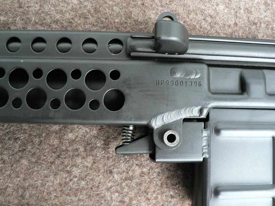
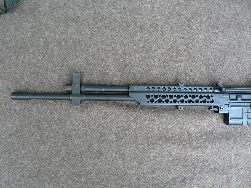
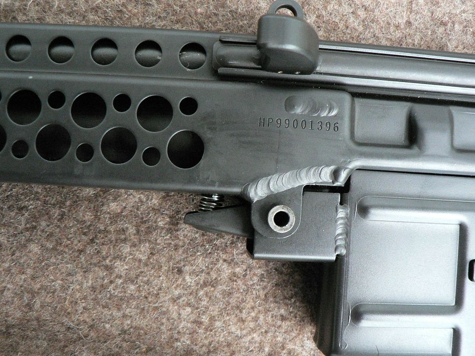
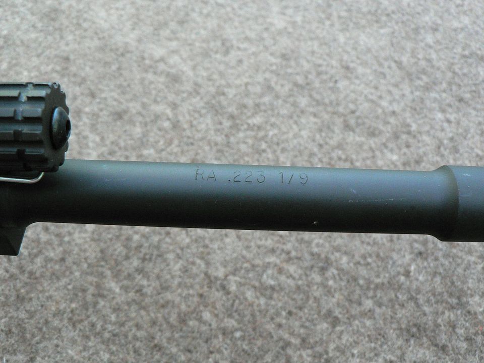
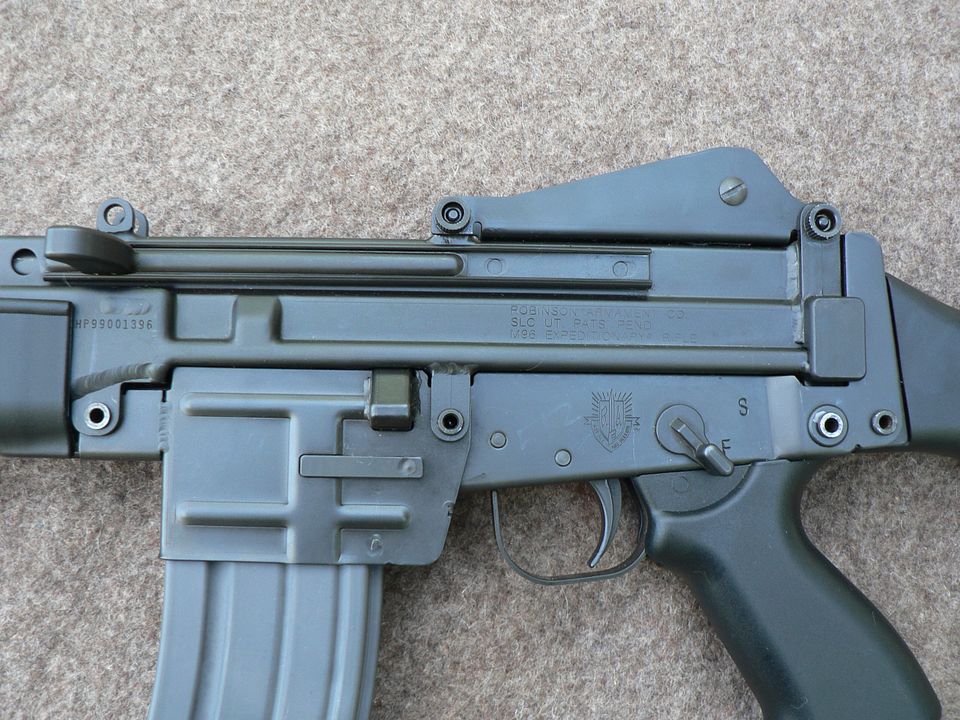
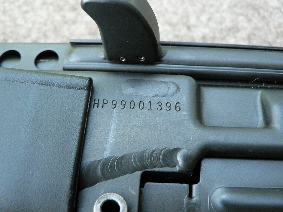
what is the serial number of this rifle? I would like to compare it with mine...Bill
Link Posted: 5/14/2021 9:31:23 PM EDT
[#3]
Thank you for the interest guys!  We'll see the serial number a bit later, most likely in the next post.


Moving on down the line, we come to to exposed front part of the gas tube up above the barrel:
 
The very front of it is a larger diameter than the main body and it's beautifully welded to the main tube.  It's knurled at the very front because you rotate the gas tube to remove it from the receiver.  We'll get to that later.  At that time, we'll also see that there is a sleeve extending from the rear of the gas block that plugs into the front of the gas tube.  

A top view of the gas tube showing two of the four gas vents:

The extremely even and smooth finish gives the impression that it's painted but it's either parkerizing or melonite.  I do not know if the gas tube is stainless steel or not.  Maybe one of you guys who is more edumacated than me can tell me the answer to that.


At the very front of the stainless steel receiver are both left and right side sling mounting rings.  This is a nice touch:


Looking at the left side sling ring from the rear, we can see that it's part of a larger reinforcement block welded to the front of the receiver:

Again, notice the outstanding aesthetics of the weld.  I dare say, as a whole, the welds on this rifle are some of the best I've ever seen on a firearm and I've seen some pretty nice welding over the years.

Next up is the plastic handguard that covers the lower part of the receiver:

You younger dudes call this polymer and RA calls it "fiber reinforced plastic".  Whatever you want to call it, the fact is it's still strong after 22 years and shows no signs of aging so it must be made of decent stuff.  It's attached to the receiver by the use of a single HK style pin.  You might think that the use of a single pin would allow the handguard to wobble/rattle around a little but it's so well form fitted to the receiver that there is zero movement.
Through the thirteen lightening/cooling holes in the receiver you can see the gas tube making its merry way back to the trunnion hidden deep inside the receiver.  On top of the receiver, you can see a couple lugs with holes in them.  In the rifle's current configuration, they are used to mount an optional picatinny rail.  If the rifle is set up in the top feed configuration, the receiver is flipped, the front lug becomes the handguard mounting point and the rear lug goes unused.  What??  It'll make more sense later when we have the rifle stripped down.


In this left side view, we see that the handguard is designed to stand off the receiver.  This allows air circulation to facilitate cooling:

Also visible is the nonreciprocating charging handle.  It is made of steel, not plastic.


A closeup of the handguard illustrating that it's made of a textured plastic to knock down on shine and give you a better grip when you have funky, sweaty hands:


At the bottom rear of the handguard is a cutout surrounding the barrel release button; the use of which we'll cover later:

We'll look at the inside of the handguard when we cover its removal later on.  


Alrighty, that's it for this installment.  Next time we'll take a general look at everything between the handguard and the buttstock.  I've got a busy weekend coming up so it might be early next week before I continue but I'll add a little more before then if I get lucky and have some spare time.
Link Posted: 5/14/2021 9:48:11 PM EDT
[#4]
Very cool! Thanks for the info.

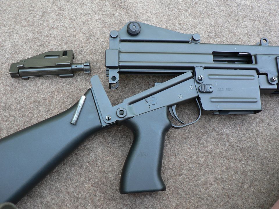
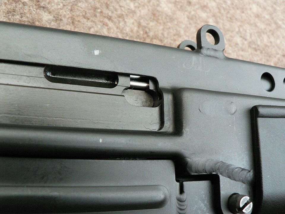
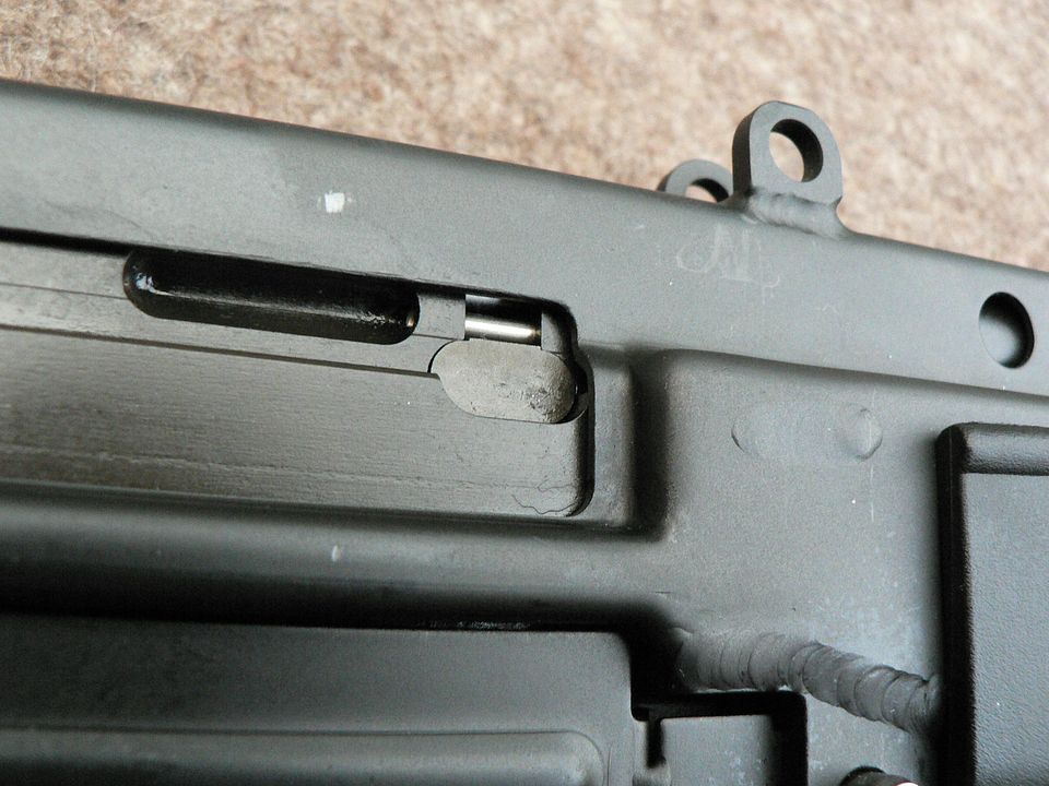
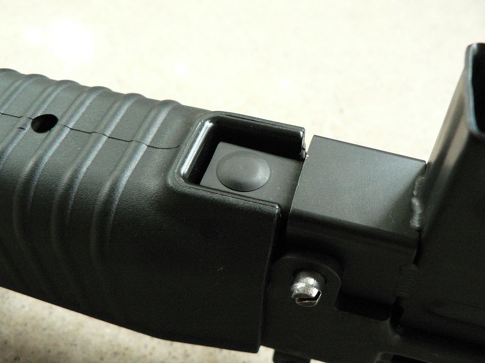
If you need pictures of the "later"* version let me know. I have the carbine barrel and the top feed (Bren) kit.

*- You claim yours is an earlier version. Mine is slightly different (gas tube, adjustable gas block, and barrel removal button). So I assume mine is a later model.
Link Posted: 5/20/2021 1:07:26 AM EDT
[#5]
As promised, we're now moving on to the main part of the receiver.  We'll start with a general look at the left side:

While this may look like one large part to you, it is actually three subassemblies pinned together to make one.  As we delve deeper into this rifle this will become clear when we disassemble the various bits but for now, just accept it when I tell you that we have the the receiver proper, the lower receiver, and the magazine well.  holding all of this together are three pins which I will call the "front", "middle", and "rear" pins.  All of these pins are removeable without the use of a special tool.  In fact, all of the pins on this rifle (there are two types) are designed to be removed with a cartridge or by simply unscrewing two halves.  

Most of the markings on this rifle are on the left side:

"SLC" is short for Salt Lake City and all rifles were marked "M96 EXPEDITIONARY RIFLE" regardless of the configuration it came in.  In the logo is the Latin phrase "AUT PAX AUT BELLUM" which translates into "Either Peace or War".  All markings are stamped  into the metal and are extremely crisp.

Also on the left side is the serial number:

The "HP" prefix tells us that the receiver was partially manufactured by another company, which I'm pretty sure has not been identified, and then finished up inhouse by Robinson Armament.  Later rifles had an "RA" prefix meaning it was entirely manufactured by Robinson.  "99" is the year of manufacture and the rest is the actual serial number.  HOWEVER, Robinson started their serial numbers at 500 which means that this is NOT the 1396th rifle but rather the 896th one made.  Got it?  I hope so.  Above and below the serial number are two of the welds holding the machined trunnion into the stamped receiver.  Again, just beautiful welding.  


Here, we see the charging handle and bolt pulled to the rear exposing the long stroke gas piston:

We will look at all of this much closer once we've disassembled the rifle.


On the right side of the receiver, we find the ejection port:

In front of the magazine release button we see ".223 REM" as the caliber.  Although it's not marked anywhere, my understanding is that you can also use 5.56 NATO rounds without a problem.  You have to remember that this was made during the Slick Willy ban years so marking them as being capable of shooting a NATO round may draw unwanted attention from libtards and idiots.  
Also notice that there are "F" and "S" markings but the safety is not ambidextrous.  There is a tick mark on the safety axle though so that you know whether you are set to "Fire" or "Safe".


Looking at the bottom of the pistol grip, we see that it's hollow and held on by a button head socket cap screw:

Before you go meddling with this screw to change out grips, be aware that I'm pretty sure this also holds the spring and detent for the safety in place so if I were you, I wouldn't go screwing around with this!  <-----  See what I did there?  


Sitting atop the receiver is the two position, flip rear sight protected by two ears.  It's shown here flipped forward to the 100 yard setting:


Flip it back and your are on the 500 yard setting:


Although the front sight is windage adjustable, that is only designed to initially zero the rifle.  At the range or in the field, practical windage adjustment is done using the rear sight.  This is acomplished by using the windage knob on the right side of the sight:

This looks to me like it's taken straight off of and interchangeable with an AR15A2 rear sight but I may be wrong.  It sure wouldn't be the first time!  Anywho, each click clockwise should move the point of impact to the right approx. 1/2" at 100 yards.  

On the rear sight base are a number of hash marks and a corresponding mark on the flip sight when set to the 500 yard setting:

When initially zeroing the rifle, the idea here is to first align the mark on the rear sight with the center hash mark on the base.  Then, using the front sight screws, adjust the windage so that the shots are centered with respect to left-right on a target setup at 100 yards.  Then flip the rear sight to the 100 yard setting and adjust the front sight post up or down until the shots are centered on the target.  Done.


Here, we see the left side of the rear sight assembly:

The slotted screw is the head of the windage axle.  Don't mess with that.  Forward and rear of this screw are to round thingees that look like wheels on a toy car.  These are the pins that hold the rear sight assembly on the receiver.  

A left side detail shot of the rear pin:

This is a two part pin that is designed to simply unscrew for removal.  Unfortunately, both of the pins on this rifle have seized with age so I can't remove them to show you.  I've tried penetrating oil but that hasn't worked.  I'm sure I could go all bubba and use pliers to remove the pins but that would no doubt destroy the fine fluting we see so we're just going to leave these little pins alone.  They've been happily doing their thing for 22 years now so I'm just going to channel my inner BoB RosS and leave this happy little accident as it is.

A detail shot showing the right side of the pin:


An finally, the front pin in situ:


That's it for tonight.  Next time, we'll look at the butt stock.  Until then, have some fun, turn off your TV, and play with your Dog instead.  You'll be glad you did, I promise you!
Link Posted: 5/20/2021 1:17:31 PM EDT
[#6]
Very cool!

I always wanted one but they either eluded me or were too cost prohibitive.
Link Posted: 5/20/2021 4:14:49 PM EDT
[#7]
This was on my list to acquire 20 yrs ago but didn't.  However, there might be a slim chance now that Rob Arm is resurrecting the M96 Expeditionary Rifle - https://robinsonarmament.com/m96/
Link Posted: 5/20/2021 4:34:42 PM EDT
[#8]
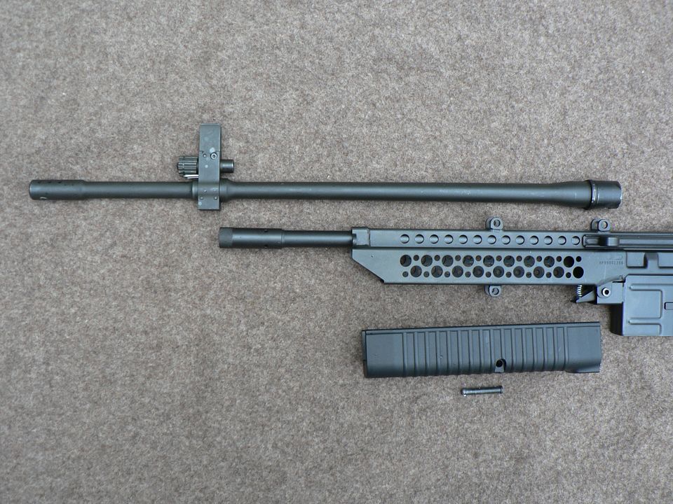
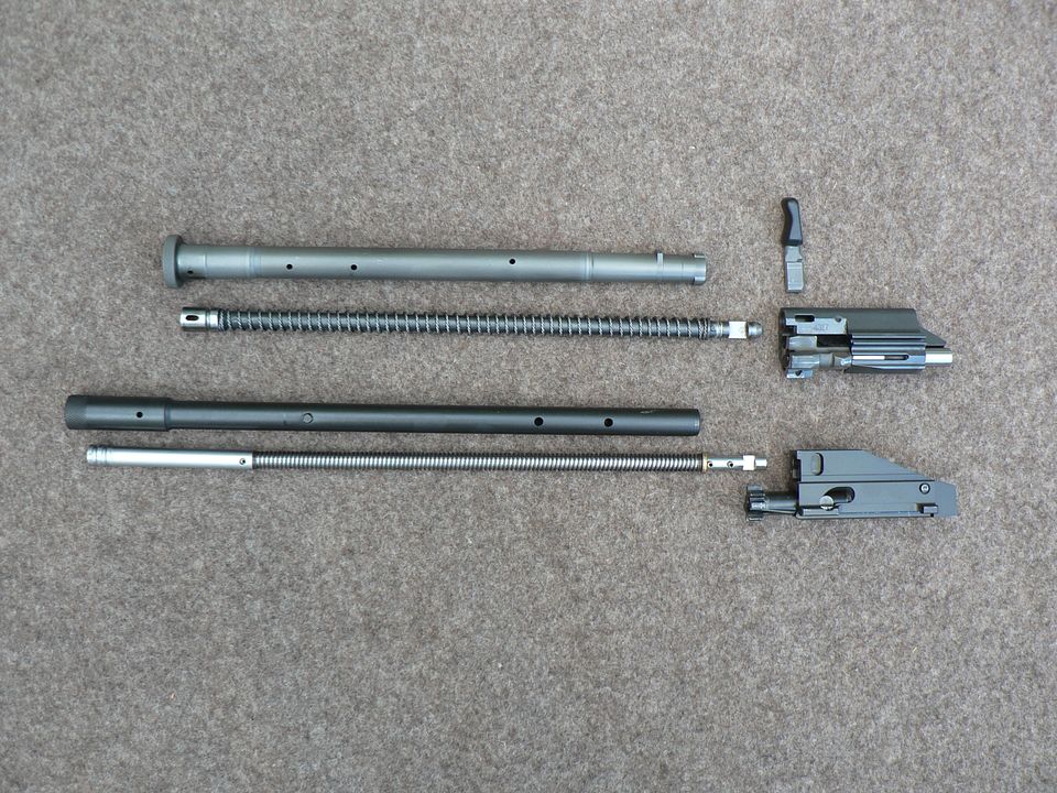
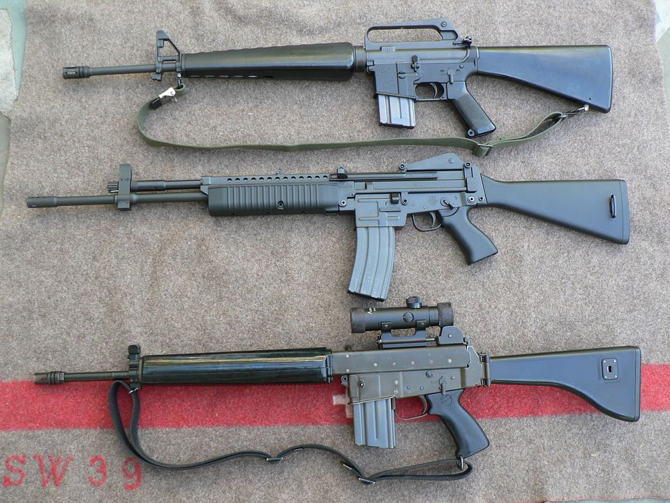
Let's just say I had a thing for them, back in the day. Had three; the rifle, the recon carbine, and the top loader. started off buying accessory barrels and such, eventually just bought additional complete guns. They never did ship the promised belt fed version.

Eventually sold them all for way more than I paid for them and bought another M16.

Some pics from way back when:

Attachment Attached File

Attachment Attached File

Attachment Attached File

Attachment Attached File

Attachment Attached File

Link Posted: 5/21/2021 9:55:01 PM EDT
[#9]
That Bren configuration is darn nice.

Ka
Link Posted: 5/22/2021 6:30:37 PM EDT
[#10]
Did they bail on making new ones? If so I am going to buy an old one.
Link Posted: 5/22/2021 7:31:18 PM EDT
[#11]
Discussion ForumsJump to Quoted PostQuote History
Quoted:
Did they bail on making new ones? If so I am going to buy an old one.
View Quote


I was in the same boat. Got tired of waiting and jumped on a NIB recon carbine on gunbroker. Prices are going up and wouldn’t be surprised if/when the new ones come out the price is higher then originally thought.
Link Posted: 5/23/2021 12:58:25 PM EDT
[#12]
Nice! I had one about 10 years ago, sold it, now I regret it, lol.
Thanks for sharing
Link Posted: 5/24/2021 4:04:47 PM EDT
[#13]
Time to take a look at the buttstock.  Here it is:

Next up is.......nah, just fooling about.  Of course we're going to take a close up look at it.  It's plastic, or as RA calls it, "Fiber Reinforced Plastic".  That makes is sound more exotic, doesn't it?  It's just plastic but it seems to be pretty sturdy so I'm assuming it's made of good quality stuff.

As you can see from this rear view, it's fairly slender but the dimensions are right because it shoulders nicely and your your eye goes right to the sights:
 
The picture makes it look like the rifle is bent, the stock is wonky, and the rear sight is crooked but that's an illusion created by my poor photographic skills.  In truth, everything is straight and true.

Here's a left side oblique view showing the ribbed plastic butt plate and the pressed steel sling mount:


And the right side showing that the sling mount extends all the way through the stock:

Part of the reason for the sling mount passing all the way through the stock is reinforcement but the main reason is so that it can be switched from side to side to suit the owner's preference.  

All you need do is pull out the pin at the rear of the stock:


Pull the sling mount out of the left side:


Stick it back in the right side:


Push the pin back in and BLAMMO, you're done:


Here's a closeup of the components:

Notice that the pin looks very much like an HK pin.

In fact, it's a direct copy with regards to design:


Dimensionally, it's a larger diameter and longer than an HK handguard pin but smaller in diameter and shorter than an HK stock pin.  


To remove the butt plate, pull out both the pin and the sling mount.  Then, the butt plate pops right off with minimal effort:

You might think that the butt plate would wobble a bit but that's not the case.  Everything is a tight fit when assembled.  Not that it matters but the butt plate has an up and a down side.  If you try to install it upside down, the sling mount won't fit so it's pretty much idiot proof.

The stock is completely hollow:

All you can see up in there is a single nut that holds a steel reinforcing plate in place where it attaches to the lower receiver.  We'll see that plate in a bit.  The smooth shiny plastic creates a funhouse image of the nut.....neat!
Link Posted: 5/24/2021 4:44:49 PM EDT
[#14]
Alrighty, it's time to start taking things apart.  Since we're back here already, we'll start with removing the stock.  If you remember the beginning of this article, I said that the M96 was designed to be modular.  One of the modular design features was the ability to switch out the solid stock for a folding one although I'm pretty sure one was never actually offered.  But hey, it's designed to come off so we're going to take it off.

You start by removing this pin:


Looking at the top front of the stock, we see that it has a steel tongue sandwiched between the rear wall of the lower receiver and a bar which is also part of the lower receiver:

You have to disengage the steel tongue and you do so by pushing the front stock down about a 1/4":

Be aware that the stock is a vert tight fit so you may have to use a mallet, at least I did.  DON'T BEAT ON IT and DON'T USE A HAMMER!!  I placed a folded up cloth on the top front of the stock and used a rawhide mallet to GENTLY tap the stock down.  

Next, you swing the stock upwards.....:


And away from the lower receiver:

When you put it back together, it'll fit between the ears at the back of the lower receiver easy enough but you'll most likely have to use the mallet again to GENTLY tap the stock upwards into the seated position.  Tap at the front bottom of the stock until the holes line up and then reinsert the pin from either side.  One of the problems with these rifles is that the pins are very tight when new and you will probably need to use a punch or some similar object to remove and replace them until they wear in.  If you are careless about what that object is, you'll mess up the finish on the pin heads.  As you look at the various pictures of this rifle,  you'll see just what I am talking about.  Clearly, someone in the past was a little careless when removing some of them.  Don't be that guy.


Here is the steel reinforcement plate at the front of the stock that we talked about earlier:

On the other side of this socket head screw is the nut we saw up inside the stock.


With the stock removed, we can see the rear of the lower receiver:

Note that the ears the stock fits between are two layers of laminated steel for strength.


Next time, we'll remove the lower receiver and check it out a bit.  See you then!
Link Posted: 5/24/2021 8:44:52 PM EDT
[#15]
Great posts, thank you.  

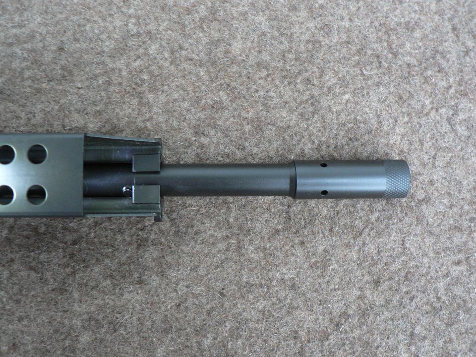
I have a 16" Recon with green furniture...been considering having the barrel turned for threads and Forward Controls Stoner-63 style flash hider added.  I don't think it would hurt resale as who would want a ban-era drilled brake vs. options but who knows (maybe it would).

A guy I chat with on some other groups did a folding stock for his, using spare Stoner 63 parts (which are rarer than M96's).
Link Posted: 5/24/2021 8:59:32 PM EDT
[#16]
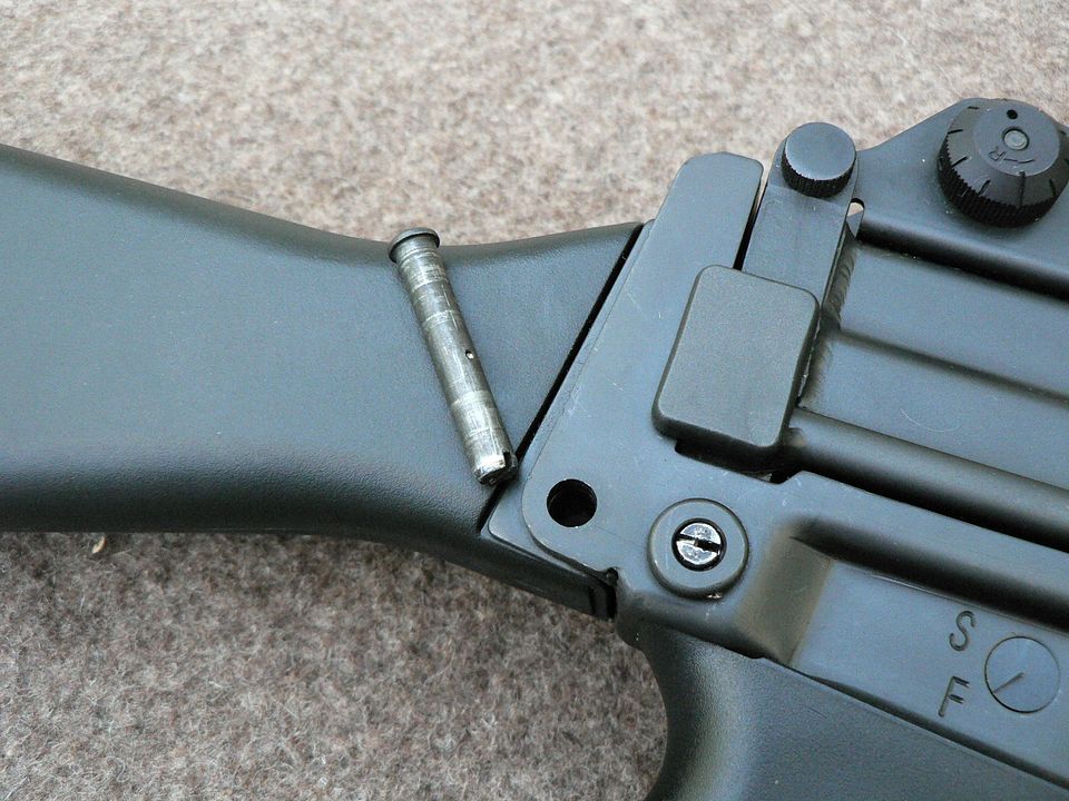
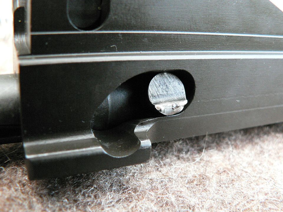
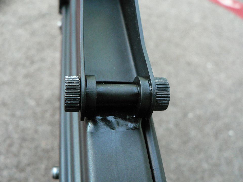
Personally, I wouldn't mess with it.  Hell, I almost didn't buy this one because of the aforementioned messed up finish on some of the pins.  The first rule of collectable rifles in my mind is to leave it as it is.
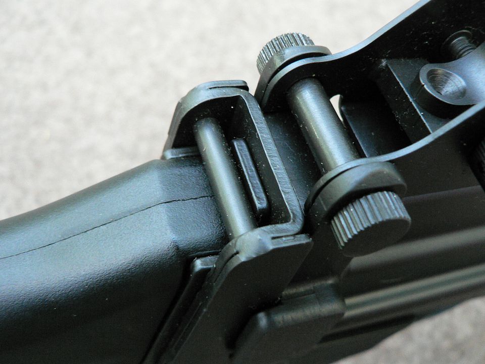
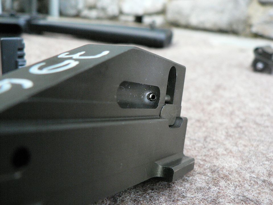
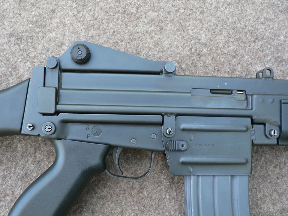
Link Posted: 5/27/2021 11:48:42 PM EDT
[#17]
In this installment, we're going to remover the lower receiver and take a look at it.  Before we do that, we have to charge the rifle to cock the hammer which would seem straight forward BUT READ THE FOLLOWING FIRST.

The safety can be applied regardless of whether or not the hammer is cocked.  YOU MUST NEVER PULL THE CHARGING HANDLE TO THE REAR IF THE HAMMER IS NOT COCKED AND THE SAFETY APPLIED.  If you do try to pull the charging handle to the rear with the safety applied and the hammer is not cocked, you will meet strong resistance after just a short distance.  If you continue to pull the charging handle to the rear by forcing it you WILL BREAK THE TRIGGER.  You may pull the charging handle to the rear without damaging the rifle with the safety applied and the hammer is cocked.  If you are unsure whether or not the hammer is cocked and you wish to pull the charging handle to the rear, make sure the selector is set to the "F" (FIRE) position.  My personal recommendation is that you err on the side of caution and charge the rifle only when the selector is in the "F" (FIRE) position.

Alright, with that sufficiently beat into your head, let's begin.  To remove the lower receiver:
1.  Set the selector to the "F" (FIRE) position.

2.  Pull the charging handle fully to the rear and release it.  

3.  Set the selector to the "S" (SAFE) position.  <----- THIS IS IMPORTANT.  DO IT.

4.  Remove these two pins.  If they are tight, use a nonmarring tool such as a wooden dowel rod to press them out:


5.  While supporting the rest of the rifle, pull the lower receiver down and to the rear, separating it from the rest of the rifle:


The lower receiver shell is made of two stamped stainless steel halves which are then welded together.  Here, we can clearly see the weld seam in front of the trigger guard:

If you look closely at the above, you can also see the seam between the trigger guard and the trigger.  The trigger guard is a separate stamped part.  


Looking down into the lower receiver we can also clearly see where the two halves meet:

The reason it's so much easier to see from the inside is because it was welded from the outside and then (I assume) ground smooth.  Or maybe the weld is just that good, I don't know.  Whatever the case, it's extremely well done.  

Let's talk about the finish on this rifle for a second.  Robinson Armament lists the finish as "Hard Matte Black" which doesn't really tell you much.  My research has come up with varying and sometimes conflicting answers as to the finish so I'm not going to say what it is......because I truly don't 100% know.  Some of the parts appear to be phosphated and some of them look to be blued.  But the large majority of the rifle has an extremely tough matte black and smooth finish that reminds me of the ferritic nitrocarburizing used on older Glocks.  That finish is also known as "tenifer" and "melonite" among other things and I HAVE read that it was the finish used on the M96 but I cannot claim that to be a fact.  So, I'll just leave the judgement as to what it really is to others and describe the finish as matte black, smooth and extremely durable.

Earlier, I pointed out the importance of applying the safety before removing the lower receiver.  That's because pulling the trigger and allowing the hammer to fly when the lower receiver is removed WILL damage the rifle.  Take a look at this picture:

What you are looking at is what the hammer uncocked and resting against the front face of the lower receiver.  The hammer spring has quite a bit of force and slamming the hardened steel hammer into the thin stainless steel receiver shell repeatedly will eventually either crack the shell, snap the hammer off where it impacts the receiver, or end up doing both.  The moral of this story is, don't dry fire an unassembled M96 rifle.   On a positive note, notice how nice and neatly welded in place that little square piece of steel is.  


Here, we see the front of the hammer in the cocked position:


And here is the rear of the hammer uncocked:

You can see a seam line telling us the part is either cast or forged.  Personally, I don't like to see stuff like this, preferring machined but I didn't build it so I don't get to make that call.  The square block sticking out the side of the hammer is where it's grabbed by the sear and disconnector.


A detail shot with the hammer uncocked showing the trigger/sear and disconnector:

Front is to the left.  Notice that the hammer and trigger employ separate springs.
On the right side directly behind the hammer spring is the sear which is cast/forged as part of the trigger.  When you charge the rifle, the hammer presses on this sear which slightly rotates the trigger from the resting position thus moving the sear out of the way.  As the hammer passes the sear, the trigger spring rotates the trigger/sear back to the resting position thus holding the hammer in the cocked position.  This slight rotation is exactly why you cannot have the safety on when you charge an uncocked rifle because the safety locks the trigger tight preventing any rotation.  So when you gorilla the charging handle to the rear without the hammer cocked and with the safety applied, ALL of that force is being placed on that tiny little sear surface.  I guarantee you that even the weakest of us can pull the charging handle back harder than that sear can take.  

In this shot, we see the sear and disconnector from a slightly different angle:

Front is in the upper left hand corner of the photo.  Again, we see the sear directly behind the hammer spring but from this angle we can see the beveled surface that the hammer presses against as it rotates to the rear.  Behind the sear, we see the disconnector.  It shares the same axle pin as the trigger/sear and you can just make out the disconnector spring at the rear of the disconnector.  


Here, we see the selector drum set to "S" (SAFE):

Front is at the top of frame.  On the left side of the drum, you can see a slot machined out of it.  This interacts with a bar projecting back from the rear of the trigger.  Pulling the trigger rotates the bar upward.  In it's current position, the selector drum slot is out of alignment with the trigger bar so the trigger cannot be pulled.  When the selector is set to "F" (FIRE), the slot on the selector drum is in proper alignment with the trigger bar and so the trigger can be pulled.  Simple mechanics.  
In the center of the selector drum, you can see a shallow channel with a detent projecting into it.  This is detent is spring loaded and held in place from below by the pistol grip screw.  It's purpose is two fold.  First, it limits the travel of the selector drum.  Second, it locks the selector drum into whichever mode you select, SAFE or FIRE.


And with that, we are finished with the lower receiver.  Now you know the basics about how it's made and how the fire control group on an M96 works.  I could completely rip the thing apart and go into outlandish detail about every little aspect of it but I really don't feel like doing that and I get the feeling that almost nobody out there wants to plod through all of that anyway!  So, bye for now and we'll take a look at the magazine well next time.
Link Posted: 5/28/2021 12:35:31 AM EDT
[#18]
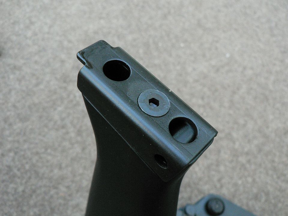
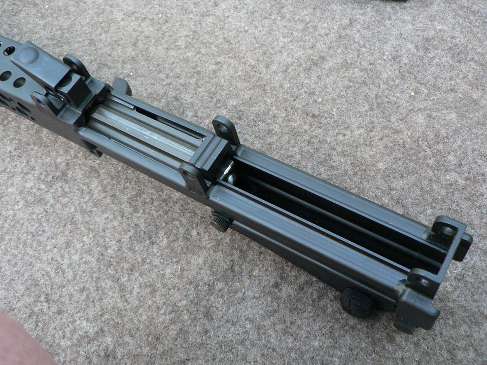
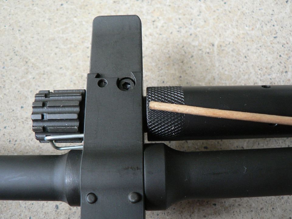
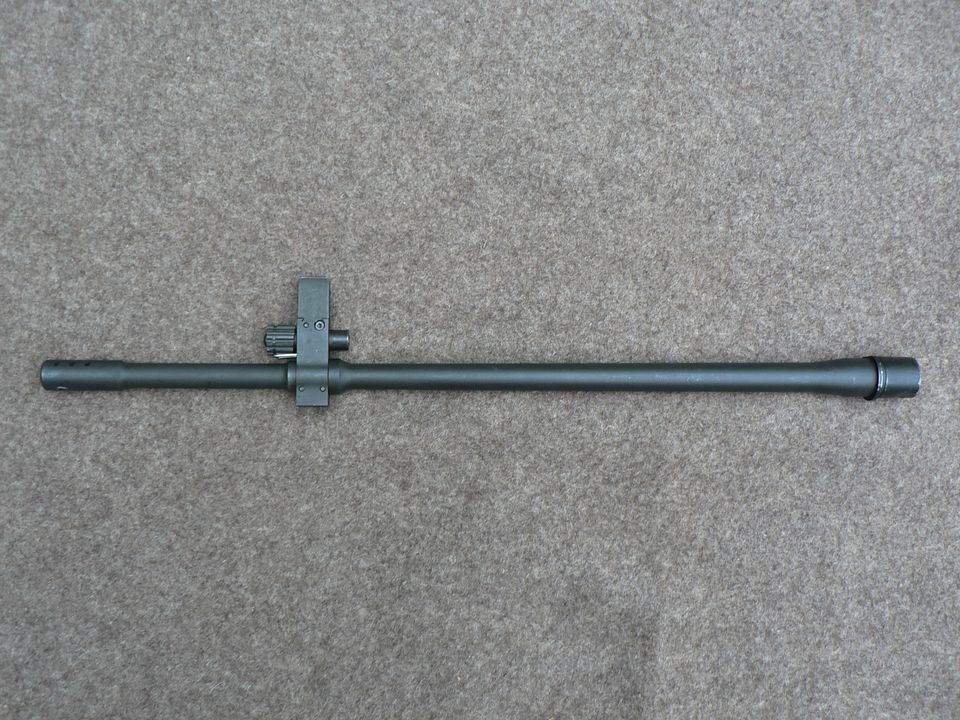
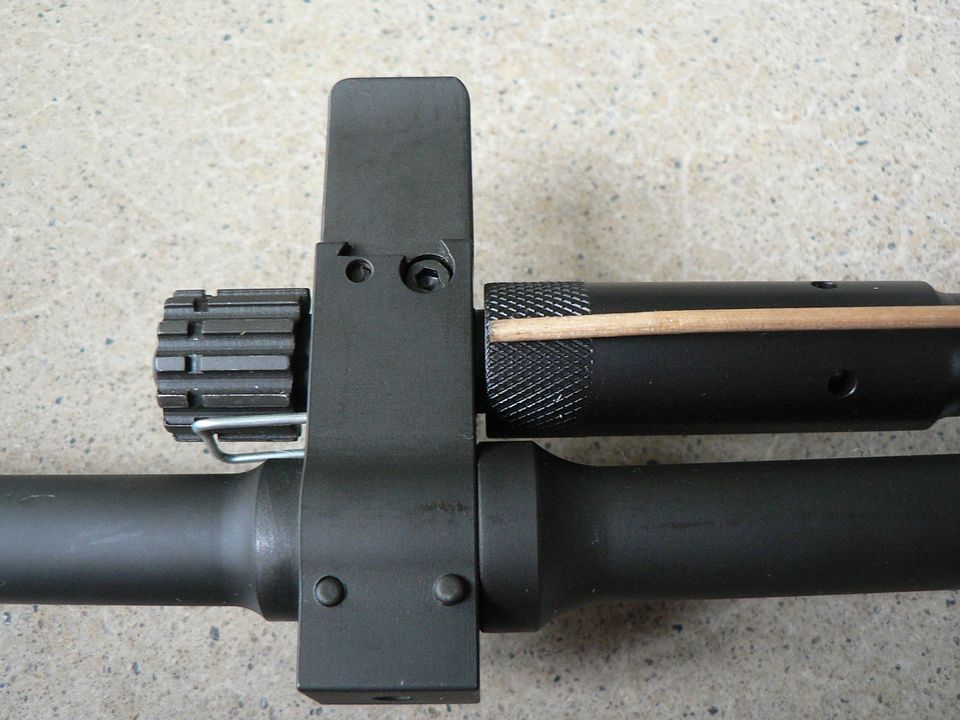
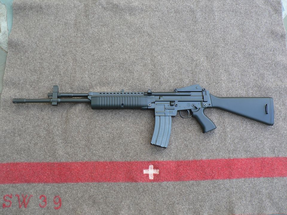
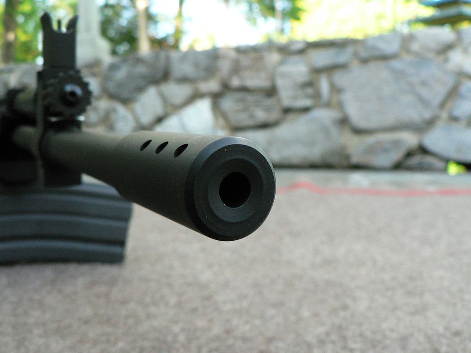
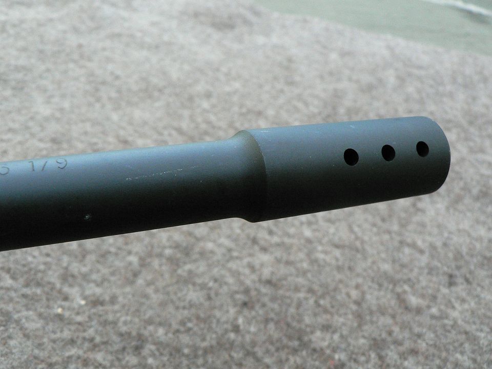
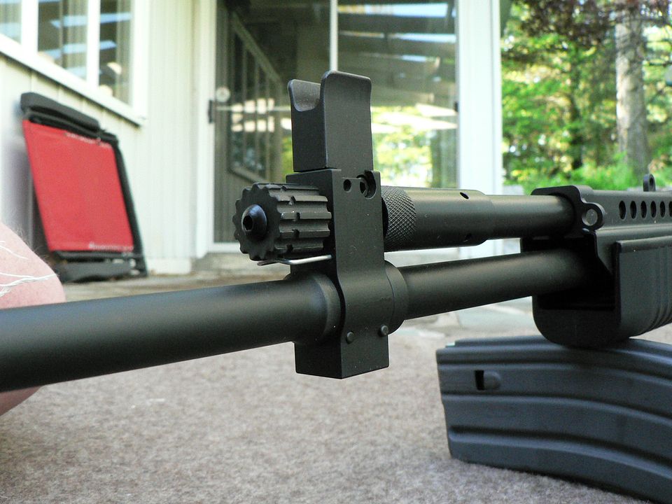
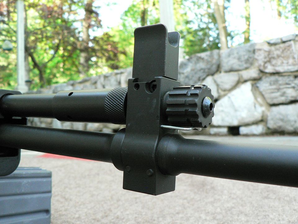
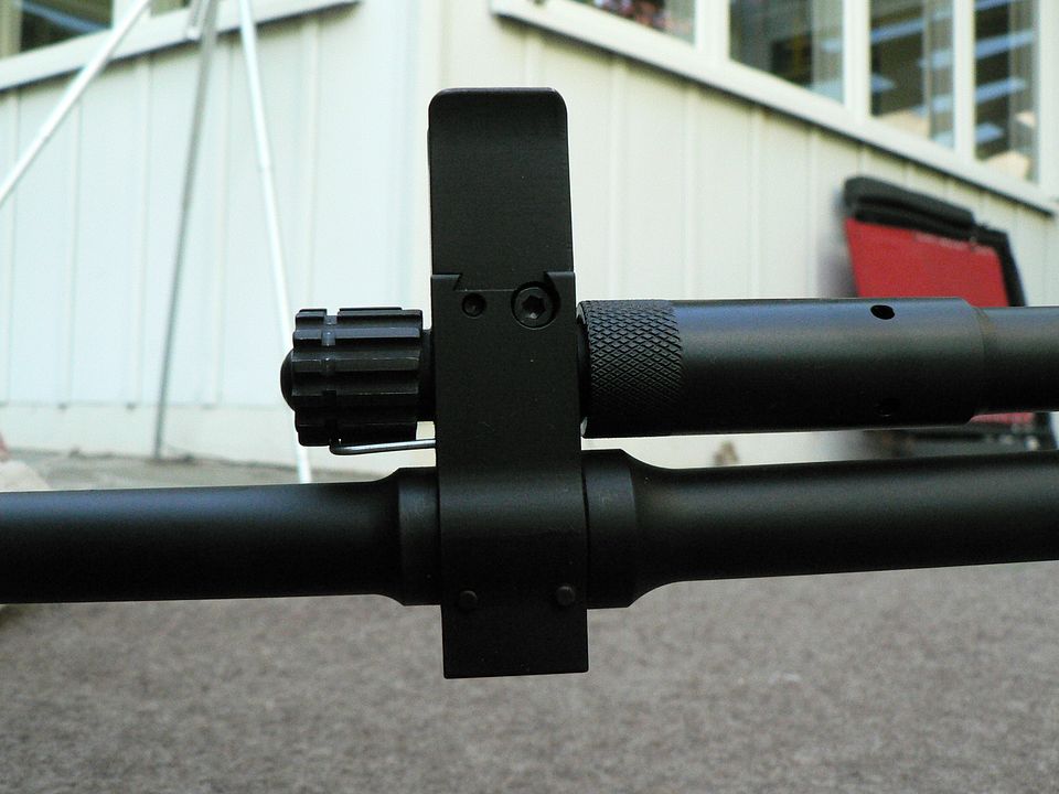
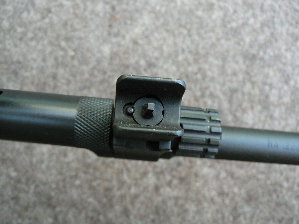
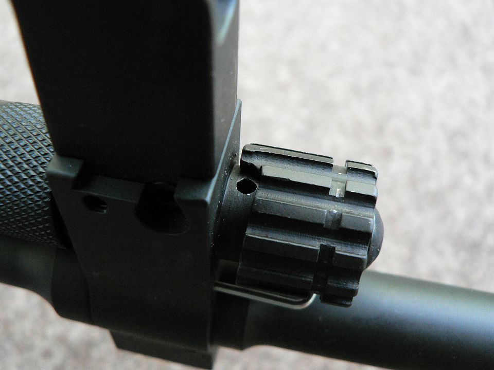
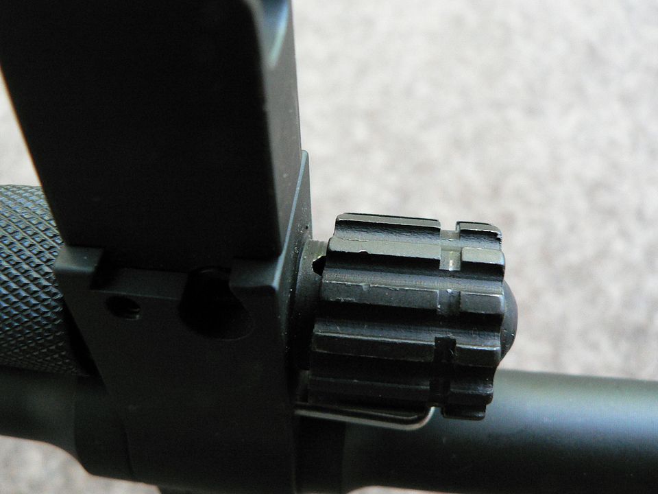
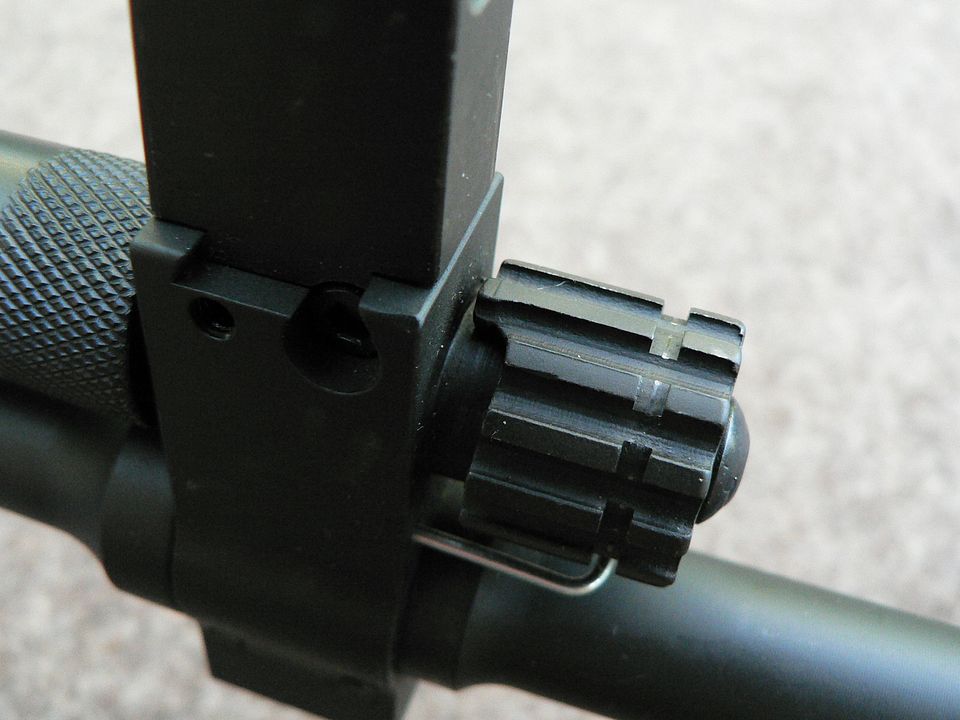
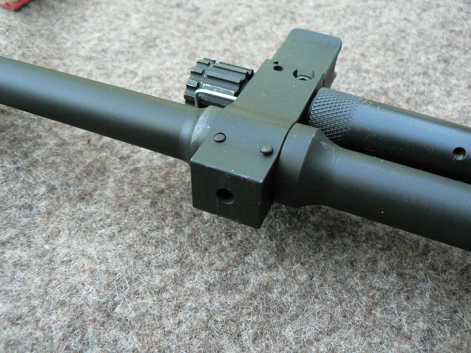
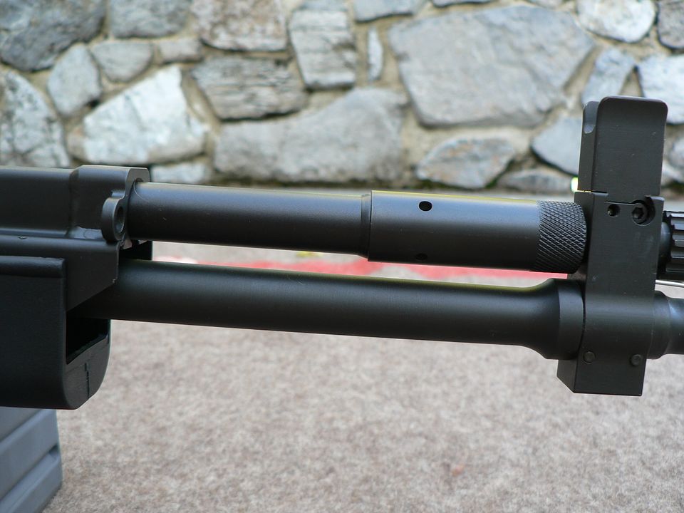
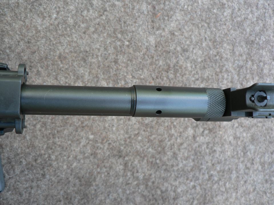
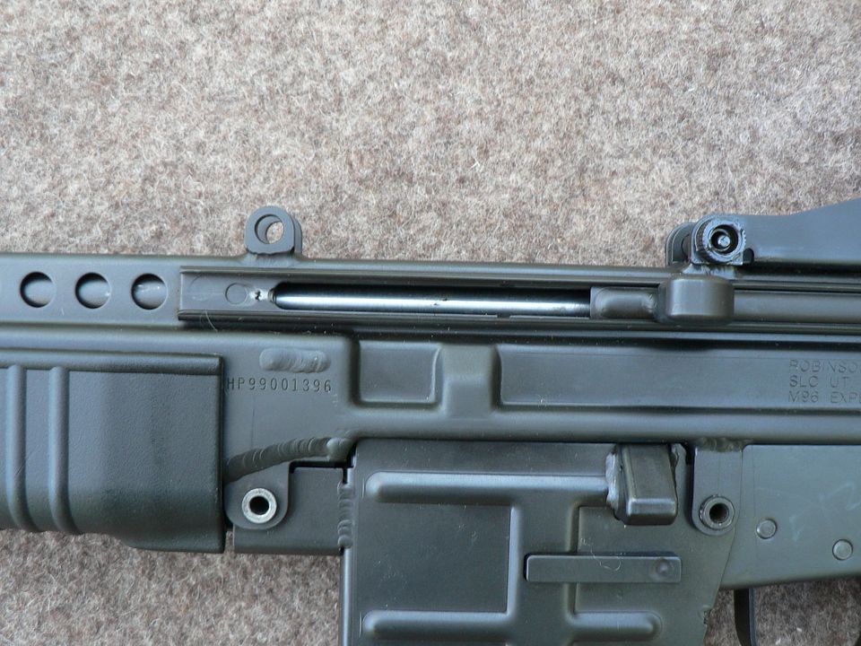
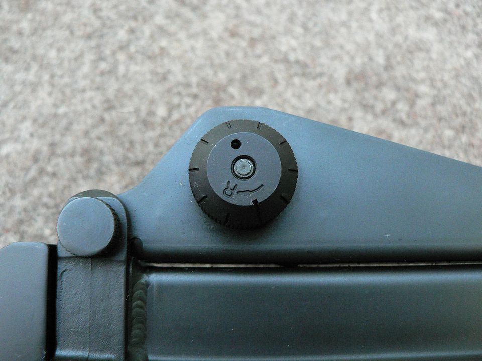
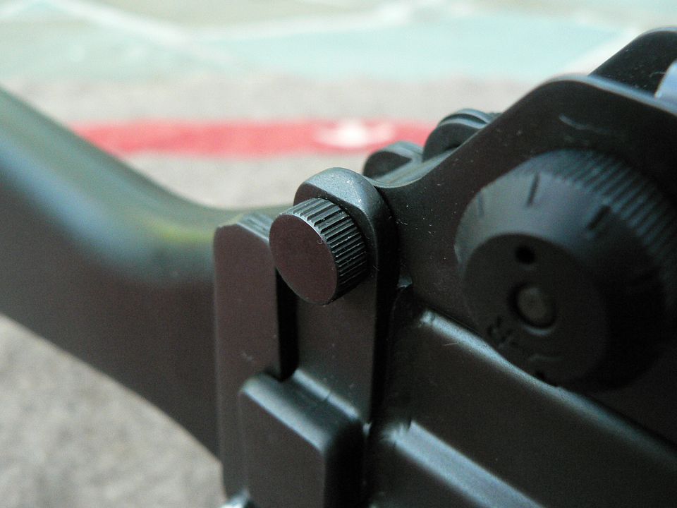
Yours has the old style gas adjustment knob. They did put out another one. I have it in my gear. It has holes, not the ramp.and is smoother, It doesn't have the bulldozer tread style grip to it. I will see if I can dig it up this weekend. If you shoot it, put VC3 on every thread. I rang mine out like a spotted ape.
I just noticed the Bren pic has a smooth one on the 20 inch barrel.
Link Posted: 5/28/2021 12:41:48 AM EDT
[#19]
Considered buying one about 2000, was really interested in the Bren Gun version.

No doubt, would have been a great investment.
Link Posted: 5/30/2021 10:57:56 PM EDT
[#20]
Next up is the magazine well.  On the M96, it's removeable.  It's removeable because the rifle was designed to be modular and a belt feed mechanism was planned.  In belt fed mode, the receiver was flipped upside down a magazine well sticking out of the top of your receiver kinda' gets in the way of a belt feed mechanism.  But, as already stated, Robinson never offered that setup and so, for all practical purposes, there is never going to be a reason to remove your magazine well.  Just the same, it comes off so we are going to remove it.  Let's have at it, shall we?

This is dead simple.  The first thing you need to do is remove these two pins:


Next, you simply pull the magazine well down and away from the receiver:

The magazine well can be removed with or without the lower receiver in place.


Now that we've removed the magazine well, let 's examine it a bit.  Like the lower receiver and the receiver proper, the majority of it is made of stamped stainless steel components.  There is also a machined steel component that serves both as the rear wall of the assembly and as the mounting point for the bolt hold open and ejector.  
Here is the left side of the magazine well:

it has reinforcing ridges stamped into it for rigidity and they do their job because the body of this thing will not flex no matter how hard I squeeze it.
The horizontal bar you see about midway up is the magazine catch.  
Above the rear of the magazine catch, you can see something sticking out.  This is part of the machined component and it houses the spring loaded ejector.  We'll look at that a bit closer in a moment.
There is a button weld seen at the bottom rear which holds the sheet steel to the machined component.  It's also welded in front of and behind the ejector housing.


Here's the right side:

Other than the magazine release button, there isn't much to see here.  Although the button may look like plastic, it is metal.  Notice that there is no bolt release.  While the rifle does have a last round hold open, the only way to release the bolt is to pull the charging handle to the rear with either a loaded magazine inserted or no magazine at all.  Later versions of the rifle did incorporate a bolt release.
The two weld marks in front of the magazine button and below each of the reinforcement ribs are button welds attaching the sheet metal to the machined steel component.


The front showing a reinforcement rib:

About midway up, you can see the "U" shaped extension which serves as the mounting point for the front pin.  It's welded to the magazine well along all three sides of the "U".

Here's an oblique view of the extension which should make what I'm describing above a bit more clear:


Rear view of the magazine housing:

Starting at the bottom, we see a little piece of sheet stainless welded in place to act as a stiffener and dust cover.  When assembled to the rifle, the front of the lower receiver plugs into the magazine well and the bottom of the lower rides along the top of this stiffener/dust cover.  Although I didn't take a picture of it, this bit curves under the magazine well assembly and terminates where it meets the rear of an inserted magazine.  
Continuing upwards, we come to the magazine release spring wound around the magazine release transverse bar.  
Above the magazine release spring, we come to the machined component.  As we will see in a moment, this part runs the entire height of the assembly.  
Sticking out the left side is the roughly triangular ejector housing.  Notice that the machined component has two roll pins.  One holds the ejector in place and the other holds the bolt hold open in.

Here's an oblique rear view that should add clarity to the above description:


Looking down into the rear of magazine well from above, all of the "machined component" talk should now make perfect sense:

It's one part that serves multiple roles.  It's the rear wall of the magazine well and it's a solid bit perfect for attaching the spring loaded ejector and bolt hold open.  But perhaps it's most useful role is that it adds rigidity to the entire assembly.  Everything is essentially built around this part.  


A rearward looking photo showing the front of the ejector and the bolt hold open in the down position:

The ejector is spring loaded and is forced down into its housing by the bolt carrier as it rides home.

Rear detail shot of the ejector:


Empty magazine in place illustrating the bolt hold open in the up position:


Bottom of the receiver with both the magazine well and lower receiver removed:

Front is to the left of frame.  If the top feed configuration was used, this would become the top of the receiver.  The magazine well would still be used in the same place but the new offset rear sight would be pinned in place where the lower receiver had been.  On what would now become the bottom of the receiver, the now useless rear sight would be removed and the lower receiver pinned in its place.  Groovy, huh?


The last thing I want to talk about in this installment is one of the downsides of the M96.  That is the fact that pinning everything back together can get fidgety real fast.  
Take a look at this picture:

What we are looking at is the intersection of the receiver proper, the rear mounting hole on the magazine well, and  the front mounting hole on the lower receiver.  All of these things need to lone up perfectly or that pin just is NOT going to go in.  You can't have the holes oversized or the various parts will rattle around and it'll pall apart in use.  Now I've handled a Stoner 63 and it can be a little bit of a pain lining this stuff up too but it's WAY easier to get together than this thing.  The good thing is that it does get a little easier with familiarity and use but it's never going to be as slick as an HK or the MarColMar CETME L.  To be honest, the way the various parts pin together cheapens what I otherwise consider for the most part to be a very nicely built rifle.  I mean it feels like five miles of gritty road pushing these pins home.   I know it can be done because the Stoner pins glide in like butter.


The front pin is even more fun because we've added another thing that needs to be lined up (barrel release button) and it's even spring loaded as a bonus:

Here, the pin first passes through the mounting lug welded to the receiver, then through the front hole on the magazine well, then through the barrel release button, and into a hole bored through a lug on the bottom of the trunnion before exiting out the other side through the same components in revers order.  Why they didn't put a non-removeable sleeve in there to keep the barrel release button permanently affixed to  (and thus aligned with) the lug on the bottom of the trunnion I'll never understand.  But I guess it's kind of a mot point because, as I said earlier, there is no real reason to ever remove the magazine well because Robinson never made the belt fed bits.  


That's it for now.  We'll remove the handguard and look at it next time.  See you then..
Link Posted: 6/6/2021 4:29:11 PM EDT
[#21]
It's been a bit but, as you are aware I'm sure, life has its own ideas about what you are going to do with your time!  Anywho, I'm back at it and we're going to take the handguard off.

 Like thee magazine well, there's not much to it.  Just press out the single pin:


And pull it straight down and off the receiver:

You might have to rock it front to back a little bit to get it off because it's a tight fit.  But a tight fit is a good thing because it means that it doesn't wiggle around when mounted.  There are lots of interesting things to see on the receiver in this picture but we'll save all of that for later once we have everything disassembled.  For now, we're just focusing on the handguard so hold your horses Francis!


Looking at the bottom (rear it to the left) we see that the grasping ribs wrap the whole way around:

The square cutout for the barrel release button is nicely molded and there are several holes running along the bottom.  Whether they are meant for cooling or as mounting points for your favorite "tacticool" rail, I do not know.  You can also see the mold line running up the middle.


Flipping it over now to get a look at the inside:

There are no steel reinforcement bits molded or riveted into the handguard but there are several transverse ribs formed during the molding process that serve as stiffeners.  These ribs also form fit the handguard to the receiver ensuring a nice snug fit while allowing cooling air to circulate.  
If you're wondering whether or not it's flimsy, it's not.  The plastic is stiff enough that there is minimal flex but not so hard as to be brittle.  In short, it does its job just fine.

The mounting pin passes through just behind the middle reinforcing rib so there is extra plastic in this area to prevent cracking:


Well, that one was short and sweet.  Next time, we'll remove the bolt assembly and see what makes that tick
Link Posted: 6/7/2021 3:14:00 AM EDT
[#22]
I would like one of these chop off the muzzle break get a Stoner copy flashider then cut down the mag well add the rear sight with holes in it change out the fsb/gas block I know someone who did this even added a real stoner folding stock what possibilities using ar15 mags too.
Link Posted: 6/19/2021 3:16:26 PM EDT
[#23]
In this post, we're going to remove the bolt group and take a look at it.  Let's get started.

To remove the bolt, we start on the right side of the rifle at the ejection port:

Currently, the bolt is closed.  On many rifles, you simply pull the charging handle to the rear and the bolt group falls out the back of the receiver.  With the M96, you first need to disconnect the bolt assembly from the gas piston.  How do we do that?  Read on my good man.

On the side of the bolt carrier, we see a little tic-tac shaped thingamadoodad:

That thingamadoodad is actually a button.....the button we press to disconnect/disassemble the bolt carrier from the gas piston.  We will call it the "disassembly button"  or simply "button".


So, using a non-marring tool, press in and hold the button:


While keeping the button pressed, use the non-marring tool to pull the bolt carrier to the rear a ways:

It is now free of the gas piston and you can release pressure on the button.


The bolt group will now fall out the back of the receiver:

Where in the hecks is the recoil spring??  It's wrapped around the gas piston and we'll see it later.  Notice that there is something shiny in the top front corner of the ejection port.  That's the rear of the gas piston.


Before we go pulling it apart, let's take a look at what we've got.  We'll start with the right side:

Front is to the right.  The bolt is currently in the unlocked position.  Although we can't currently see it, the firing pin spring is pressing against the rear of the bolt.  If we were to press on the bolt face, it would move backwards into the bolt carrier and rotate into the locked position.  But as soon as we stopped pressing on the bolt head, the firing pin spring would push the bolt forward into the unlocked position again.  
Moving our ever inquizitive gaze rearward, we come to the tic-tac button we pressed in to release the bolt group from the gas piston.  Below the button is one of four guide lugs/rails (two per side of the carrier) that runs in a slot formed as part of the receiver pressing.  
Directly above the button is a little shiny bit.  This is a roll pin that holds the disassembly button and its spring in place.  
The cavity above the roll pin is necessary for fitment of the disassembly button.  That will make more sense when we look at the front of the carrier in detail later.
Directly behind the roll pin is a long oval area machined into the carrier.  While this could probably be considered a lightening cut, it's main purpose is to allow the roll pin to be removed or inserted should you need to service the disassembly button.
Continuing to the rear, we come to a little circle near the rear of the carrier.  This is a pin that is removed to disassemble the entire bolt assembly.  
Below the pin is another guide rail.  The rear of this guide rail is where the bolt carrier ends.  Everything to the rear of the rail is not part of the carrier but is a removable "tail" that holds the firing pin and its spring in place.  If I'm understanding this thing correctly, it's also supposed to act as a sort of built in safety to ensure that the rifle will not fire out of battery.  This part caused some problems and underwent two design changes but that's beyond the scope of this article.  We'll look at that part when we disassemble everything.  But be aware, the general consensus is that this first pattern tail may not do it's job with regards to safety and RA offered to upgrade it for free when they were still supporting this rifle.  


Here's the left side of the bolt assembly:

Rear is to the right and that's where we will start.  Some of this is going to be redundant but I'm going to type it anyways just in case some of you are as daft as I am and need to have everything spelled out.
We first have the removable "tail".
Moving forward, we again come to one of the guide rails with the head of the disassembly pin above it.
As we continue moving forward, the next thing we come to is the camming slot and cam pin.  Currently the bolt is in the unlocked position.  When the rifle is assembled and ready to fire, the cam pin would be at the rear of the camming slot.  When we finish with this picture, I'll use two more pictures to illustrate what I am talking about.  
Below the cam pin is the fourth guide rail/lug.  
Above the guide pin is another tic-tac shaped cutout.  Inside we can see the lug that locks the bolt assembly to the gas piston.  This lug is machined as part of the disassembly button.  So, as you're pressing the disassembly button from the right side, you're pressing the lug part of the button into the cutout on the left side of the carrier and out of engagement with the gas piston.  Make sense??  I hope so because that's as well as I can explain it without removing the part and I'm not doing that.
The last thing we come to is the bolt sticking out the front of the carrier.  Again, it's shown in unlocked position.


So, here we see the bolt in the unlocked position with the cam pin at the front of the camming slot:


And now the bolt in the locked position with the cam pin at the rear of the slot:


In the above, I'm assuming that the reader has a basic understanding of how a typical rotating bolt design works.  If all of this talk about "locked" and "unlocked" has you scratching your head, I suggest that you truck on over to wikipedia and type in "rotating bolt"
to start your journey down the rabbit hole.  If you're at all interested in mechanical design, I guarantee it's a fun and fascinating rabbit hole to explore!!  


A bottom view of the bolt assembly:

Not much to see here.  The four guide rails/lugs are quite obvious.  Where the bolt carrier ends and the removable tail begins is clearly evident too.


Top view:

The numbers "396" are the last three digits of the serial number.  They appear to be some kind of paint and while they may have been put there by Robinson, I've never seen this before so I must assume that they were applied by the ballistics lab for some unknown reason.


Front view of the carrier illustrating the roll pin which holds the disassembly button in place:

All of the marks you see are from lockup with the barrel extension.


Front of bolt:

Note six locking lugs (seven if you count the little one on the extractor).  Also of interest is the ejector slot cut at the 5 o'clock position.  This is not an AR folks.


The last picture before we disassemble all of this is a detail shot of the tail and the rear of the spring loaded firing pin:
Link Posted: 6/19/2021 4:07:05 PM EDT
[#24]
My Recon Carbine, fired very little, had been sitting in my local gunshop collecting dust for 12years.......with the same price tag on it the whole time, so eventually the 2010 inflated price for a non-supported platform became half the current Gunbroker pricing.  The AK underfolder stock adapter came from DGS Arms in FL.
Attachment Attached File


I have a M-96 Firing Pin Cap/Retainer drawn up that would allow it to be used with Stoner 63 Belt Feed Cover.   But nobody around here to have it made.     A turned firing pin cap with flats milled on it, and M14 bolt roller attached by a shoulder bolt/rivet.


The Armstech-USA Revere M-96A1 Belt Feed Kit was a bastardized Stoner 63/M96 combination of parts, but they allegedly beat Robarm to the Patent Office.      And this company no longer exists to be the best of my knowledge.
Attachment Attached File

Link Posted: 6/21/2021 1:43:55 PM EDT
[#25]
Nice!  I know there are a number of guys on this forum who have at least one M96.  Please post your experiences, thoughts and rifles.  I'd love to hear what y'all have to say!


Now that we've taken a general look at the bolt assembly, let's take it apart.

We start with this pin found on the right rear of the bolt carrier:


Using a bullet point or some other non-marring tool push it out from right to left:


Once the pin is out, the tail that retains the firing pin will come right off, exposing the rear of the firing pin:

Notice that the pin fits only one way.

Now pull the firing pin out:


The spring is a friction fit on the firing pin but pulls off easily if desired:


Here's a detail shot of the tail piece showing the machined divot the retaining pin passes through:

This is the first version that came on the rifle.  It's purpose is twofold.  It retains the firing pin in the bolt assembly and it is supposed to keep the rifle from firing out of battery by preventing the hammer from contacting the firing pin unless the bolt is fully forward.  However, apparently, more than one sold rifle did, in fact, fire out of battery, severely damaging it.  As a result, this part was redesigned twice and Robinson Armament would replace your earlier version at no charge.  I've done a lot of research on this matter and it seems to me that the the real problem lies not with this tail, but rather with the barrel retention system.  We'll look at that in some detail when we get to barrel removal and replacement but for now, I'll give you the short and sweet version.  Simply put, if your barrel isn't properly seated in the trunnion, the bolt will not fully lock into the barrel extension and the results can be a catastrophic kaboom.  If you practice reasonable diligence when replacing the barrel, it shouldn't matter which type of tail is on your bolt carrier.


A closeup of the firing pin:

I don't know if this is stainless or chromed.  One of you folks who is more knowledgeable than me will know.  


Continuing with disassembly, we next remove the cam pin:

There is no special place it needs to be in the cam slot for removal.   Note the hole in it for the firing pin to pass through.


Once the cam pin has been removed, the bolt will easily pull out the front of the bolt carrier:


Here's a closeup of the cam pin in situ:

Notice that it's a little chewed up on its face.  I've got a pretty good feeling it's not supposed to be that way.


For this picture, we've removed the bolt and cam pin from the bolt carrier and reassembled them:

Notice that the face of the cam pin is not flat.  Rather, it has a small tongue projecting out along the bottom face.  When reassembling everything, this tongue must be at the 6 o'clock position or the rifle will not go back together.  


Here, we've flipped the bolt over to see the bottom of the cam pin:

We can clearly see that the tongue has actually started to roll under.  Remember that this rifle has been fired very, very little if at all since leaving the manufacturer so this should not be.  I think it's safe to say that this part is not properly hardened.  Now, to be fair, I don't think this tongue being battered really matters all that much but still, it's not right.


One last look at the bottom of the cam pin.  This time removed from the bolt:

You can see a shiny area behind the tongue.  This is wear from it moving in the cam slot.  i don't plan on ever shooting this rifle but I did, I would keep a very close eye on this part and probably have a new one fabricated if it showed any further deformation.


This picture of the bolt well illustrates the two bands that ride inside the bolt carrier bore:

These are machined as part of the bolt and they are shiny because the finish has worn off.  You don't want the entire length of the bolt rubbing inside the bolt carrier.  That much surface contact would inhibit reliability because it would be too much friction and you also need some clearance for debris to collect.  
The circle forward of the front band is the extractor retaining pin.


The ejector clearance slot:


And the bolt face:


The cam pin rests in a blind hole:


We're not finished with the bolt assembly yet but it's time to wrap up this installment.   Rest assured, we will continue in the next post.
Link Posted: 6/26/2021 2:37:48 PM EDT
[#26]
In this post, we'll continue with, and finish up, our study of the bolt assembly.  

To remove the extractor, push it's retaining pin out:

Mine seems to only fit one way.  Whether this is by design or specific to this rifle, I do not know.  You'll figure it out when you remove yours.


Once you remove the pin, the extractor and extractor spring lift right out:


A detail photo of the pin showing that it is thicker in the middle than on the ends:


Extractor:


Extractor spring with insert:

This spring is larger on one end.  That end goes in the extractor.  I don't know if the insert is factory original or not.  


Here, we see the front of the bolt carrier with the bolt removed:

Between the lower hole where the bolt fits and the upper hole where the gas piston/operating rod fits, is a small roll pin.  This pin holds the disassembly button in place.  
In the upper hole, you can see the part of the disassembly button that engages with the notch in the operating rod and locks the bolt assembly to it.  In this next picture, you can see the disassembly button spring:


Earlier, I mentioned that the main reason for the long oval area machined into the right side of the bolt carrier is to access the disassembly button roll pin should you need to remove it for any reason.  Below is a detail shot showing what I was talking about.  Without the machined recess, the only way to remove the roll pin would be to drill it out and that would be no bueno:


Here is the entire bolt assembly disassembled:

The only things we haven't removed are the disassembly button retaining roll pin, the disassembly button, and the disassembly button spring.  
To some of you older dudes, all of this might look familiar.  If it does look familiar but you can't quite put your finger on it, then you need to get your old AR-180 buddy out of the safe more often because you've clearly forgotten how much FUN that rifle is at the range.  For you guys who immediately recognized what this is copied from, you're on the ball!  If you have no idea at all what the hecks I'm blathering on about, go find yourself an AR-180 and study it carefully because MANY of today's most successful military and sporting rifles are direct descendants of that most underappreciated rifle.  For comparison, here is a an exploded view picture of the AR-180 bolt assembly:

Other than the tail piece, it's pretty much identical in design.  Now, that's not to say that the M96 as a whole is based on the AR-180.  In fact, the two rifles couldn't be any more different in many respects.  To cite just one of many examples, the M96 utilizes a long stroke gas system whereas the AR-180 uses a short stroke system.  But with regards to bolt design and operation, they share the same blood.  Many people call the M96 a "Stoner 63 clone" but the reality is that it's essentially an amalgam of the AR-180 (bolt assembly), AR70/SIG550 (gas system and driving spring), and the Stoner 63 (overall assembly/disassembly).  The fire control system is loosely based on the Stoner too and Robinson also threw in some of their own ideas.....some good and some not so good.  We'll look at the Stoner similarities and differences more closely when we compare the two side by side but for now, we'll just say that yes, RA was trying to make you think "Stoner 63" when you look at the M96.  However, even a casual comparison of the two will quickly reveal that you got ripped off if you thought you were buying a "Stoner 63 clone".  It might look like one if you're drunk at 3AM but what you wake up to the next morning is not going to be what you thought you had last night.  Still, it has personality and it's neat in it's own right so you did alright in the end.


We're done with the bolt assembly for now but there is one thing I need to point when reattaching it to the operating rod.  After sliding it into the back of the receiver, you need to again press the disassembly button to fit it over the end of the operating rod.  Once you've done this, you may notice that the disassembly button did not pop back out:

This means that the bolt is not properly mated to the operating rod.  This is not a problem.   Simply reach over to the charging handle on the left side of the receiver and pull back on it a bit.  The button will pop out and let you know that it's now properly linked up with the op rod:


And with that, we are finished with the bolt assembly for now. Next up, I plan to bore you to death with barrel removal and gas system disassembly.  YaY!!
Link Posted: 6/27/2021 4:15:49 AM EDT
[#27]
Robinson did not support the M96 after they were a couple of years old. Then they find enough parts to build 200 rifles?? I will never buy anything from them because of that.
Link Posted: 7/1/2021 4:02:15 AM EDT
[#28]
Glad to see you spreading the love to arfcom Wilhelm. I was thinking when I first saw this post elsewhere that it belonged here
Link Posted: 7/1/2021 4:29:24 AM EDT
[#29]
Fascinating write-up thus far.

I do regret not picking one up when they were still in production.
Link Posted: 7/1/2021 11:05:43 PM EDT
[#30]
Ignore this post.  I'm a technoidiot.............
Link Posted: 7/1/2021 11:08:12 PM EDT
[#31]
Discussion ForumsJump to Quoted PostQuote History
Quoted:
Fascinating write-up thus far.

................
View Quote


Thank you!  The next installment is late tomorrow night.
Link Posted: 7/1/2021 11:10:43 PM EDT
[#32]
Discussion ForumsJump to Quoted PostQuote History
Quoted:
Glad to see you spreading the love to arfcom Wilhelm. I was thinking when I first saw this post elsewhere that it belonged here
View Quote


You have me at an advantage sir.  
Link Posted: 7/9/2021 1:35:49 PM EDT
[#33]
It's been way longer than I had planned but I'm back with barrel removal and gas system disassembly.  Removing the barrel is a snap but replacing it must be done meticulously or else you will have a potentially dangerous situation when firing.

The first step it to remove the barrel.  Before we begin, we need to first look at a couple of things.  We'll start by looking at the gap between the gas block and the gas tube when the barrel is properly seated:

Notice that there is an ever so slight gap between the front of the gas tube and the rear of the gas block.  This is normal.  The space between the two is taken up by a tube that extends rearward from the gas block and fits into the front of the gas tube.  This was redesigned on later rifles but that's beyond the scope of this article.  I will say that you can retrofit the newer design to these older rifles but the parts must be changed out as a complete set (barrel, gas tube, and piston/op rod).

This picture shows the barrel release button in what I will call the "locked" position:

By "locked", I mean that the barrel retaining pin is fully seated in the barrel extension and the barrel is properly locked into the trunnion.  Got it?  Good!  If not, it'll make sense when you see it taken apart.  


Here, I have removed the hand guard so that we can get a better look at the release button in the locked position:

Notice that the face of the button is generally parallel with the bottom of the receiver.  In this position, you can be sure that the barrel retaining pin is properly and fully engaged with the barrel extension.  Personally, I recommend that you remove the hand guard before firing to inspect this because if the retaining pin is not fully engaged with the barrel extension, your barrel may, at best, fall out of the trunnion when firing the rifle.  At worst, the bolt will not properly lock into the barrel extension, creating a potentially DEADLY situation upon firing.  When we install the barrel, we'll cover what an improperly seated barrel looks like.  

SO, to remove the barrel, you first lock the bolt assembly to the rear or remove it entirely.  
Then, you simply press the release button in as far as it will go:

Then, while keeping the button depressed, grasp the barrel in front of the gas block and pull it forward and free of the trunnion.  The barrel is a precision fit in the trunnion so it might not want to budge.  If this is the case, you may twist SLIGHTLY as you pull it forward but DO NOT ROCK IT SIDE TO SIDE.  Once the barrel is free of the trunnion, you may relax pressure on the release button.

Barrel removed:


We have already looked at many of the barrel assembly features earlier so we are not going to cover all of that again.  Instead, we are going to look at the few things we weren't able to see when it was mounted.
Earlier, I mentioned the tube extending rearward from the gas block.  Here is a detail shot of that tube:

There isn't much to see really.  It's just a tube.  I can't tell whether it is a separate part permanently attached to the gas block or was machined as part of the gas block.  Your guess is as good as mine.  It's not a tight fit in the gas tube but it it does what it was designed to do.  Namely, to deliver all available gas, minus that which was bled off by the gas adjustment valve, to the face of the piston.  


This is the barrel extension:

It serves three purposes.  
First, it serves as the mating surface for the bolt.  After the locking lugs on the bolt pass through the crenellated rear of the extension and the bolt meets the rear of the barrel, the bolt carrier continues forward. As the bolt carrier nears the end of its forward travel, the cam slot acts upon the cam pin, rotating the bolt slightly and, in the process, aligning the lugs on the bolt with the teeth on the the extension.  The action is now locked.  
The extension's second purpose is to serve as the feed ramps for the rounds as they leave the magazine.  There are two feed ramps because the rifle employs a double stack magazine, i.e. one round feeds from the right side of the magazine and the next feeds from the left and so on.  The feed ramps can be seen above at the 5 and 7 o'clock positions.  
The other job the extension does is acting as the mating surface between the barrel and trunnion and to act as the "docking port" for the barrel retaining pin as shown below:

There are three things of note in this picture.  At the front of the extension is a raised ring.  It serves as a limiter, keeping the barrel from being inserted too far into the trunnion.  I assume it also provides that much more stability when the barrel is mounted.
The next thing to note is the loss of finish.  As stated previously, the extension is aprecision fit in the trunnion.  The more precision, the less rock, the more accuracy.  The precision fit is the reason for the finish loss.
The last thing of note is the hole bored in the extension.  This is where the barrel retaining pin fits.  It too is a precision fit for safety, stability, and accuracy.  
These last two things noted are why it is imperative that you only slightly twist (if necessary) and NEVER ROCK the barrel when removing it.  Rocking it can and will abnormally wear the mating parts, destroying the precision fit.  At best, it will affect accuracy.  At worst, it may render the rifle unsafe to fire.  


THIS IS IMPORTANT ------>  If instead of removing it entirely, you have chosen to lock the bolt assembly to the rear for barrel removal, NEVER EVER allow the bolt to fly home with the barrel removed.  This is a good way to SEVERELY damage your operating rod.  If, for any reason, you wish to return the bolt assembly to the forward position with the barrel removed, GENTLY ride it forward using the charging handle.  To ensure that no damage is done to the rifle, I recommend removing the bolt assembly each and every time you wish to remove the barrel.


To reinstall the barrel, ensure that the bolt assembly is either locked to the rear or removed from the rifle entirely.  Then, press and hold the barrel release button.  While keeping the button depressed, insert the barrel into the front of the receiver and push it home, twisting it slightly if need be, until it is fully seated.  As with removal, DO NOT ROCK THE BARREL DURING REINSTALLATION.  

HUGELY IMPORTANT ----> MAKE SURE THE BARREL RELEASE BUTTON IS IN THE PROPER POSITION.  FAILURE TO DO SO MAY RESULT IN RIFLE DAMAGE OR DEATH!!!!
Let's look at that.  
Here, I have reinstalled the barrel:

Looks good right?

The gap between the gas block and gas tube is fine:

I can pull on the barrel and it doesn't move.  Everything looks good to go right?  WRONG!!!  The barrel is NOT properly locked into position.  How do I know??

Look very closely at the barrel release button:

Remember when I said earlier that the face of the release button should run generally parallel with the bottom of the receiver?  Well, that button is NOT parallel with the bottom of the receiver.  This means that the barrel retaining pin is either barely engaged with the barrel extension or, worse yet, not engaged at all.  If you were to fire the rifle with the button in this position, I can guarantee you that, because the locking lugs on the bolt are either barely engaged with the teeth in the extension or not engaged at all, you are going to have anything from damage to the bolt and extension to the rifle firing completely out of battery.  The result will be anything from destruction of your rifle to death.  Sounds fun huh?  

Here is what the barrel release button looks like with an improperly seated barrel, hand guard installed:


OK.....so the barrel is not properly seated.  How do you rectify this issue?  It's pretty simple really.  The shoulder at the front of the barrel extension keeps the barrel from seating too deeply in the trunnion.  So, is the gap between the rear of the gas block and the front of the gas tube correct?  If not, the barrel needs to be pushed in farther.  If the gap is correct and the button is still not in the locked position, the barrel assembly is twisted in the trunnion.  While watching the disassembly button, slowly twist the barrel assembly one way or the other.  You'll know when it's right because the disassembly button will pop out into the locked position.  You are now good to go.  I recommend that you always remove the hand guard when reinstalling the barrel so that you can get the best possible look at what's going on with the button.  After you've fiddled with it a few times, you'll learn by watching the button when locking pin is not engaged with the barrel extension at all, only partially engaged, and when it's full engaged.  The moral of this story is........... PAY ATENTION TO WHAT YOU ARE DOING WHEN REINSTALLING THE BARREL.  YOUR LIFE MAY DEPEND ON IT.  

Before we move on to gas tube removal, I'd like to share my thoughts on the barrel retention system.  I don't consider it a "flaw" with the design per se, but I certainly don't think it's idiot proof either.  It was copied (somewhat crudely as we will see later) from the Stoner 63 so it is a proven design.  The fact is, you can improperly seat the barrel on that rifle too.  You just have to pay attention to what you are doing.  If you're slipshod in your work, you're going to pay for it one way or another.  But then, isn't that true with pretty much everything in life?   In the end, YOU have to take responsibility for YOUR actions and use DUE DILIGENCE when putting YOUR rifle back together.  Safety starts with YOU.  The reality is, you don't need to remove the barrel unless you are cleaning the gas system and you don't really need to do that very often.  While I would clean the barrel after every range trip, the gas system should easily go 1000 rounds between cleaning unless you are using corrosive ammunition; something I'm not sure even exists in 5.56mm/.223.


Alrighty, that wraps up the barrel for now.  We're moving on.
Link Posted: 7/9/2021 11:46:05 PM EDT
[#34]
Once we've removed the barrel, the gas tube is next.  

Looking from the bottom, we see the gas tube projecting out from the front of the receiver:


Looking closer, we find a round lug on the gas tube behind the steel block welded into the front end of receiver:


To remove the gas tube, simply grasp the knurling at the front of the tube and twist until the round lug is aligned with the slot in the steel block:

It's a bit hard to twist because it's a tight friction fit at the rear where it fits into trunnion.

Then pull the gas tube forward until it comes free of the trunnion.  You may have to twist slightly as you pull:

As with removing the barrel, it's OK to twist a little as you pull but DO NOT ROCK as you pull.  Rocking is a good way to bend the tube and/or egg out the trunnion.

Once it's free of the trunnion, pull it out the front of the receiver for cleaning or inspection:

When reinstalling the gas tube, you may have to twist it a bit as you push it home. This is normal.  Also, the trunnion is bored out in such a way that it's impossible for the gas tube to be pushed in too far.  Once it's seated in the trunnion, twist the gas tube in either direction until it stops and make sure that the lug on the tube is behind the steel block at the front of the receiver.  Done.


Here's a slightly better picture of just the gas tube:

I'm not sure whether this part is made of stainless steel or not.  Starting from the front at the left of frame, the first hole we come to is one of the gas vent holes.  There are four of them but only one is visible in this shot.  
The next thing we encounter is the retaining lug.  The distance from this lug to the rear of the tube is precise so that there is no front to back play when it's installed in the receiver.  Maybe mine is unique but I don't think so because I've encountered no reports of play in my research so I'm assuming mine is typical.  
Near the rear of the gas tube are two inline holes.  I'm not certain of their function but my guess is that they prevent pneumatic pressure as the operating rod and its accompanying recoil spring cycle back and forth.


The last thing I want to point out on the gas tube is this closeup of the retaining lug:

As far as I can tell, this is not simply welded to the tube.  Rather, the tube wall was drilled through before a peg was inserted and welded in place.  I couldn't get a good picture looking down the inside of the tube but there appears to be evidence of clean up inside where this lug is.  If I'm right about this, it's a good thing because the peg method makes the whole thing that much more sturdy.  It also makes sense from a manufacturing point of view because I think it would be easier to get precise lug placement using a predrilled hole.
Link Posted: 7/12/2021 8:02:50 AM EDT
[#35]
One hell of a write-up.  Now, I want one.

Ka
Link Posted: 7/18/2021 2:29:10 PM EDT
[#36]
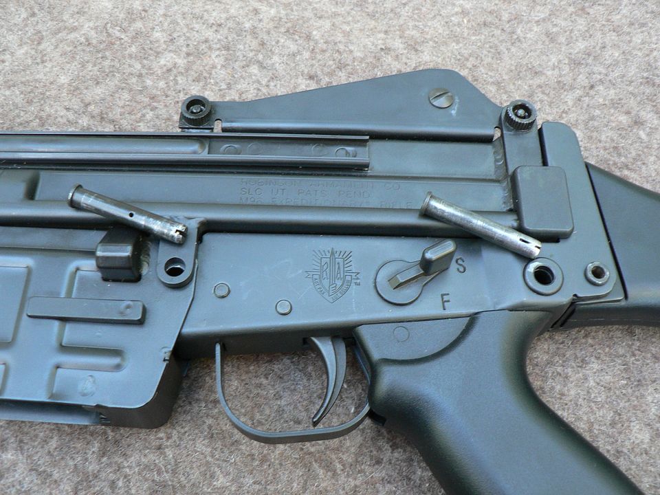
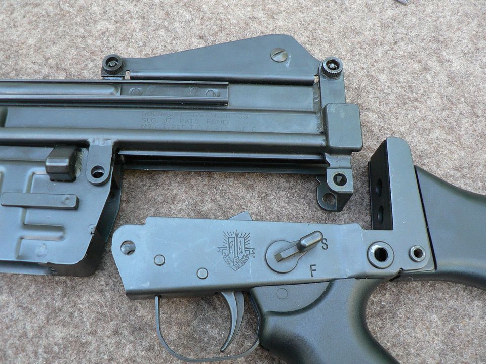
Nice Job ProbableColtAddict!  I have a green furniture Expeditionary a good friend gifted me 2-3 years ago.  He still has a black furniture Recon I believe.  I really wanted one in the late 90s due to the VN Navy Seal stories using the Stoner-63.  I zeroed mine and it lives in my safe now.  It is a very well built rifle with a true Milspec trigger, (awful just like the real thing).  Of course it is not a precision weapon, I am just spoiled from installing or improving my own AR triggers.
ETA:  I will take pictures and post them next time I open my safe.
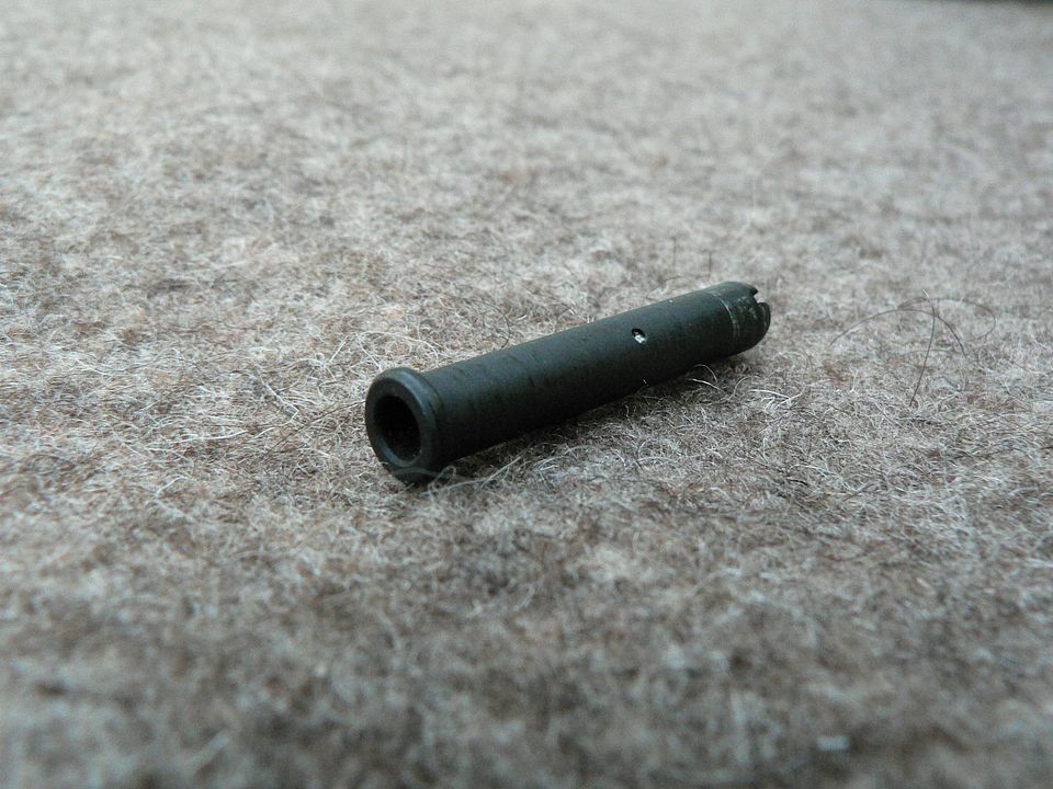
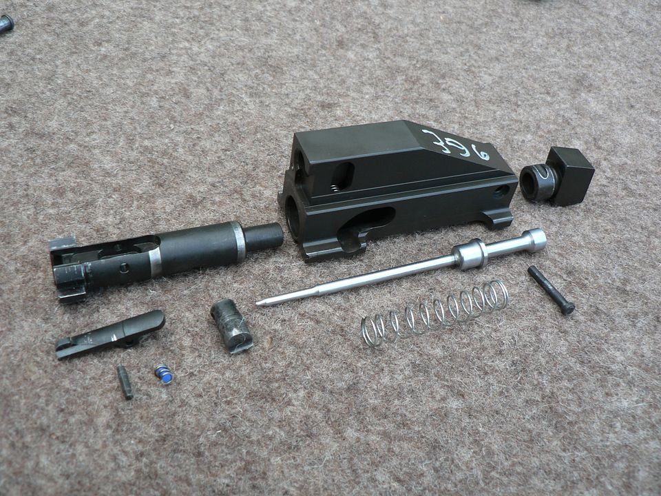
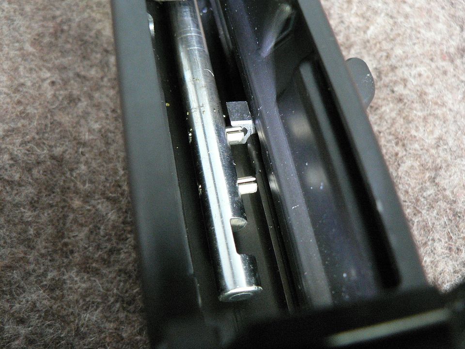
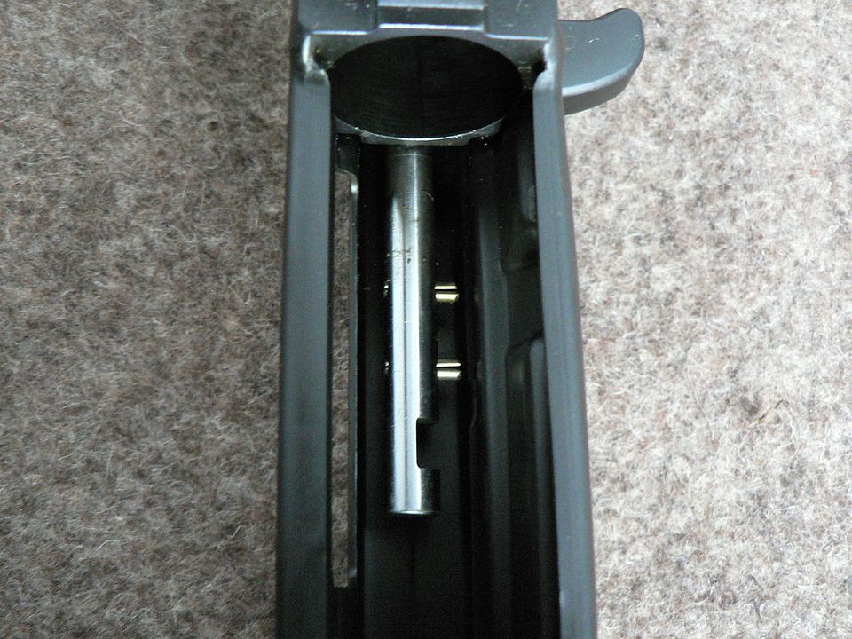
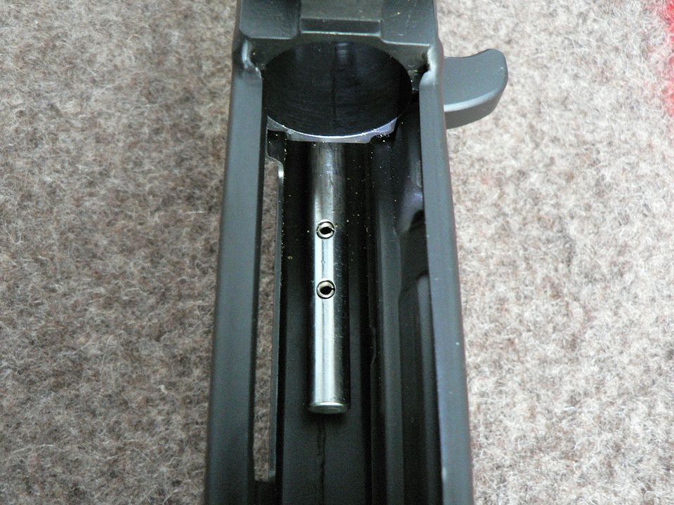
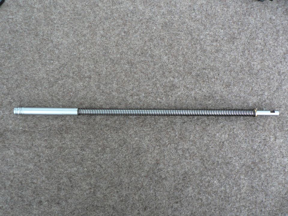
Link Posted: 7/24/2021 8:36:53 PM EDT
[#37]
After removal of the barrel and gas tube, we complete disassembly of the gas system by removing the gas piston/operating rod assembly.  But before we do that, I want to look at how the assembly interacts with the charging handle and explain why you must NEVER pull back on the charging handle and let it fly home without the rifle fully assembled.  
We start with a picture looking up into the bottom of the receiver after having removed the bolt assembly and barrel:

The silver bit is the rear of the operating rod (referred to as the op rod going forward) at rest.  However, this picture doesn't help us much in explaining anything.  All it's really showing is what you will see when you look up into the bottom of the receiver.

To see what's really going on here, we need to push the op rod to the rear a little bit.  We have done that in the picture below:

Let me explain what you are looking at.
The notch cut into the the op rod near its rear is what's grabbed by the lug on the disassembly button in the bolt carrier.  Pushing the button on the right side of the bolt carrier disengages the lug from this notch and decouples the carrier from the op rod.
Forward of this notch are two roll pins sticking out the side of the op rod.  The rearmost pin runs into the front face of the bolt carrier upon reassembly and prevents over insertion of the op rod into the bolt carrier.  The forward pin is used to charge the rifle.  In fact, it is shown in contact with a lug protruding out the back of the charging handle.  It is important to understand that this pin is in no way attached to the charging handle because the rifle has a nonreciprocating charging handle.  
Remember that the recoil spring is part of the gas piston/op rod assembly.  
Knowing these things, it should now be clear why you must never charge the rifle unless it is fully assembled.  When the rifle is assembled and the mechanism is allowed to run home, the inertia created by the drive spring is transferred into the relatively heavy steel barrel and trunnion with the bolt assembly acting as a sort of damper.  But without the barrel and bolt assembly in place, ALL of that inertia is transferred into that little roll pin when the mechanism comes to rest.  How many times to you think that can happen without the roll pin become mangled and shearing off?  This setup was later redesigned and the roll pins replaced with a lug welded to the op rod but the later manual still advised against charging the rifle unless the barrel is installed.  This setup is one of the weakest points of this design but it's really a nonissue if you have educated yourself about the rifle BEFORE mucking about with it.  Things like this are why I'm a big believer in reading the manual before picking up your firearm.  


ALrighy.  With that warning out of the way, I'll now explain how to remove the gas piston/op rod assembly. It's really simple.
First, push the gas piston to the rear until the forward roll pin on the op rod is disengaged from the protrusion on the charging handle.  The position show below is more than sufficient:


Next, rotate the assembly either clockwise or counterclockwise 90 degrees until the pins are pointing at the top of the receiver:


Ease the assembly forward until you no longer feel pressure from the drive spring and remove it from the front of the receiver:


Now that it's out, we'll look at it in some detail.
At the front of the assembly is the chromed gas piston:


It's held onto the op rod by a roll pin:

The piston could have been machined as part of the op rod I guess but I think part of the idea in doing it this way was to allow a bit of articulation to reduce stress on the assembly as it reciprocates.


A detail photo of the piston head:


The rear of the op rod showing the already talked about notch and roll pins:


The brass ring between the drive spring and the forward roll pin rests against the front of the trunnion when assembled.


In this picture, we see the op rod at the point of initial insertion into the bolt carrier:


And here, the op rod has been coupled with the bolt carrier, illustrating the the rear pin on the op rod resting against the front face of the bolt carrier:


Coupled op rod and bolt carrier as seen from the right side:


While looking at the various parts of the gas system employed on the M96, it may have reminded you of something you've seen before.  If so, you memory has served you well!  In fact, it's derived from that used on both the Beretta AR70 and SIG 55X series of rifles and both of those designs are based on an earlier system designed jointly by Beretta and SIG before going their own ways....but that's beyond the scope of this article.  
Still, just for the fun of it, here is the M96 compared to a SIG 551:

It should be pointed out that we are considering only the gas system here and not the locking system.  The M96, as we have seen, has a locking system based on the AR-180 while the 551 is based on the AK-47
On the 551, the op rod is connected to the bolt carrier by way of the reciprocating charging handle but the two systems are very similar otherwise.  Both have a removeable gas full length gas tube, both employ a long stroke system where the op rod can be easily disassembled from the bolt group and both have their drive spring mounted around the op rod instead of the more traditional placement behind the bolt group.  Stuff like this absolutely fascinates me and it's a large reason why I collect firearms.


SO that's it for this installment.  In the next, we'll take a detailed look at the receiver.  Later, I'll go over some cleaning suggestions and we'll finish up by comparing the M96 to a Stoner 63.  Until then, enjoy the summer.  It's been a hot one here, just the way I like it!
Link Posted: 8/3/2021 12:05:45 AM EDT
[#38]
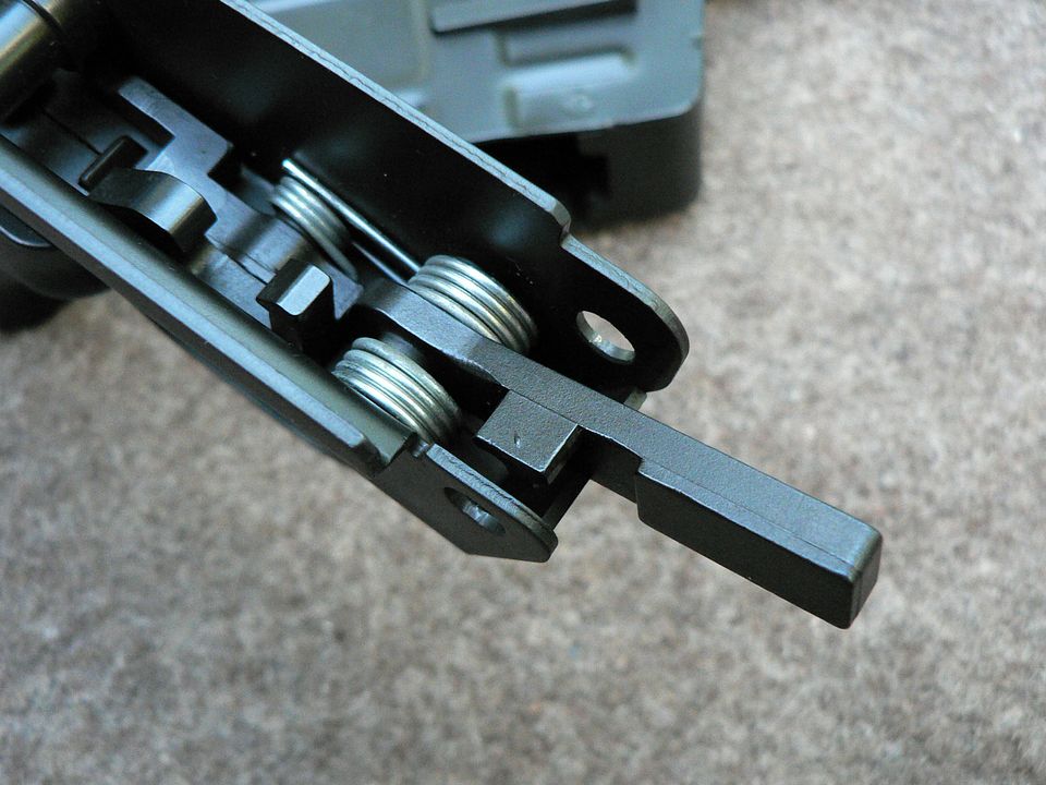
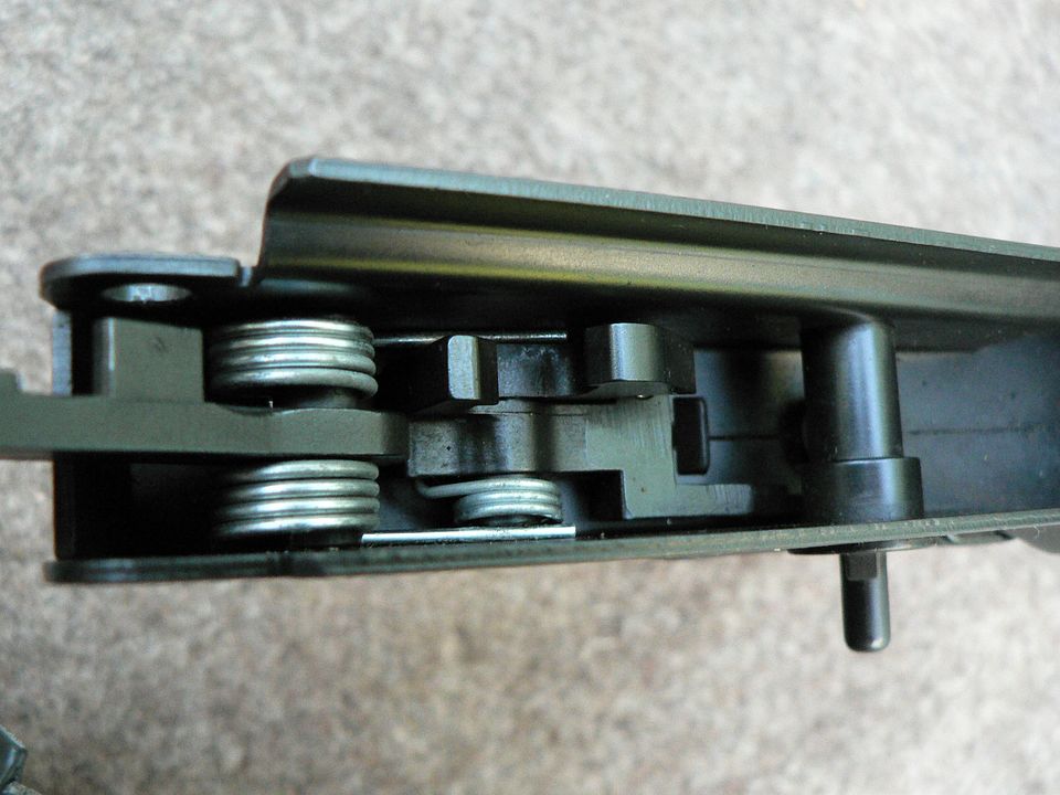
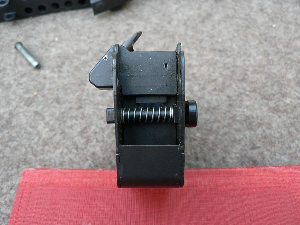
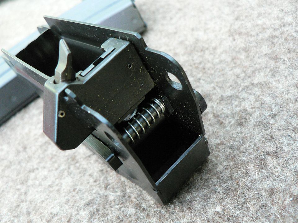
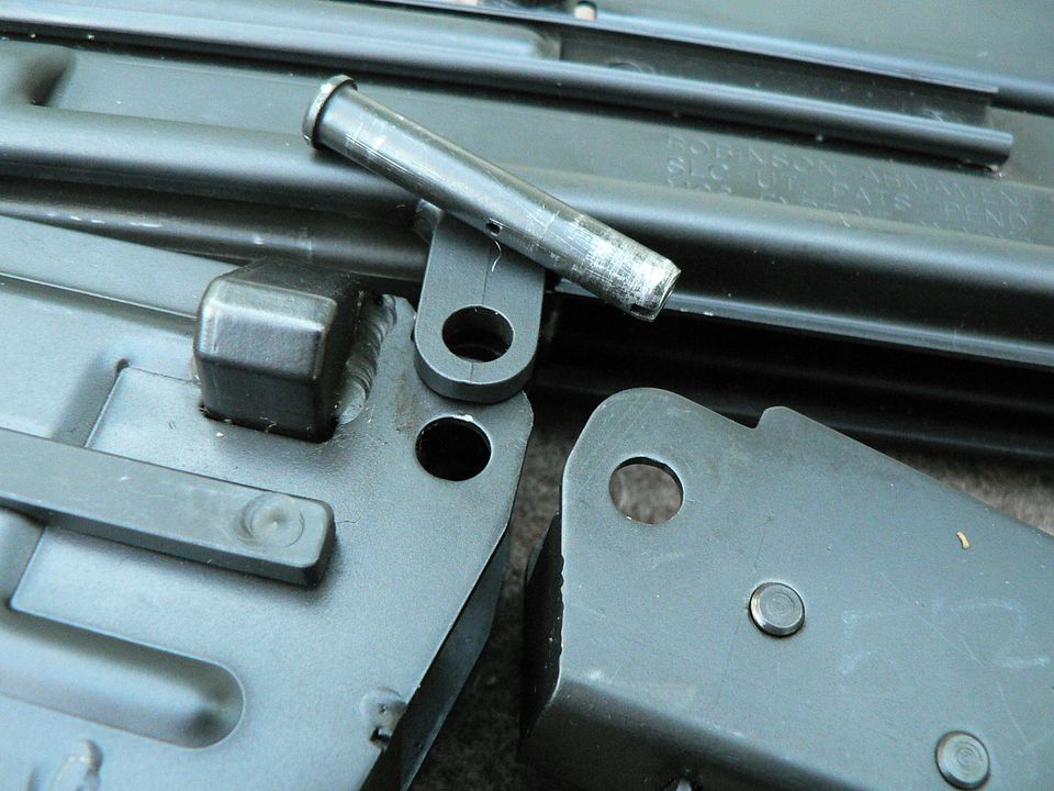
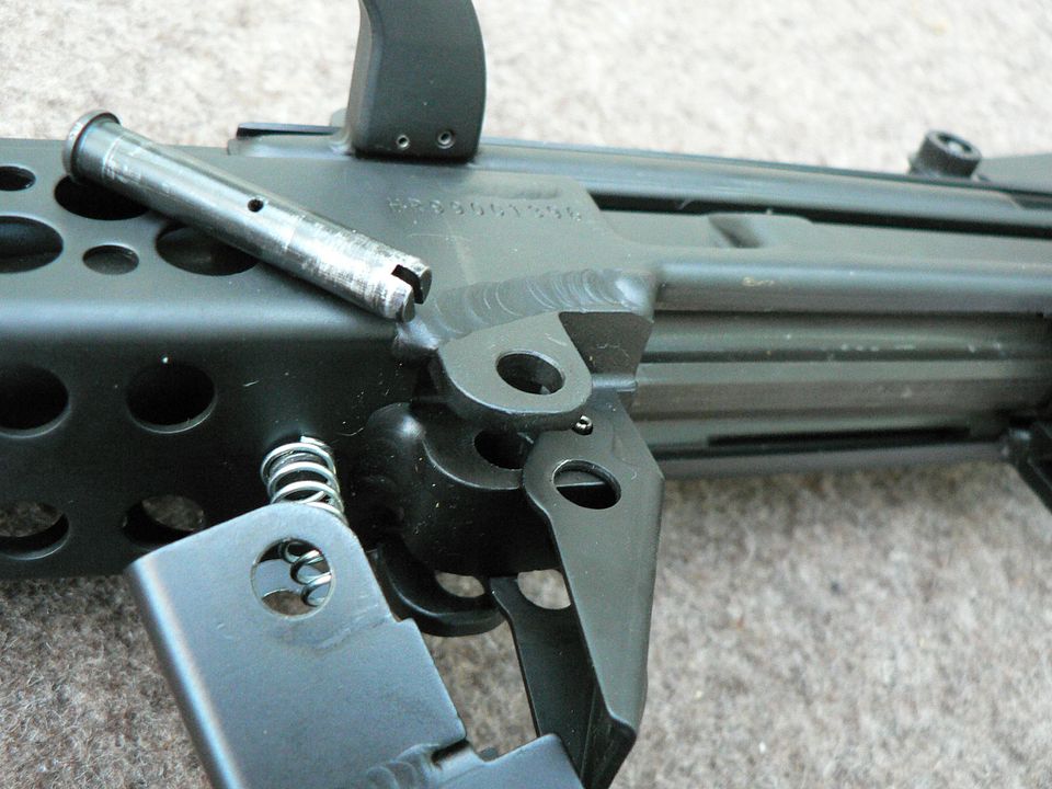
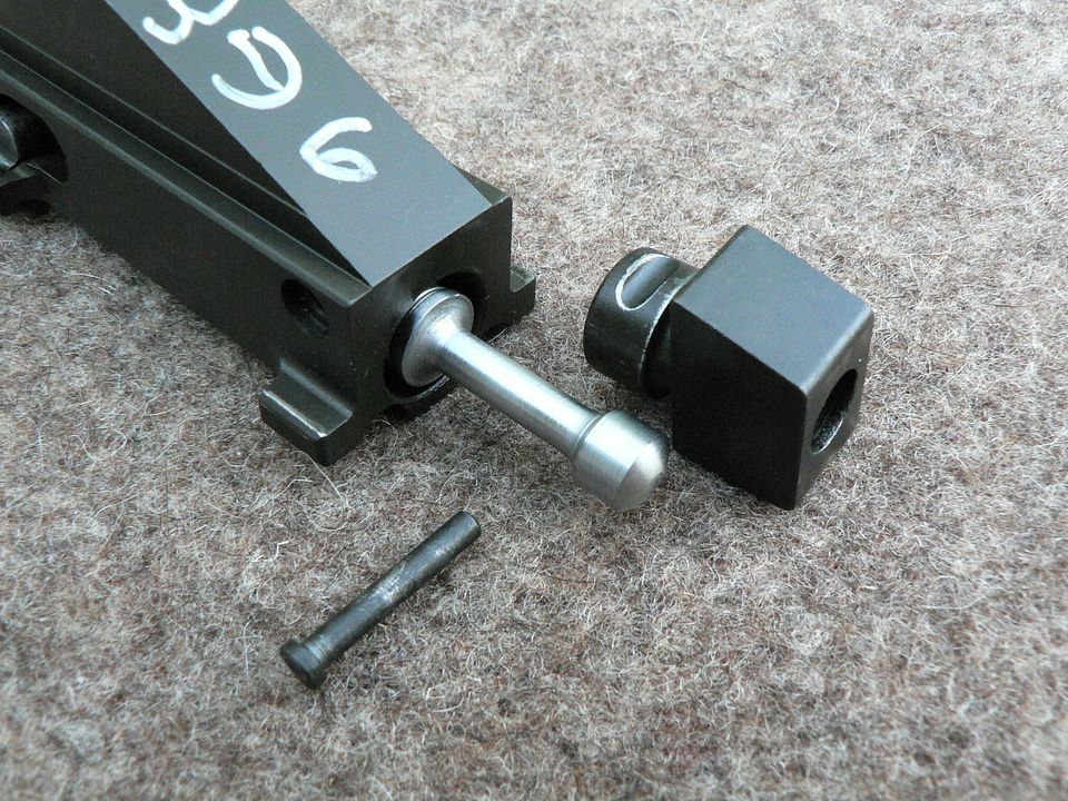
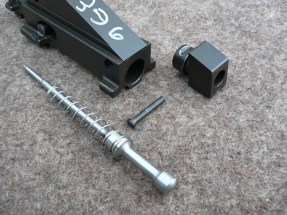
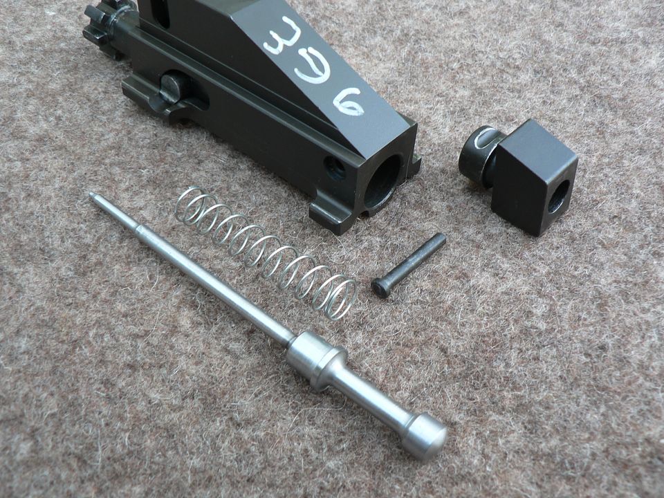
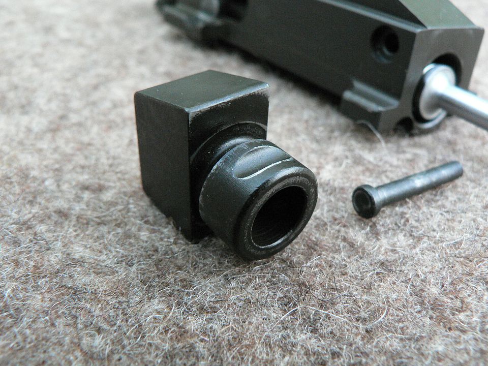
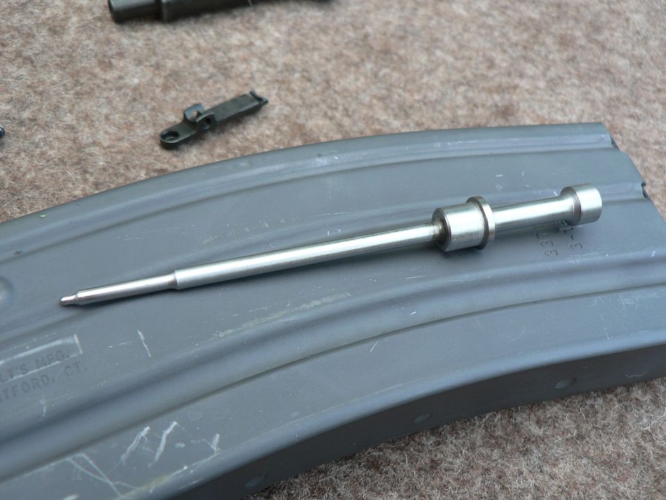
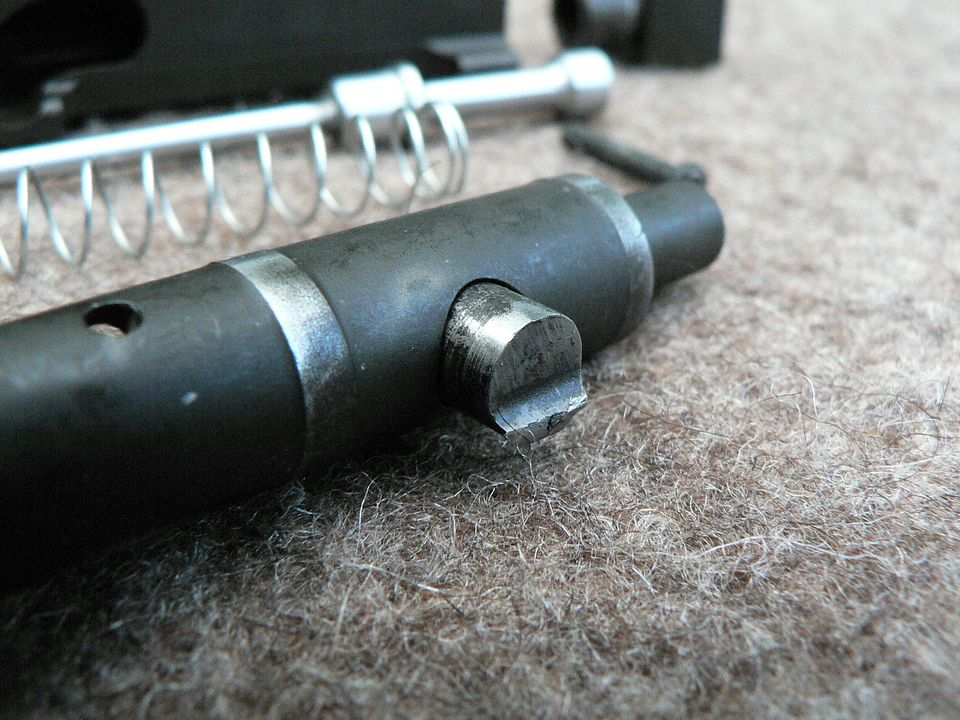
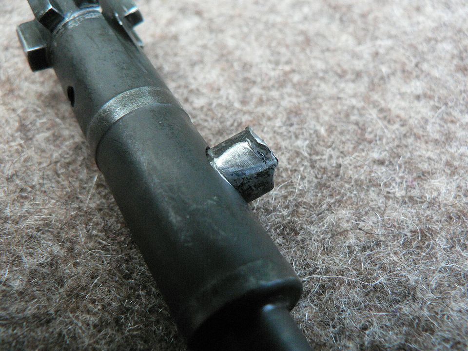
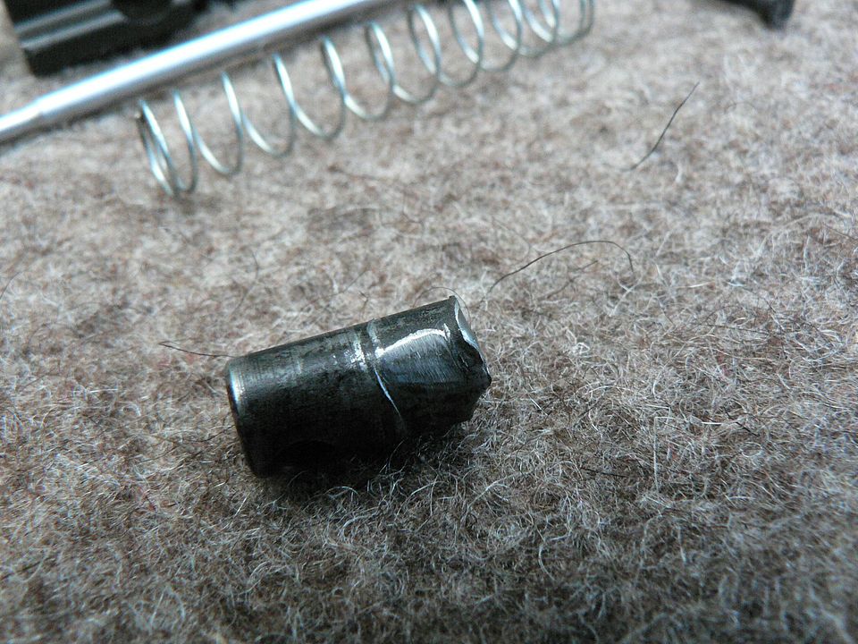
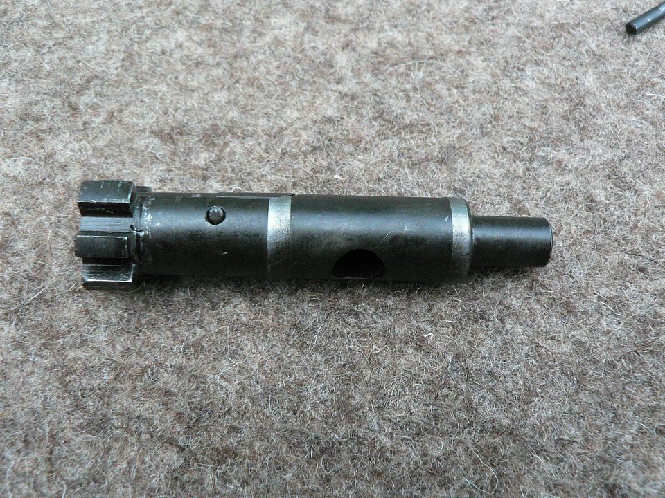
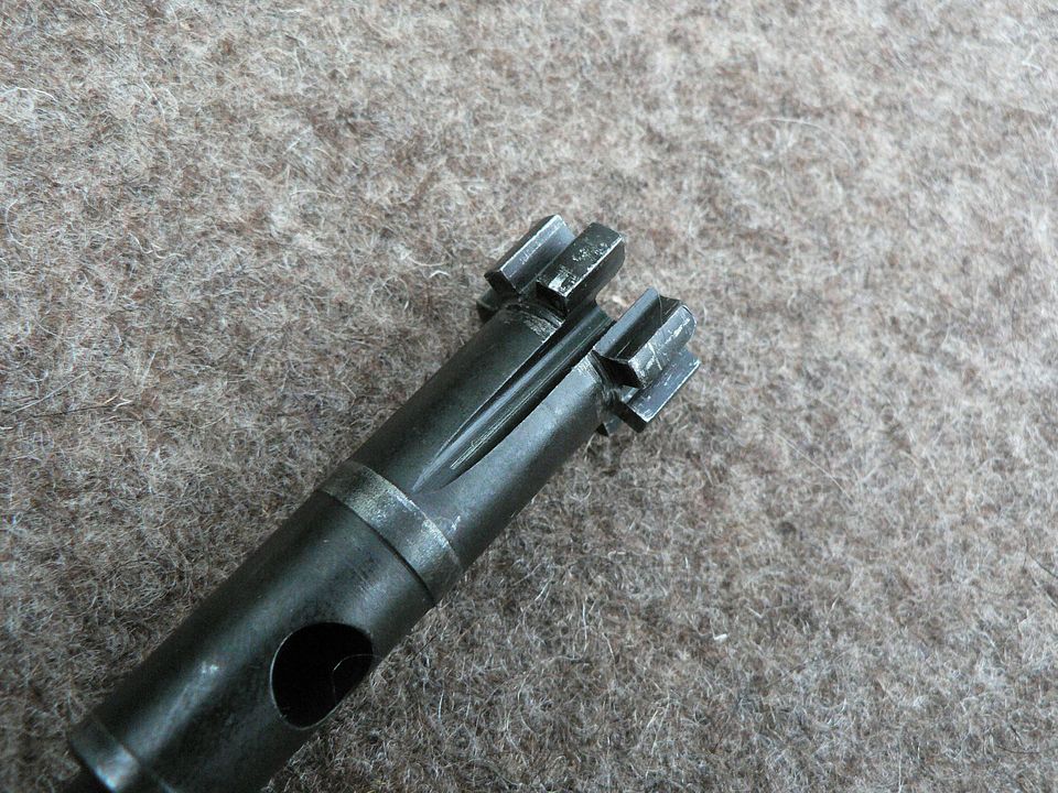
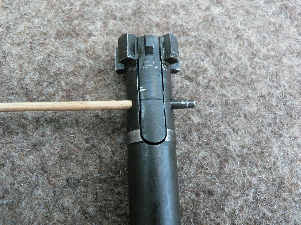
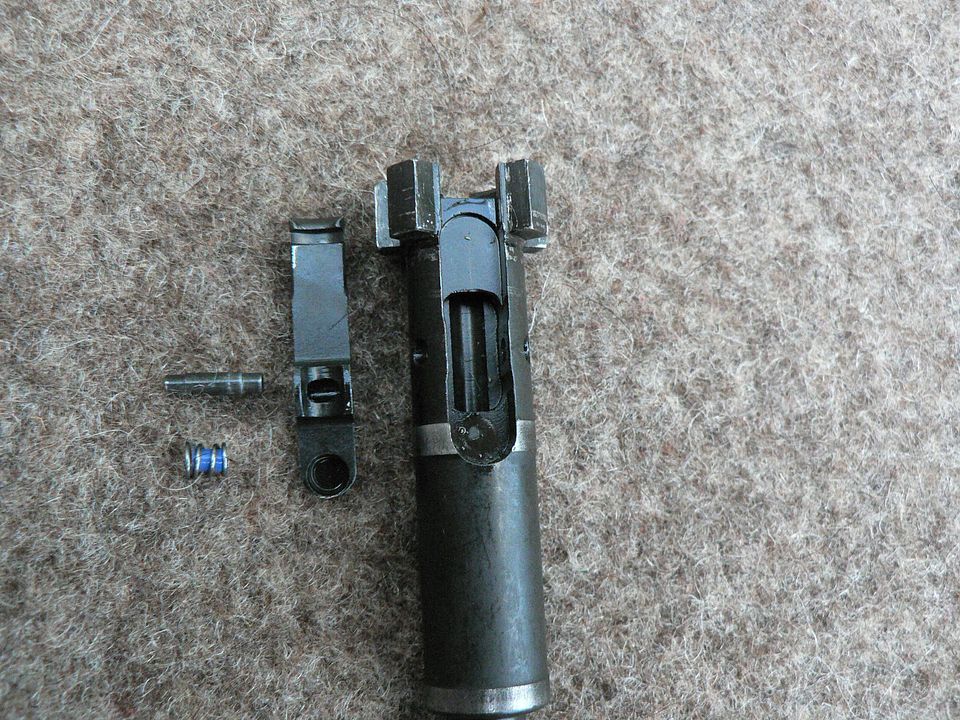
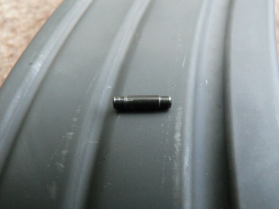
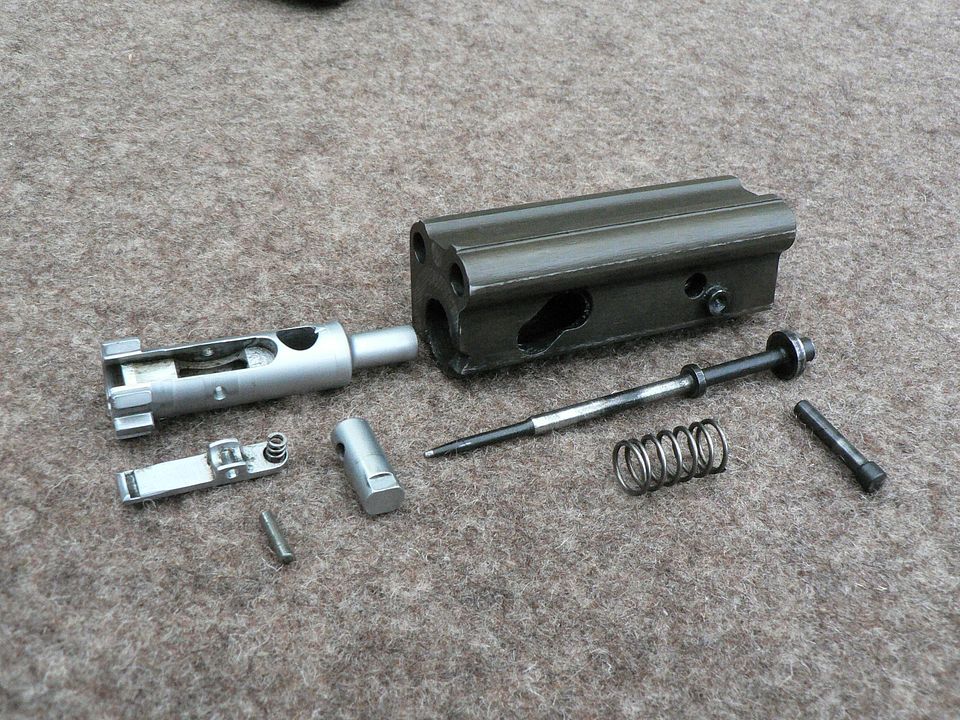
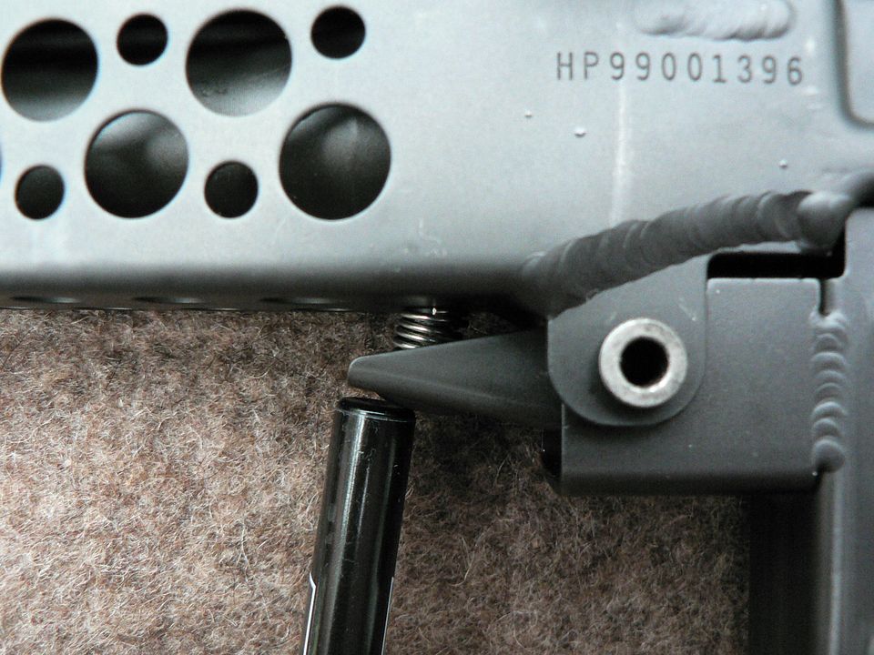
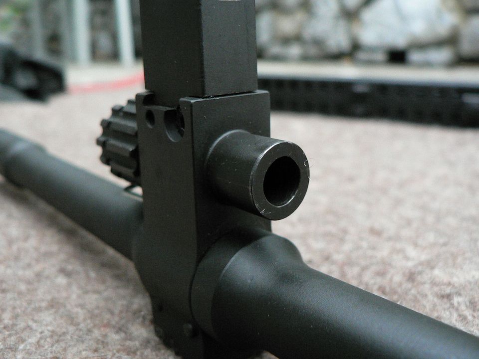
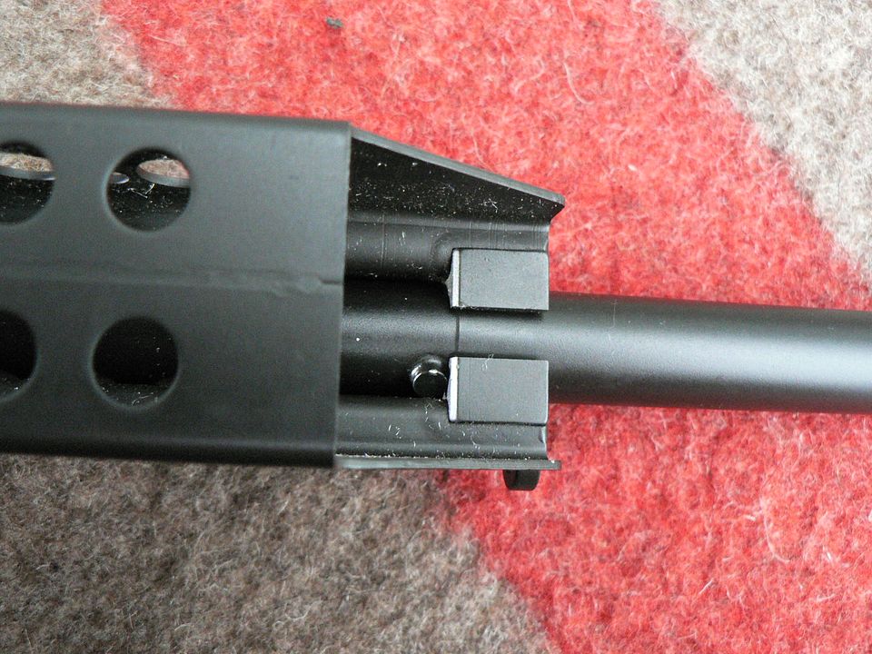
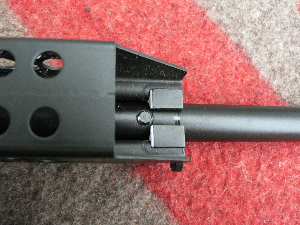
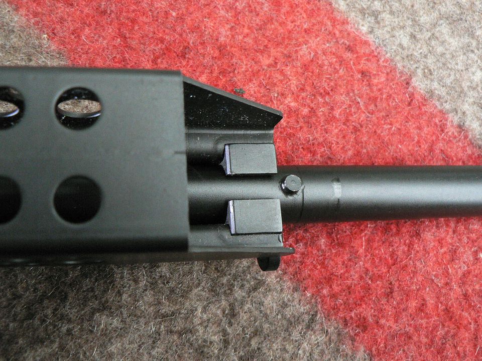
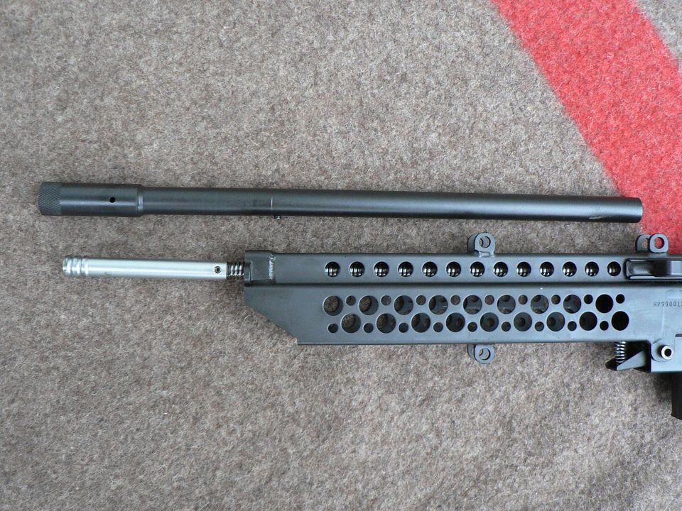
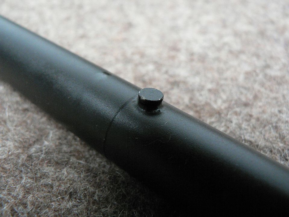
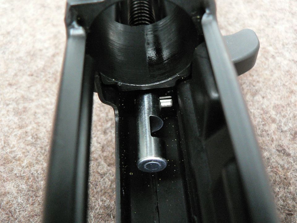
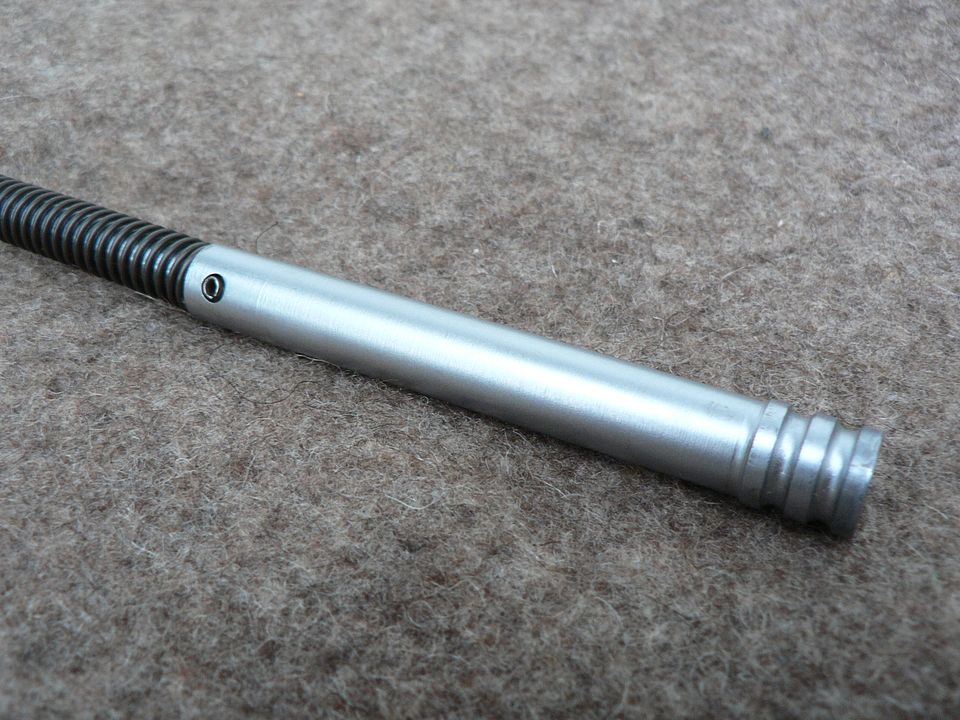
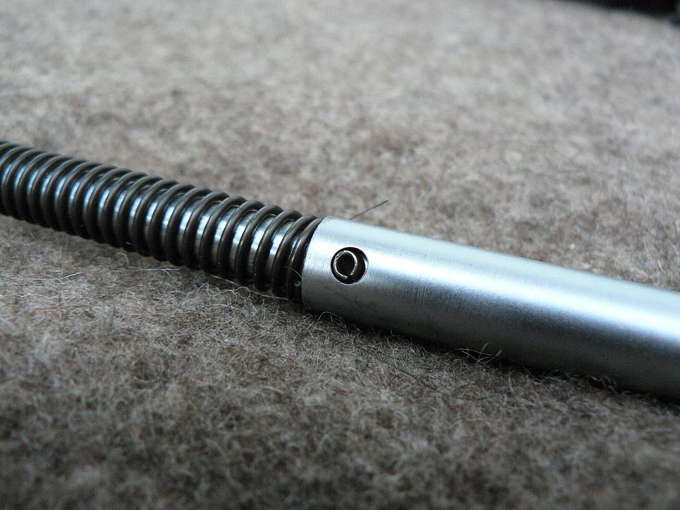
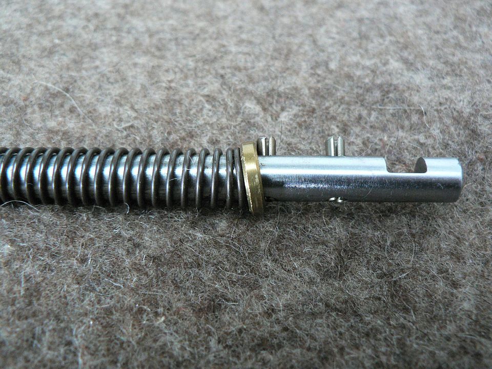
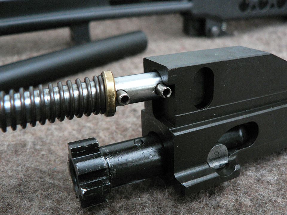
I'll add in, that's the first gas piston design that didn't last long. The problem with it was the roll pin would walk out and gouge the inside of the gas tube. RA came out with a newer design pretty quick where the piston screwed onto the op-rod. They sold that as a upgrade for if I remember correct $48.00.


Owner of a M96 top feed and M96 Recon. Both were bought as early rifles in 1998(by me) and upgraded with kits RA sold.
Page AR-15 » AR-15 / M-16 Retro Forum
AR Sponsor: bravocompany
Close Join Our Mail List to Stay Up To Date! Win a FREE Membership!

Sign up for the ARFCOM weekly newsletter and be entered to win a free ARFCOM membership. One new winner* is announced every week!

You will receive an email every Friday morning featuring the latest chatter from the hottest topics, breaking news surrounding legislation, as well as exclusive deals only available to ARFCOM email subscribers.


By signing up you agree to our User Agreement. *Must have a registered ARFCOM account to win.
Top Top