


Posted: 4/24/2016 5:55:53 PM EDT
| Is it possible for a power to enter recessed lights, then go to a switch? I have wired them all with 14-2 and the switch is at the end of the run. The challenge I believe is that recessed lights should be connected in parallel rather than series when wiring multiple lights and typically power enters the switch before going to fixtures. I'm sure this would be possible with 14-3, but like I said, the entire run has been done in 14-2. Thanks! |

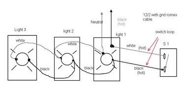
| Power goes to the fixture, but the hot wire (black) is first wired from there to the switch. Wire both black and white wire to the switch. Tape the neutral wire black to indicate it's a switch leg then, back at the fixture, your taped white wire is now your hot and is connected to the first fixture. All fixtures will use a hot and neutral wire (of corse ground) like you mentioned in parallel. |
| Well, I Think I've royally screwed up. I'll post a diagram in a bit. Basically, I was trying to do power-fixture(x7 lights)-switch-switch. The problem is, I only ran 14/2 to all the lights and to the first switch, then 14/3 between the switches. I'm doing a horrible job explaining, so I'll post a diagram. Either way, I think I'm hosed. |
|
Quoted:
Well, I Think I've royally screwed up. I'll post a diagram in a bit. Basically, I was trying to do power-fixture(x10 lights)-switch-switch. The problem is, I only ran 14/2 to all the lights and to the first switch, then 14/3 between the switches. I'm doing a horrible job explaining, so I'll post a diagram. Either way, I think I'm hosed. You mean you're trying to run a 3-way switch (2 switches control the lights)? Yeah, I'm pretty sure you need a traveler to the 2nd switch... can you pull 14/3 to the 2nd switch? |
|
Sorry, I misled in the OP. I've got a bunch of pot lights that have power coming in on light #1, then the switch is connected to light #7, which then runs to the end of the run which is the final 3 way switch. All wiring is 14/2 except for the wire between the two 3 way switches, which is 14/3. The outside 3 way switch is the "end of the run." Here's a crude drawing. The black/HOT that comes from the panel never connects directly to a light, it's just spliced together in the junction box.
Like I said, I was seriously challenged in this design by my idiocy. Any way to salvage this? The only solution I see is to feed power into the OUTSIDE 3 Way Switch instead of trying to feed power at Light #1, then rewire each pot light so they are in parallel instead of series. 
|
|
You're doing it wrong, OP. The power goes through the switches first. Then the switched wires feed the lights. http://www.buildmyowncabin.com/electrical/wiring-diagrams-3way-7.html |
|
Quoted:
You're doing it wrong, OP. The power goes through the switches first. Then the switched wires feed the lights. http://www.buildmyowncabin.com/electrical/wiring-diagrams-3way-7.html Switch loops are as common as dirt. You do need three conductor cable now so that you can provide a neutral at the switch. Many new switches have electronics (timers, motion snsors, etc.) and require a neutral in the switch box to operate. |
|
Quoted:
Switch loops are as common as dirt. You do need three conductor cable now so that you can provide a neutral at the switch. Many new switches have electronics (timers, motion snsors, etc.) and require a neutral in the switch box to operate. Quoted:
Quoted:
You're doing it wrong, OP. The power goes through the switches first. Then the switched wires feed the lights. http://www.buildmyowncabin.com/electrical/wiring-diagrams-3way-7.html Switch loops are as common as dirt. You do need three conductor cable now so that you can provide a neutral at the switch. Many new switches have electronics (timers, motion snsors, etc.) and require a neutral in the switch box to operate. In a switch loop, power goes through the switch first. And then the switched wires feed the lights. Which is exactly what I said. If you look at the OP's diagram, he wants to hook the lights up to the incoming unswitched hot wire first, and then run it through the switches. Obviously that won't work. Instead of just cookbooking through diagrams I was trying to explain to the OP where he was making an error. Unfortunately many so-called electricians aren't capable of doing anything except following a few simple wiring diagrams and don't really understand where the current is flowing. |
|
Quoted:
You're doing it wrong, OP. The power goes through the switches first. Then the switched wires feed the lights. http://www.buildmyowncabin.com/electrical/wiring-diagrams-3way-7.html See, I thought I had done that. By taking the unswitched hot power from the panel and running it straight to the switch (through the trail of lights). Just to be clear, the HOT/Black cable from the panel never actually gets spliced to a light, it's just wire nutted to the other black wire in the fixture junction box. Then once the power leaves the switch via a white marked black cable, it connects in series to the lights on the return path. I was basically making the black wire just a traveler. Or at least that's what I thought I was doing. |
|
Quoted:
If you look at the OP's diagram, he wants to hook the lights up to the incoming unswitched hot wire first, and then run it through the switches. Obviously that won't work. That's where my diagram skills are lacking.  The unswitched hot is going to the switches first, just by using the black wire of the 14/2 that is running with the lights. The unswitched hot is going to the switches first, just by using the black wire of the 14/2 that is running with the lights.
And thank you to all for the help, I do appreciate it. |
|
Quoted:
Sorry, I misled in the OP. I've got a bunch of pot lights that have power coming in on light #1, then the switch is connected to light #7, which then runs to the end of the run which is the final 3 way switch. All wiring is 14/2 except for the wire between the two 3 way switches, which is 14/3. The outside 3 way switch is the "end of the run." Here's a crude drawing. The black/HOT that comes from the panel never connects directly to a light, it's just spliced together in the junction box. Like I said, I was seriously challenged in this design by my idiocy. Any way to salvage this? The only solution I see is to feed power into the OUTSIDE 3 Way Switch instead of trying to feed power at Light #1, then rewire each pot light so they are in parallel instead of series. https://farm2.staticflickr.com/1464/26611593276_53790245da_z.jpg Well, it's not the end of the world... The lights will light ---but dimly... Because they're all wired in SERIES... 
|
|
Quoted:
In a switch loop, power goes through the switch first. And then the switched wires feed the lights. Which is exactly what I said. If you look at the OP's diagram, he wants to hook the lights up to the incoming unswitched hot wire first, and then run it through the switches. Obviously that won't work. Instead of just cookbooking through diagrams I was trying to explain to the OP where he was making an error. Unfortunately many so-called electricians aren't capable of doing anything except following a few simple wiring diagrams and don't really understand where the current is flowing. Quoted:
Quoted:
Quoted:
You're doing it wrong, OP. The power goes through the switches first. Then the switched wires feed the lights. http://www.buildmyowncabin.com/electrical/wiring-diagrams-3way-7.html Switch loops are as common as dirt. You do need three conductor cable now so that you can provide a neutral at the switch. Many new switches have electronics (timers, motion snsors, etc.) and require a neutral in the switch box to operate. In a switch loop, power goes through the switch first. And then the switched wires feed the lights. Which is exactly what I said. If you look at the OP's diagram, he wants to hook the lights up to the incoming unswitched hot wire first, and then run it through the switches. Obviously that won't work. Instead of just cookbooking through diagrams I was trying to explain to the OP where he was making an error. Unfortunately many so-called electricians aren't capable of doing anything except following a few simple wiring diagrams and don't really understand where the current is flowing. In a switch loop power goes through the light first and then is routed to the switch and back to the light. It is exactly the opposite of what you are saying. That is the loop to the switch. The correct method is to use the the white wire to the switch to feed power. The wire does not need to be marked at tejh light since it is clear it is being fed by a hot line. It is marked at the switch as a confirmation it is NOT a neutral under newer codes editions. The black is then use to carry the power back to the light. It makes it self explanatory at each box when you see a black feeding the light and the fastened to the black to feed the switch. When wired in this way older code revisions did not even require marking the white wire at the switch. |
|
Quoted:
Well, it's not the end of the world... The lights will light ---but dimly... Because they're all wired in SERIES...
Quoted:
Quoted:
Sorry, I misled in the OP. I've got a bunch of pot lights that have power coming in on light #1, then the switch is connected to light #7, which then runs to the end of the run which is the final 3 way switch. All wiring is 14/2 except for the wire between the two 3 way switches, which is 14/3. The outside 3 way switch is the "end of the run." Here's a crude drawing. The black/HOT that comes from the panel never connects directly to a light, it's just spliced together in the junction box. Like I said, I was seriously challenged in this design by my idiocy. Any way to salvage this? The only solution I see is to feed power into the OUTSIDE 3 Way Switch instead of trying to feed power at Light #1, then rewire each pot light so they are in parallel instead of series. https://farm2.staticflickr.com/1464/26611593276_53790245da_z.jpg Well, it's not the end of the world... The lights will light ---but dimly... Because they're all wired in SERIES...
He could wire them in parallel the way he has it, and he could even use the switch to "turn them off", but then he would have to flip the switch back and go reset the breaker to get them to come back on again... |
|
Quoted:
He could wire them in parallel the way he has it, and he could even use the switch to "turn them off", but then he would have to flip the switch back and go reset the breaker to get them to come back on again... Quoted:
Quoted:
Quoted:
Sorry, I misled in the OP. I've got a bunch of pot lights that have power coming in on light #1, then the switch is connected to light #7, which then runs to the end of the run which is the final 3 way switch. All wiring is 14/2 except for the wire between the two 3 way switches, which is 14/3. The outside 3 way switch is the "end of the run." Here's a crude drawing. The black/HOT that comes from the panel never connects directly to a light, it's just spliced together in the junction box. Like I said, I was seriously challenged in this design by my idiocy. Any way to salvage this? The only solution I see is to feed power into the OUTSIDE 3 Way Switch instead of trying to feed power at Light #1, then rewire each pot light so they are in parallel instead of series. https://farm2.staticflickr.com/1464/26611593276_53790245da_z.jpg Well, it's not the end of the world... The lights will light ---but dimly... Because they're all wired in SERIES...
He could wire them in parallel the way he has it, and he could even use the switch to "turn them off", but then he would have to flip the switch back and go reset the breaker to get them to come back on again... That wouldn't be any fun... 
|
|
Quoted:
In a switch loop power goes through the light first and then is routed to the switch and back to the light. It is exactly the opposite of what you are saying. That is the loop to the switch. Quoted:
Quoted:
Quoted:
Quoted:
You're doing it wrong, OP. The power goes through the switches first. Then the switched wires feed the lights. http://www.buildmyowncabin.com/electrical/wiring-diagrams-3way-7.html Switch loops are as common as dirt. You do need three conductor cable now so that you can provide a neutral at the switch. Many new switches have electronics (timers, motion snsors, etc.) and require a neutral in the switch box to operate. In a switch loop, power goes through the switch first. And then the switched wires feed the lights. Which is exactly what I said. If you look at the OP's diagram, he wants to hook the lights up to the incoming unswitched hot wire first, and then run it through the switches. Obviously that won't work. Instead of just cookbooking through diagrams I was trying to explain to the OP where he was making an error. Unfortunately many so-called electricians aren't capable of doing anything except following a few simple wiring diagrams and don't really understand where the current is flowing. In a switch loop power goes through the light first and then is routed to the switch and back to the light. It is exactly the opposite of what you are saying. That is the loop to the switch. Really. According to your own diagram the power is first switched and then goes to the light. The black wire is the hot that supplies the switch, and the black/white traveler is the switched current that supplies the black wire on the light fixture. The white wires are the neutrals. |
|
Quoted:
Really. According to your own diagram the power is first switched and then goes to the light. The black wire is the hot that supplies the switch, and the black/white traveler is the switched current that supplies the black wire on the light fixture. The white wires are the neutrals. I don't see a diagram that brickeye posted? Anyways, I think OP was trying to do something similar to this 3-way wiring diagram, but didn't quite do it right. |
|
Quoted:
That's where my diagram skills are lacking. The unswitched hot is going to the switches first, just by using the black wire of the 14/2 that is running with the lights.
And thank you to all for the help, I do appreciate it. Quoted:
Quoted:
If you look at the OP's diagram, he wants to hook the lights up to the incoming unswitched hot wire first, and then run it through the switches. Obviously that won't work. That's where my diagram skills are lacking. The unswitched hot is going to the switches first, just by using the black wire of the 14/2 that is running with the lights.
And thank you to all for the help, I do appreciate it. Did you figure out what needs done? |
|
Quoted:
That wouldn't be any fun...
Quoted:
Quoted:
He could wire them in parallel the way he has it, and he could even use the switch to "turn them off", but then he would have to flip the switch back and go reset the breaker to get them to come back on again... That wouldn't be any fun...
Depends on your idea of fun... if intentionally creating a dead-short an inch away from your hand with a light switch sounds like fun to you then it could be fun!!!! 
Quoted:
Quoted:
Really. According to your own diagram the power is first switched and then goes to the light. The black wire is the hot that supplies the switch, and the black/white traveler is the switched current that supplies the black wire on the light fixture. The white wires are the neutrals. I don't see a diagram that brickeye posted? Anyways, I think OP was trying to do something similar to this 3-way wiring diagram, but didn't quite do it right. He did it "right" but didn't realize that wiring cannot be done for multiple lights in parallel as shown (with 14/2). He needs 14/3 between each of the lights to make that happen. |
|
Quoted:
Depends on your idea of fun... if intentionally creating a dead-short an inch away from your hand with a light switch sounds like fun to you then it could be fun!!!!
He did it "right" but didn't realize that wiring cannot be done for multiple lights in parallel as shown (with 14/2). He needs 14/3 between each of the lights to make that happen. Quoted:
Quoted:
Quoted:
He could wire them in parallel the way he has it, and he could even use the switch to "turn them off", but then he would have to flip the switch back and go reset the breaker to get them to come back on again... That wouldn't be any fun...
Depends on your idea of fun... if intentionally creating a dead-short an inch away from your hand with a light switch sounds like fun to you then it could be fun!!!!
Quoted:
Quoted:
Really. According to your own diagram the power is first switched and then goes to the light. The black wire is the hot that supplies the switch, and the black/white traveler is the switched current that supplies the black wire on the light fixture. The white wires are the neutrals. I don't see a diagram that brickeye posted? Anyways, I think OP was trying to do something similar to this 3-way wiring diagram, but didn't quite do it right. He did it "right" but didn't realize that wiring cannot be done for multiple lights in parallel as shown (with 14/2). He needs 14/3 between each of the lights to make that happen. He only needs 14/3 where he hooks up his 3 way switches to power and the light 'string'... The light 'string' can be wired with 14/2 |
Well, I finally ended up running power to the 3 way switch at the outside door. (See drawing above). Basically, I took the HOT from a circuit that was feeding 3 outlets and pig tailed it to the 3 way switch. Once I did that and then wired the lights in parallel it worked perfectly. Thanks for the help guys. For some reason, I just thought these lights could work in series and without a neutral. /smh

|
|
Quoted:
Well, I finally ended up running power to the 3 way switch at the outside door. (See drawing above). Basically, I took the HOT from a circuit that was feeding 3 outlets and pig tailed it to the 3 way switch. Once I did that and then wired the lights in parallel it worked perfectly. Thanks for the help guys. For some reason, I just thought these lights could work in series and without a neutral. /smh https://farm2.staticflickr.com/1459/26081880673_9c9e4ffbb9_z.jpg Good, are those LEDS? |
| As of right now, they are my father in law's 65W regular indoor floods. He gave me those when he replaced his lights with LED's. I will keep these for now, then once I get the dimmer switch installed, will have to switch to LED's or something else as it can only handle 600W standard light or 300W LED/CFL. With 11 lights, 65W is clearly too much for the dimmer, plus I do want to reduce wattage since I ended up sharing this circuit with 3 outlets. |
|
Quoted:
He only needs 14/3 where he hooks up his 3 way switches to power and the light 'string'... The light 'string' can be wired with 14/2 That's correct only if he runs power to the switch first. If he wants power running through the lights first (like that diagram shows) then he needed 14/3 in order to still have an extra wire to run the lights in parallel. |
|
Quoted:
That's correct only if he runs power to the switch first. If he wants power running through the lights first (like that diagram shows) then he needed 14/3 in order to still have an extra wire to run the lights in parallel. Quoted:
Quoted:
He only needs 14/3 where he hooks up his 3 way switches to power and the light 'string'... The light 'string' can be wired with 14/2 That's correct only if he runs power to the switch first. If he wants power running through the lights first (like that diagram shows) then he needed 14/3 in order to still have an extra wire to run the lights in parallel. Absolutely correct. You need an extra wire to run the switched hot to the lights. The switch loop is often taken off the closest light to the switch (wire costs money). Now you need to get it to all the lights in the row. |