


ITT We post pics and talk about our ham projects, big or small. (Page 19 of 19)

|
Hopefully this is allowed as this is ham radio adjacent Having a consumer audio background and my interest in ham radio has somehow led me down the vintage radio rabbit hole. I’ve gone a bit nuts the last few months picking up a few stereo receivers locally on Facebook marketplace and a few more on shopgoodwill.com. I’ve been learning how to restore these guys, working on my troubleshooting and soldering skills. More importantly, if drastically improved my workbench situation adding a cheap oscilloscope and signal generator. Next I need to figure out what equipment I need to align the receivers in these guys which should directly tie back to amateur radio. Here’s a few pics. Maybe I’ll go start a thread in GD. Attached File Attached File Attached File Attached File Attached File Attached File Attached File Attached File |

|
Swept signal generator for front end alignment, fixed frequency generator that does FM Broadcast frequencies along with the commonly used IFs. The latter should be capable of WFM modulation. AF test generator of very low distortion along with a THD meter. Decent DMM and a 100+ MHz B/W scope. Noninductive dummy loads of 4 and 8 ohms. Frequency counter that's good to at least 200MHz and accompanying probes. That's what I usually tackle stereo gear with. |
|
New bench and operating desk project: Put the last shelf section in place last week and began putting power, ground, network and signal cable conduits in place. Installed 280 inches of 2x2 and 138 inches of 1.5x1 cable raceways last night. Another 60 inches of the latter on order. Then measured the runs to the secondary switch, primary to secondary KVM and ordered fiber, CAT6a to connect these up plus the cables required to connect the first shack PC to its switch and to the KVM. Only 14 more to build and cable. 
|

|
Originally Posted By tyrex13: Hopefully this is allowed as this is ham radio adjacent Having a consumer audio background and my interest in ham radio has somehow led me down the vintage radio rabbit hole. I’ve gone a bit nuts the last few months picking up a few stereo receivers locally on Facebook marketplace and a few more on shopgoodwill.com. I’ve been learning how to restore these guys, working on my troubleshooting and soldering skills. More importantly, if drastically improved my workbench situation adding a cheap oscilloscope and signal generator. Next I need to figure out what equipment I need to align the receivers in these guys which should directly tie back to amateur radio. Here’s a few pics. Maybe I’ll go start a thread in GD. https://www.ar15.com/media/mediaFiles/83116/IMG_5444_jpeg-3704492.JPG https://www.ar15.com/media/mediaFiles/83116/IMG_5441_jpeg-3704493.JPG https://www.ar15.com/media/mediaFiles/83116/IMG_5439_jpeg-3704494.JPG https://www.ar15.com/media/mediaFiles/83116/IMG_5397_jpeg-3704496.JPG https://www.ar15.com/media/mediaFiles/83116/IMG_5358_jpeg-3704497.JPG https://www.ar15.com/media/mediaFiles/83116/IMG_5446_jpeg-3704499.JPG https://www.ar15.com/media/mediaFiles/83116/IMG_5348_jpeg-3704500.JPG https://www.ar15.com/media/mediaFiles/83116/IMG_5259_jpeg-3704501.JPG I used to have a Sansui 9090. Loved it! |
Don't confuse where I live with where I'm from.
|
Originally Posted By tyrex13: It's a really cool piece of equipment. Don't look at what they're selling for now! Mine went belly up a long time ago, so I am not too concerned about what they are worth now. It was my stereo amp for the period of my life where I spent the most time listening to music, though. Many fond memories. I taped a lot of live concert broadcasts off of the FM tuner. |
Don't confuse where I live with where I'm from.
|
Originally Posted By AnalogKid: Swept signal generator for front end alignment, fixed frequency generator that does FM Broadcast frequencies along with the commonly used IFs. The latter should be capable of WFM modulation. AF test generator of very low distortion along with a THD meter. Decent DMM and a 100+ MHz B/W scope. Noninductive dummy loads of 4 and 8 ohms. Frequency counter that's good to at least 200MHz and accompanying probes. That's what I usually tackle stereo gear with. I have a scope, DMM and dummy load, but the rest of that still looks like a couple grand… |
|
Originally Posted By tyrex13: I have a scope, DMM and dummy load, but the rest of that still looks like a couple grand… Originally Posted By tyrex13: Originally Posted By AnalogKid: Swept signal generator for front end alignment, fixed frequency generator that does FM Broadcast frequencies along with the commonly used IFs. The latter should be capable of WFM modulation. AF test generator of very low distortion along with a THD meter. Decent DMM and a 100+ MHz B/W scope. Noninductive dummy loads of 4 and 8 ohms. Frequency counter that's good to at least 200MHz and accompanying probes. That's what I usually tackle stereo gear with. I have a scope, DMM and dummy load, but the rest of that still looks like a couple grand… If (big IF) you can find a deal on one I'd look at an AA5001/SG5010 pair in a TM5006. Gives you two extra slots in the power unit, into which you can put a DC5010 counter. |

|
Originally Posted By tyrex13: I have a scope, DMM and dummy load, but the rest of that still looks like a couple grand… Depends on if you want china made. You can get hobby level equipment for way less money than pro level stuff. I have used pro level stuff that was nist tested annually, and lower tier stuff works fine for my personal use. If you use a nano vna, you should be good with other chinese test equipment.
|
World ain't what it seems, is it Gunny?


|
Look in the used market for test equipment. Lots of older gear that will work just fine and many times were "top tier" in their day. All my test gear is at least 25 years old (save for two) and works just fine for my hobbyist usage.  |
...behind every blade of grass...
|
Originally Posted By KB7DX: Look in the used market for test equipment. Lots of older gear that will work just fine and many times were "top tier" in their day. All my test gear is at least 25 years old (save for two) and works just fine for my hobbyist usage. https://www.ar15.com/media/mediaFiles/108158/DSCN5831_JPG-2312621.jpg Exactly what I did with TM500/5000 series stuff and 5000/7000 series scopes. I'm a cheap bas...d and if I can find something desirable which needs repaired I'll grab it. Case in point: The SG5010 I mentioned. Came in a TM5006 along with an AA5001 distortion analyzer and a DM501A/502A (DMM) pair. Paid $750 for the lot. Everything but the SG worked - it needs a tantalum capacitor in the synthesizer section replaced. On my to-do list as soon as I get my bench set back up. FWIW, those generators are fetching $2k in proper working order. If I had the new value of all the plug-ins I got over the years this way I could easily pay for my house and both of our vehicles. Put a very small fraction of that into them, however. |
|
I recently relocated to North AL from South AL. My Icom W32A was programmed for S AL repeaters when I purchased it years ago and I talked with it frequently. Since I moved up here I can't do much with it. I can hear traffic from local radios, but when I try to CQ, no replies. I'm now out in the country in N AL. I'm planning to get a mobile 2 meter antenna and place it on my roof with a piece of sheet metal under it for a ground plane in the hope that I can get out and make contacts. That's my project. |

|
This is the same low voltage protection circuit I added to my LifePO4 battery box, but done as a stand-alone box with anderson powerpoles. The cheap LVP board claims to have a "20A" relay, but I wouldn't trust it or the associated wiring with that kind of load. I added a 40A 12v automotive relay with flyback diode to do the heavy lifting. Basically the LVP board output is controls the automotive relay. The output side of the relay acts as the LVP board + input. A momentary switch applies power from the input side of the relay to the board + input to initiate the board power up & trigger the relay. The board output connection to the relay is routed via an SPST illuminated switch. The negative side of input and output powerpoles is tied together with a small lead run to the ground tab of the illuminated switch & daisy chained to the LVP board - input. Relay & circuit board are secured to the bottom of the box with servo tape. Attached File Attached File Attached File Various versions of the XH-M609 VLP board exist. The one I ended up with allows for calibration of the voltage display and setting the cut-off value & the restart difference. It also allows a re-connect count down timer (that I set to 0). ETA Did a version with a fuse mount & put it on printables https://www.printables.com/model/1640440-battery-protection-box Attached File |
|
Was playing around with the thought of doing a radio box using an HF Apache 3800. Found a .STEP file for the box & have been using Fusion 360 to see what I can fit in there. I can also use the layout to draw up the mounting structures needed if I proceed. Currently have positioned a mini 25 watt dual band and mini 25 watt all mode 10-12m (both with bottom speakers), an ATU-100 (for the 10-12m), and a 20 watt G90 with top speaker (box stand in, not modeled yet). Battery power would be from an external source. Attached File Attached File Attached File Attached File |
|
Currently working through a bunch of little projects in order to get an existing repeater on Allstar: 1) Getting internet to the site: Going to try to use some microwave dishes from a close by location that does have internet, but I also have a backup cellular modem that will be used for proof of concept. 2) Controller updates: Have to add an expansion card to add Allstar hardware on a port. 3) Allstar basis: I have one on my bench now, running off the cellular modem only to test how well it works 4) Current issues: have to eliminate all the current downfalls before existing hardware changes happen, and that's being harder to do than I had hoped. I also have a voter board sitting on my workbench that I want to do a proof of concept with 4 TKR-840 repeaters prior to deciding if it's worth the effort to include to an existing repeater. |

|
Mainly for fun I did a cheap (< $20) 250 watt dummy load using stuff on hand & a couple of amazon parts. The purchased items were an aluminium heat sink & a 250 watt 50 ohm resistor ( RFP 250N50 ). Construction consisted of a 3D printed bracket for the SO-239 & drilling and tapping some M3 holes in the heat sink. It works well enough in the HF range (SWR 1.01 - 1.16) & acceptable in VHF ( < 1.5 @ 160Mhz ) for quick testing purposes. Attached File Attached File EDIT: changed the ground line connection Attached File That brought SWR down to <= 1.2 for 1 Mhz to 160Mhz The AA-170 sweep is coarse, but the trend is pretty clear Attached File EDIT: One last iteration. All now metal on metal. The highest SWR seen on the sweep is around 1.14 at the midpoint for 1 Mhz - 160 Mhz Attached File Attached File Attached File |


|
Originally Posted By Emoto: Not exactly a project, but I finally got around to putting this filter inline with my coax to the radio. I don't notice any difference. https://photos.smugmug.com/photos/i-KzJ2K64/0/Mhjnkr5Vh9fRp2RtKjC8TmTvbC48pwF85VnBsVSwF/XL/i-KzJ2K64-XL.jpg I do tend to use a CMC at or near the antenna, because I believe the coax can impact the radiation pattern in unpredictable ways. I just haven't seen it. |
|
Originally Posted By Emoto: Not exactly a project, but I finally got around to putting this filter inline with my coax to the radio. I don't notice any difference. https://photos.smugmug.com/photos/i-KzJ2K64/0/Mhjnkr5Vh9fRp2RtKjC8TmTvbC48pwF85VnBsVSwF/XL/i-KzJ2K64-XL.jpg 99% of noise is radiated through the air and received by the antenna. CMC do not and can not address that. In rare circumstances, the coaxial shield can pick up some noise. CMC will help with that. That being said, that is considered to be the best CMC for RFI on the market. |
|
Originally Posted By tyrex13: 99% of noise is radiated through the air and received by the antenna. CMC do not and can not address that. In rare circumstances, the coaxial shield can pick up some noise. CMC will help with that. That being said, that is considered to be the best CMC for RFI on the market. CMC will most certainly keep a Xiegu radio from acting like cousin eddie when you turn on the microwave when running ft8. |
World ain't what it seems, is it Gunny?
|
Reworking my FT-891 pack. Got my 80m dipole hung and trimmed today. Attached File Also built my new version DX Commander Expedition. Intend to use for weekend trips. Did the speed 3 element configuration with 40/15, 20 and 17. Attached File Attached File Attached File Attached File Attached File Attached File |
Member
Joined:
Jan 2022
Posts:
2912
EE: 0% (0)
 MO, USA
|
Originally Posted By nikdfish: Mainly for fun I did a cheap (< $20) 250 watt dummy load using stuff on hand & a couple of amazon parts. The purchased items were an aluminium heat sink & a 250 watt 50 ohm resistor ( RFP 250N50 ). Construction consisted of a 3D printed bracket for the SO-239 & drilling and tapping some M3 holes in the heat sink. It works well enough in the HF range (SWR 1.01 - 1.16) & acceptable in VHF ( < 1.5 @ 160Mhz ) for quick testing purposes. https://www.ar15.com/media/mediaFiles/128622/PXL_20260419_180627212_1__jpg-3749274.JPG https://www.ar15.com/media/mediaFiles/128622/PXL_20260419_180517346_1__jpg-3749275.JPG EDIT: changed the ground line connection https://www.ar15.com/media/mediaFiles/128622/PXL_20260420_024809696_1__jpg-3749535.JPG That brought SWR down to <= 1.2 for 1 Mhz to 160Mhz The AA-170 sweep is coarse, but the trend is pretty clear https://www.ar15.com/media/mediaFiles/128622/PXL_20260420_025240758_1__jpg-3749536.JPG EDIT: One last iteration. All now metal on metal. The highest SWR seen on the sweep is around 1.14 at the midpoint for 1 Mhz - 160 Mhz https://www.ar15.com/media/mediaFiles/128622/PXL_20260420_213041703_1__jpg-3749864.JPG https://www.ar15.com/media/mediaFiles/128622/PXL_20260420_213052879_1__jpg-3749865.JPG https://www.ar15.com/media/mediaFiles/128622/PXL_20260420_210027322_1__jpg-3749866.JPG Steady improvement after examining the empirical evidence and making strategic changes with positive results. I like it! |
Member
Joined:
Jan 2022
Posts:
2913
EE: 0% (0)
MO, USA
|
Originally Posted By tyrex13: Reworking my FT-891 pack. Got my 80m dipole hung and trimmed today. https://www.ar15.com/media/mediaFiles/83116/IMG_5836_jpeg-3750005.JPG Also built my new version DX Commander Expedition. Intend to use for weekend trips. Did the speed 3 element configuration with 40/15, 20 and 17. https://www.ar15.com/media/mediaFiles/83116/IMG_5841_jpeg-3750006.JPG https://www.ar15.com/media/mediaFiles/83116/IMG_5842_jpeg-3750007.JPG https://www.ar15.com/media/mediaFiles/83116/IMG_5843_jpeg-3750008.JPG https://www.ar15.com/media/mediaFiles/83116/IMG_5844_jpeg-3750009.JPG https://www.ar15.com/media/mediaFiles/83116/IMG_5821_jpeg-3750010.JPG https://www.ar15.com/media/mediaFiles/83116/IMG_5829_jpeg-3750011.JPG I would be happy as a pig in slop with those sweeps. That looks great. |

|
I did a resto on a TS-520SE. If it hadn't been in nice shape I wouldn't have bothered. Belonged to a SK, the father of a friend of mine so it meant something to him to see it restored. I replaced every electrolytic cap In it. I had to 3D print some mounts for dual capacitors that aren't available anymore. Pulled the VFO & did a clean & re-lube. Cleaned pots, relays, switches. Pulled the front panel, knobs, fan & cleaned & re-lubed. Installed soft white LED's. Did a complete alignment. Disassembled the mic, cleaned & replaced the foam pellet, pulled the PTT bar and did the UV peroxide treatment to whiten them. Disassembled the speaker to check the cone condition & clean the cabinet. Ordered new Nidec switch paddles from Japan. $125 for 30 plastic switch paddles. Sold the other 25 to other Kenwood owners. I could have just glued the old ones on but I'm kinda OCD. Probably something else I'm forgetting It's a nice radio if you like to turn knobs. Attached File Attached File Attached File Attached File Attached File |
How come every time there is a shooting, they want to take away the guns from the people who didn't do it?
|
Originally Posted By CS223: I did a resto on a TS-520SE. If it hadn't been in nice shape I wouldn't have bothered. Belonged to a SK, the father of a friend of mine so it meant something to him to see it restored. I replaced every electrolytic cap In it. I had to 3D print some mounts for dual capacitors that aren't available anymore. Pulled the VFO & did a clean & re-lube. Cleaned pots, relays, switches. Pulled the front panel, knobs, fan & cleaned & re-lubed. Installed soft white LED's. Did a complete alignment. Disassembled the mic, cleaned & replaced the foam pellet, pulled the PTT bar and did the UV peroxide treatment to whiten them. Disassembled the speaker to check the cone condition & clean the cabinet. Ordered new Nidec switch paddles from Japan. $125 for 30 plastic switch paddles. Sold the other 25 to other Kenwood owners. I could have just glued the old ones on but I'm kinda OCD. Probably something else I'm forgetting It's a nice radio if you like to turn knobs. https://www.ar15.com/media/mediaFiles/22957/IMG_3350_jpeg-3761872.JPGhttps://www.ar15.com/media/mediaFiles/22957/IMG_3396_jpeg-3761874.JPGhttps://www.ar15.com/media/mediaFiles/22957/IMG_3395_jpeg-3761875.JPGhttps://www.ar15.com/media/mediaFiles/22957/IMG_3332_jpeg-3761877.JPGhttps://www.ar15.com/media/mediaFiles/22957/IMG_3331_jpeg-3761878.JPG That looks fantastic! Well done |
|
Anybody done one of these? Looks really fun. I'm about to pull the trigger on a birthday present to myself. https://www.hfsignals.com/index.php/larcset/ ETA: apparently they have had a few problems with them in the field - low power output, tuning non-linearity, magic smoke escaping from certain parts... I am also looking at the Pebble HF announcement and the QRP labs offerings. It's a fun time to be alive in the kit building QRP world, but the landscape is changing very rapidly and it's hard to decide what candy in the store is most attractive on any given day. Meanwhile, there's always QST reprints from Doug DeMaw, vintage 1980, tempting me to warm up the soldering iron and relive my early years. https://www.arrl.org/files/file/Technology/tis/info/pdf/93hb3037.pdf |

|
Originally Posted By CS223: I did a resto on a TS-520SE. If it hadn't been in nice shape I wouldn't have bothered. Belonged to a SK, the father of a friend of mine so it meant something to him to see it restored. I replaced every electrolytic cap In it. I had to 3D print some mounts for dual capacitors that aren't available anymore. Pulled the VFO & did a clean & re-lube. Cleaned pots, relays, switches. Pulled the front panel, knobs, fan & cleaned & re-lubed. Installed soft white LED's. Did a complete alignment. Disassembled the mic, cleaned & replaced the foam pellet, pulled the PTT bar and did the UV peroxide treatment to whiten them. Disassembled the speaker to check the cone condition & clean the cabinet. Ordered new Nidec switch paddles from Japan. $125 for 30 plastic switch paddles. Sold the other 25 to other Kenwood owners. I could have just glued the old ones on but I'm kinda OCD. Probably something else I'm forgetting It's a nice radio if you like to turn knobs. https://www.ar15.com/media/mediaFiles/22957/IMG_3350_jpeg-3761872.JPGhttps://www.ar15.com/media/mediaFiles/22957/IMG_3396_jpeg-3761874.JPGhttps://www.ar15.com/media/mediaFiles/22957/IMG_3395_jpeg-3761875.JPGhttps://www.ar15.com/media/mediaFiles/22957/IMG_3332_jpeg-3761877.JPGhttps://www.ar15.com/media/mediaFiles/22957/IMG_3331_jpeg-3761878.JPG Well done on the Kenwood restoration!!! 
|
“Every man has two deaths, when he is buried in the ground and the last time someone says his name. In some ways, men can be immortal. “ - Ernest Hemingway
|
Ordered one of these since I have a bunch of m18 batteries. Figure it will work to power a mobile rig enough to monitor and maybe transmit on lower power, Kzreect 300W Adjustable DC 2–30V Voltage Regulator Compatible with Milwaukee 18V Battery XT60 Output, 140W Type-C, 18W USB-A, 15W Wireless Charger |


|
This is a bump, eventually with pics. Nephew gave me a Dell R810 a while back. 512GB memory and 6 1TB drives. It has a 4 socket motherboard and can run up to 40 cores worth of CPU. Hmmm...what to do with this thing. Besides using it as a space heater for my somewhat chilly main office, how about a large VM host? I currently have a number of XP-Pro, Win7-32 and Win11 VMs scattered across a bunch of systems for purposes of receiver/transceiver/peripheral control. 12 discrete PCs plus several management systems. These feed an equivalent number of ceiling mounted monitors. Doing some digging, I came up with a 4-port HDMI card and 8 port serial card, all in PCIe. 2ea would give me 8 video and 16 serial devices, with each VM getting 1 and 2, respectively. The challenge is to NOT boot off the HDD RAID array. That's for warm VM storage only. Have to boot off SSD or NVMe, and run my VMs off NVMe. The 11G mobo doesn't support NVMe boot but there are ways to skin that cat. More to come. |
|
Originally Posted By SnowMule: An ARC needed someone with tower skills and tools to build and light up a new repeater. Stacked a 10ft section onto the tower base, installed the dualband dipole, hung the microwave dish and got it linked to the backbone of another ham microwave network. https://photos.smugmug.com/photos/i-mP48FhL/0/L/i-mP48FhL-L.jpg https://photos.smugmug.com/photos/i-Cbp57cM/0/L/i-Cbp57cM-L.jpg Nice work, I would enjoy that. |

|
working on a few things.. 1. My mAT-Y200 tuner took some damage (I think it was related to a 1:1 unun, but not sure), so I've got about (hopefully, fingers crossed) 16 SMD resistors to replace. I already have a replacement tuner, so this is just a salvage attempt. 2. Building a 225' EFLW to hopefully get in some 80 and 160 for FD and POTA (my first go at 160 too, IIRC) 3. Getting ready for FD... |
MIA: M/SGT James W. Holt USSF 2-7-68 SVN
"Your freedom to be you includes my freedom to be free from you."
-A. Wilkow
"Your freedom to be you includes my freedom to be free from you."
-A. Wilkow
|
Originally Posted By tyrex13: Nice work, I would enjoy that. Like you just "go to a web page", without seeing all the steps that happened in those few mSec... address resolution, DNS lookup, security handshakes, how many different physical connections that "web page" just went through (wireless/radio, copper, fiber), the engineering that went into the datacenters, the servers, the CDNs, the ISPs, etc. A user "just presses the button", and can instantly talk across the state. They don't see the engineering, backhaul, controllers, network monitoring, site lease agreements, the dudes on the towers rigging 20ft tall antennas a couple hundred feet in the air, all to "just press the button and talk". And what's kind of neat, is just a couple MHz away in the commercial parts of the RF spectrum, is the exact same work pays a lot of bills.  Did some actual ham work today, local ham's been nagging me to get out and look at the rotor on his tower for a while now. "Found the problem." WISP that's got assets on his tower plugged it back in but didn't do a very good job securing the cables, connector popped loose again and was hanging in the air.  "Try it now."   Did some repairs where the cable was beating against the tower over the years.  Secured coax and rotor line to the messenger cable. Use good zip ties - not home depot crap. A quick couple of wraps with electrical tape will add a couple years to the service life of those zip ties too.  Only 120 ft.  these guys were PISSED, screaming and chirping at me all day.    Got slack pulled up the tower, made sure everything was well secured, and did some more cable repairs. Ran the rotor stop to stop, everything's rotating and looking good. Plenty of room on the coax to not get bound up, and there's a service loop on the rotor cable so the cable's attached to the line, not pulling on the connector anymore.  My favorite part of the day. 
|
|
Originally Posted By SnowMule: ....(snip)... is that cable clamp on correctly? ("never saddle a dead horse") I've inspected many towers, and seen 'em put on wrong plenty of times; I just want to make sure things are 'safe' for you. 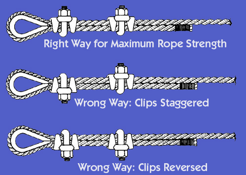
|
MIA: M/SGT James W. Holt USSF 2-7-68 SVN
"Your freedom to be you includes my freedom to be free from you."
-A. Wilkow
"Your freedom to be you includes my freedom to be free from you."
-A. Wilkow
|
Originally Posted By RED_5: is that cable clamp on correctly? So few of them are installed correctly I don't worry about it anymore. Still looking for corrosion, cracks/metal loss, fraying/birdnesting (on the cable, not the peep-peep kind), etc, and if I see something concerning there then I'll recommend it be replaced and notate the incorrect application of saddle clamps. But if it's wrong and still works? IDG much of AF. That cable is part of a hazer system that had far more concerning things than a cable clamp installation. Grounding's the same thing. I can't tell you how many towers i've seen that don't have conductors pointed downwards, exceed minimum bend radius, using incorrect hardware, incorrect wire size, etc etc etc. Could I nitpick on NEC vs R56 standards and make a list 3 pages long of things that are "wrong"? Yes. Does it really matter? Most cases, no. |
|
Originally Posted By AnalogKid: This is a bump, eventually with pics. Nephew gave me a Dell R810 a while back. 512GB memory and 6 1TB drives. It has a 4 socket motherboard and can run up to 40 cores worth of CPU. Hmmm...what to do with this thing. Besides using it as a space heater for my somewhat chilly main office, how about a large VM host? I currently have a number of XP-Pro, Win7-32 and Win11 VMs scattered across a bunch of systems for purposes of receiver/transceiver/peripheral control. 12 discrete PCs plus several management systems. These feed an equivalent number of ceiling mounted monitors. Doing some digging, I came up with a 4-port HDMI card and 8 port serial card, all in PCIe. 2ea would give me 8 video and 16 serial devices, with each VM getting 1 and 2, respectively. The challenge is to NOT boot off the HDD RAID array. That's for warm VM storage only. Have to boot off SSD or NVMe, and run my VMs off NVMe. The 11G mobo doesn't support NVMe boot but there are ways to skin that cat. More to come. Bump. I successfully got the unit configured with xcp-ng as a hypervisor along with XOA, Win11 Pro and Linux Mint 22 VMs. Here's some notes. Which I'll turn into a full-blown how-to at some point: To get graphics cards, serial adapters and whatnot recognized by the VMs, you HAVE to use PCI pass-through. This means a given graphics or serial card is not available to any other VM. Additionally, if you want mouse and keyboard input you have to use a separate PCIe to USB adapter and block its its UUID from the hypervisor. The server's onboard USB HID devices simply won't be passed into the VM. Let's see...two VMs equals two graphics cards, two serial cards, two USB cards...and I haven't even plugged the NVMe adapter or the server's RAID card in yet. I'm out of slots. The solution is simple. Find two two-port USB cards. One port hooks to an 8-port USB to serial adapter and the other to the KVM via SIP device. To get KVM video you use a powered HDMI splitter. Input hooks to the Primary port of your 4-port graphics adapter card and mirrors that display. Output goes to an overhead mounted display (same as HDMI 2 through 4). This works nicely in Win11 with a GeForce GT730 and NVidia drivers. On Linux...I have to use another solution. No matter what I do I cannot get the NVidia Linux driver to detect connected displays, though it initializes properly and when booted, Win11 sees them just fine. Wavlink (DL7400) and Matrox M9148 cards are inbound for experimentation purposes. Boot: I don't want to boot off the RAID array as it's slow as heck compared to SSD, and I don't want to give up one of the NVMe slots to the boot volume. So...what to do? Dell servers have something called an IDSDM which essentially is a RAID0 CF drive array. One can set the utility REFINE up on that pair for UEFI service boot - then pull the optical drive and put an HDD in its place. Caveat: A regular SSD WILL NOT work here as it expects +12v in addition to the +5V suplied by Dell's ODD cable. There is a solution: Swap the ODD for a drive adapter, then get an M.2 to SSD adapter and mount it inside. You don't need a lot of space to install the hypervisor (128GB is definitely adequate); a spare drive of that capacity was secured in the adapter and a heat sink placed atop it. I used REFINE to command a boot from the hypervisor installer on USB stick and put it on that device. BIOS returns a SATA HDD Failure when cycling through POST but the system comes up just peachy. The VMs themselves will be Type 2 hypervisors, using VirtualBox to run FreeDOS, Win-XP or Win7 VMs which control a bunch of radio peripherals. The Win11 VM will also run two or more instances of ProScan natively. What we get here is essentially two separate PCs with enough horsepower left over on the hypervisor for a whole bunch of headless or Console access VMs. Let's expand it further: Throw an R740 or other server in the rack with at least 40 cores, 512GB RAM and 8 PCIe slots. We then have enough resources to emulate 3 PCs, drive 12 monitors simultaneously and host all the service VMs I mentioned. I can control a total of 24 RS-232 based receivers or peripherals this way. And further: I have two antiquated ATX towers in the corner of my office. Swap one of these out for a T630 with 512-768GB RAM and 48 or more cores. We put 7-port USB to PCIe adapters in this - total of three - and pass the entire PCIe devices through to their VMs. Given the fact I'll only be able to drive 12 monitors total, we hook 4 SDRs up to each USB card and run each instance of the program on a dedicated screen via passed-through graphics cards. The HDMI adapters I mentioned have audio devices embedded so the monitors can recover and project the receiver audio - or I can send it to another PC/instance for processing via a virtual audio cable or media streaming app in the VM. I'll still have two ports per card/VM for control of a transceiver like my IC-7200 or USB sound interfaces such as a Signalink. Or a USB-RS232 adapter. Probably not too many other setups like this will be in existence when all is said and done but if I can let the computers do the grunt work I'll be glad to. |
|
The above exercise has proven very challenging but I made major progress yesterday and today. Three different add-in video cards were tried:
All are 4-port PCIe cards. All are passively cooled (requirement for residing in a server chassis). The Matrox would not load a modesetting driver properly in Linux and in Wndows 11 its OEM-provided driver pooched the VM so badly that I had to repave it. The other cards worked well in Windows 11 so I knew the hardware stack was functional. Linux...we fought tooth, fang and nail. I have two different instances of Mint 22.3 on my hypervisor and each is assigned a different video/USB card. The Wavlink (evdi driver and DisplayLink manager) instance initializes but detects no screens. I created a new 22.3 VM today, assigned the GT730 card to it and instrumented each subsequent step of the configuration process. Nouveau drivers (which ship with later versions of Mint) find the monitors via EDID but wouldn't initialize them. I got ahold of the NVidia 470 series OEM driver after installing a 6.8 kernel and installed it. It ran but didn't initialize the screens. I started digging around the Net and found a couple blurbs about forcing those drivers. Of particular note was the "BusID" argument. In Xen Orchestra my assignable PCI IDs for the GT730 are 08:00:0 (audio portion) and 08:00.1 (video) via lspci. However...in the VM, the video device shows as 09:00.0. On a hunch I created a conf file with BusID of "PCI:9.0.0" specified, restarted the system...and Bob's yer video uncle. Going to try this in the other VM with the Wavlink drivers. What it appears to be is a bug with xcp-ng's pass-through framework and I've got a thread going on their forums with such. My 8-port USB-to-serial device arrived today and after attaching it to a passed-through USB card I see ttyUSB0 through 7. So now the VMs can talk to all the radios... |
|
Originally Posted By killingmachine123: I'm going to try and make one of these: https://drive.google.com/file/d/1LwSbXXeovjJdT8ijpOi-9FYR--nNsxgD/view It's high time I make an antenna for the setup I have. I've never gotten myself on the air for HF, only used other people's rigs. Greg's (KJ6ER) antennas work very well. He has a whole slew of designs available, but the performer is the one to start with. It is forgiving and easy to setup. If you have hard rocky or gravel ground,, like I do, spikes don't work so well, but any kind of tripod you can dream up works. The angle of the ground radials is not that important, they need to angle down to improve the SWR. I have been playing with his Marauder antenna, and it works very well. It is single band but is directional and has over 3 dB gain over the single performer. Marauder Link Lets see pictures when you get it up! |
|
More bump on my earlier posts: Apparently, nested hypervisors don't play well when you start mixing them. Nor do the video cards I selected for this test. So... Where I'm at now is a Linux installation right on the server itself and a Type 2 hypervisor (either Virtualbox or QEMU) handling VMs. Had to add a PCIe to NVMe adapter to the setup and move the boot drive to it as the internal SATA connection is a bit flaky when running anything except xcp-ng. Also need higher-end adapter cards (incorporating PLX) to add more than one NVMe drive as this chassis doesn't support PCI bifurcation. They're inbound. Video cards...went a different direction there. System now incorporates AMD Firepro 2460 (4 head) and W600 (6 head) for a total of 10 displays. One of these is used as the KVM display. 8 more are displays for the radio control software I'll run in the VMs and the 10th will feed a system monitor for keeping an eye on CPU/GPU temps. Concept will be expanded to a T630 and R740 when I can find them for a total of 16 displays each. Two W600s and a 2460 there. They just work. Now the process of upgrading the RAID array and buying M.2 NVMe drives begins. |