


Posted: 8/15/2007 6:01:08 AM EDT
 We got our FT 2800s in and I've been playing with em when I have time. I made a copper pipe slim jim and had a heck of a time getting the SWR down but finally got it to 1.3:1 Once I realized I was leaning the antenna against the kitchen wall with the stove and fridge on the other side I moved it out to the middle of the porch and used my sons plastic Basket ball hoop to prop it up and things settled right down.  Sunday night I tried setting it up in my Jeep. I took the fiberglass antenna I had been using for my CB, stripped the plastic covering off the windings and trimmed the wire down to 49" for a 5/8 wave and then started trimming and measuring SWR with a Royce model 2-100 SWR meter. I just couldn't get it down below 3:1. When i figured I'd taken too much off for a 5/8 wave I cut it down to 19" for a 1/4 wave, i had more luck but not great, I was able to get it down to 2.1:1 at 5 watts but that was it. When I tried turning up the power to 10 watts, the SWR went to 3:1 and when I turned it up to 25 watts it pegged the needle I've got the antenna mounted on the back with a generic mirror mount.  This is my first time playing with something other than CB, is SWR supposed to increase with increased power? Is there something I'm missing about my attempt at making a mobile antenna? shouldn't a cut down Firestik work if I get the length right? |
great post! a lot going on here... and all of it is good. i'm delighted to see that you have jumped into amateur radio antenna construction and experimentation with both feet. you are a little off course in a couple of areas, but we can fix that up quick.
how did you measure the SWR? the reason i ask is because...
the Royce model 2-100 SWR meter is designed for CB frequencies (~27MHz). it probably will not give you a good indication of SWR on the 2M band (~146MHz). this is due to the fact that the design of the directional coupler inside the SWR meter is very different once you get above about 100MHz. i would not put too much stock in the SWR readings you took with the CB band SWR meter. the readings may be about ok or they may be wildly off -- you just can't know.
you can't directly end-feed a 5/8 wave element -- you need a matching element (physical, like stub, or electrical, like an LC network) at the base. for example, the SLIM JIM that you built has a 1/4 wave matching section at the base, because like the 5/8 wave, you can't directly end feed a 1/2 wave element either. so you have at least two issues with your 5/8 wave antenna experiment: (a) the CB band SWR meter is likely lying to you to some extent, and (b) the 5/8 wave element alone does not present an attractive impedance.
this is a characteristic of the meter. the SWR presented by the antenna (any antenna) does not change as a function of power (at least within reasonable limits of power i might add -- but if you shove 1.5KW into a mobile antenna designed for 100W i can pretty much guarantee you'll get a different SWR!). with a whiteboard, marker, and 10 minutes i could explain why the meter reacts the way you are seeing, but i'll give you the cliff notes version. SWR is a ratio of forward to reflected power. forward power (good) is going from your radio to the antenna. reflected power (bad) is coming from the antenna back to the radio. an inexpensive SWR meter usually has a single needle, and this needle represents at a given power what the SWR is. this type of meter will also have a switch which toggles the meter from "power" measurement to "swr" measurement. to get the real SWR value, you first measure the input power, then toggle the switch over to SWR. key again, and take the uncorrected SWR reading. on the back of such a single needle meter will be a correction curve -- you must find where the measured power and the uncorrected swr interesect and that will be the corrected SWR.  (your CB band SWR meter, note, probably does not have a correction curve on the back side -- this is because CB's are fixed at 4W output and therefore the input power should be in that ballpark. hence, no correction is needed.) another, more expensive type of SWR meter approaches this differently. it is called a "cross needle" SWR meter. this type contains a meter with two needles, and the forward and reflected power are shown simultaneously when you key the TX. via information inked behind the needles, the intersection of the two needles shows the correct SWR, regardless of applied power. the cross needle SWR meter, therefore, is concurrently more straightforward to use and more accurate than a single needle meter.   finally, another type of single needle SWR meter has a "CAL" (calibration) dial on front. with this stype, you flip a switch to CAL, key down, set the dial so that the meter is full scale, and then flip the switch to the SWR setting. the setting of the CAL dial does the input power correction that you'd otherwise have to do manually.  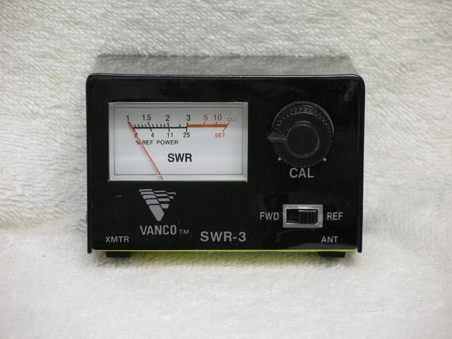
at 1/4 wave, it will work with some limitations. a 1/4 wave antenna relies on the underlying ground plane to make up the other half of the virtual dipole. the way you have the antenna mounted above, there is very little ground plane under it, and it is asymmetrical as well. this will cause two issues -- poor SWR and non-uniform radiation pattern. hope all that helps. keep trying stuff! ar-jedi |
Thank you, I'll likely never have the knowledge necessary to build my own radio but I like the idea of building as much of my gear as possible.
According the manual that came with the unit it's supposed to be good for 3.5MHZ to 150MHZ Are they fudging the numbers?
That would explain a bunch, thank you. The Cb antenna I used claimed to be a 5/8 wave that's why I figured that would be a good length to go for.
Jeeps offer poor choices in mounting locations, but I didn't realize it would adversely effect SWR readings, I get a good match with my CB antennas. I also tune the antennas for most of the guys I work with driving big trucks and we have similar mounting issues there. I knew about the directional issue, with my CB I get best signal forward and left. I'll see if I can come up with a mount for the windshield frame, I was hoping to keep the antenna as far from me as possible.
It helps alot, thank you |
hmmm, ok, so perhaps it does do 2M. questions... is there a CAL knob? is there a SWR vs power correction chart in the manual or on the unit?
there is probably a loading coil or matching network in the base of the CB antenna -- this would of course greatly hamper your efforts to get the now cut antenna element to sit down SWR-wise at 2M since the matching network doesn't want to play at 2M.
good observation.
try a half wave 2M antenna design -- the half wave will be much less dependent on the mount underneath it. the Comet SBB-5 comes to mind -- it is an excellent antenna. www.universal-radio.com/catalog/hamantm/3910.html don't forget that most all ham antennas require the separate purchase of the actual mount, typically magnetic, NMO, gutter, mirror, etc. aside, since you seem to be proficient with a torch, you could sweat up a 1/2 wave J-pole from 3/8" or 1/2" copper pipe, and try that at different locations on the jeep. it may look a little trailer park-ish, but it will work. ar-jedi |
|
One thing to keep in mind when trying to measure SWR is exactly what you are measuring. Professionals don't use SWR, they use RLR, which is (Return Loss Ratio) - basically comparing the power put into a cable to the power that comes back out of it (reflected from the load). What SWR measures typically is the voltage of the two signals, one going to the load, and the other coming back. The problem is in what you are trying to measure is a standing wave -- which is caused by the interference between the transmitted and reflected signals. This will vary depending upon the point along the feed line at which you measure. With longer wavelengths (e.g. 27MHz) and short feed lines, this isn't much of a problem. At VHF/UHF it is a big problem. If you put a variable length of cable between your SWR meter and load, as you vary the length, you will see the SWR reading change. At some length of feed line it will actually show 1:1. You could connect your TX at this point and it would be happy. But it wouldn't mean that all of the power is actually making it into the load. I know it can be a pain to do, but life is much easier if you put your SWR meter close to the load (antenna), rather than close to the TX. If you can't do that easilly, as a final check when you think you are done, add a bit more cable between the SWR meter and the feed line and check to see that it still reads a reasonable value. |
[disclaimer] I'm admittedly in over my head on the technical side of this discussion [/disclaimer], but just wanted to throw one little thing in the mix. There are at least 2 things you're going for in the effort to minimize SWR: 1) Maximum signal radiating from the antenna and 2) Protecting your radio from damage from reflected power. So remember even if you're able to get the meter on the load end of your path (close to the antenna), all the radio cares about is the impedance it sees at the antenna jack. So regardless of what you test "down the (feed)line" in the end you verify what the radio sees (SWR) to avoid damage. I imagine most anyone would do this anyway, but just wanted to quantify both goals of SWR adjustments. 73, and as Jedi said, kudos for the homebrew experiments! |
Well, there is merit to that idea. But it depends on what you are looking for: - A load (antenna) and feedline combination that matches your TX. - A load (antenna) correctly matched to the feedline. Either will work, and in a mobile setup, for practical purposes there is no difference. (Provided you can maintain the match over the frequency range of interest). But in a setup with a long feedline it will make a difference to the amount of energy you put into the air (where you want it), vs into heating up the feedline (where you don't want it). |
|
Everything technical aside, you should pick up a 2 meter 5/8 antenna at a hamfest or from Firestick. They make ham antennas that fit a 3/8-24 fitting like whats on your jeep. Also, put in a new run of coax to the mount. I ran a similar setup on my 78 Bronco for years and never broke it off. The SWR was always about 1.8 (10% ref)on it, but that won't hurt the radio. You could get by with a cheap ($15) mag mount on your front fender/hood area. At 2 meters, (146 mhz) you don't need a whole lot of ground plane versus CB. If the SWR is changing with the output power, you might have a bad piece of coax causing RF to come back to the radio. Good luck, RS |
www.westcoastmall.net/vanco-swr-meter/859/p This is the exact same unit I have but with a different name. There's a single needle meter with SWR and percent reflected lines and a lower line for feild strength. There's a FWD/REF switch and then a tuning knob. I don't see an SWR vs power chart anywhere.
I've been considering making a roll up J pole inside a piece of pvc pipe to use on my semi, I drive a Volvo and the idiots put plastic mirrors on it 
|
|
I have found that the SWR does in fact increase markedly with increased power, at least under certain circumstances. One of the ways that this manifests itself is when using a 20 meter dipole for other bands. I can tune it to many different bands, as long as I keep power down real low. The vertical antenna on my vehicle behaves similarly. It has been acting so oddly these past few weeks, that I intend to swap out the coax this weekend. Suspect that it has degraded or otherwise been damaged. |
That is indeed what I suspect with my own installation. Should not have come as any surprise, as I blatantly disregarded the minimum bend radius limit of the coax. <slaps head> |
|
Funny I have been looking at SWR meters this morning. Seems you need a couple since the frequency coverage varies so much. For example, this meter would be great for building a Jpole for a HT that covers 6m, 2m and 70cm, but you couldn't use it later when you upgrade your ticket and start playing with 10m. Am I wrong? ETA Seems like for $85 bucks this would be the daddy  |
|
Random observations... www.k1cra.com/catalog/product.aspx?productID=1357 3/8" mount 5/8 wave antenna for 2m. $12 + shipping, it's just not worth the trouble trying to calculate, modify, test, tune, etc etc a CB whip. If you want to experiment you'd probably have an easier time starting from scratch. There's also a 5/8 over 1/4 wave antenna (Hustler CG-144) which would be taller and might give you a little better signal from that installation, but it's pretty tall at 7'1". Second, why the "trombone" radiator section on the J pole? Just wondering why the extra element there which really isn't doing much to improve the radiation of the antenna. If it was vertical above the first element and in phase (colinear) then you'd get an increase in gain. I'm also wondering how you plan to mount that antenna to anything... For real antenna homebuilding/experimenting you really want to get some kind of antenna analyzer, like this one from AEA, or MFJ has a similar product without the graphical display. They are expensive but really make it easy to design/build/tune. ETA:
The ARRL antenna handbook has a simple idea/design to make a 2m J pole out of a mobile CB long whip. Something similar could be homebrewed very easily and would be much stronger than a copper pipe J pole. |
I pretty much am starting from scratch, when I get it all stripped down all I have is a stud mount, a fiberglass rod and a buttload of wire. I wanted to do this so I could get the satisfaction of saying I built some part of the installation.
I originally went looking for J pole plans but ran across this. They claim that extra element keeps the radiation pattern closer to the ground. www.hamuniverse.com/2metercopperslimjim.html I figured I could simply hang it in the attic.
That would be nice. |
If you have loading coils on your verticals check those carefully first. Buddy told me that most verticals fail there first. skeeterah -I have a slim jim dipole in my attic I use for 2m. Works great. I can hit repeaters 30-40 miles away with it @ 50w. |
|
I strongly suspect that the problem is indeed at least partly due to the loading coil on my antenna beginning to fail. SWR and/or RF feedback gets markedly worse as the coil heats up. With temps as hot as they are around here, that does not take long. Also, removing several feet of coax from the installation has helped tremendously. The SWR now reads around 1:1 plus or minus a few KC's, just like it did when the installation was new. Odd thing is, is that I added the several feet of coax to the installation during the initial installation because it appeared to alleviate an RF feedback problem at that time. Dunno what changed. As long as the antenna doesn't get too warm, everything seems to be working now. A hundred watt key-down on FM for about thirty seconds will apparently overheat the antenna. Along with getting a replacement antenna, I think I might try one of those in-line vehicle baluns as sold by MFJ. |
What frequency band is this? What type of antenna construction? |
40 meters. The antenna is a Pro-Am monoband vertical. Commonly referred to generically as a "ham stick". Vehicle mounted. I am using a "WD4BUM Inducti-Match" to help match it, along with using a brand new LDG Z-100 auto-tuner. The latter is mainly for the purpose of increasing the useful bandwidth of the antenna. It works when it isn't hot. I just chatted with an Ohio and a Texas station a couple hours ago. |
|
Just tried the antenna on the back of the wifes Wrangler, we did a new CB install on her rig a couple months ago so she had new coax and mount. We got 1.4:1 with no adjustments so I think it may be the coax as suggested. I'm still getting an increase in SWR as I crank up the power but I have a feeling it's just because I'm using a cheap meter. I took the Jeep for a spin with my wife home using the hand held. I got about 5 miles away before I began to lose her, as I turned around she was still talking and the signal got significantly stronger. If I mount this to the top passenger side corner of the windshield frame, do you think it'll still be that directional? I don't want to mount it in the center since I carry stuff up there at times. Anybody have any experience with Wranglers? Next problem, how much are we going to be cooking ourselves? mounted in either location the antenna will be no more than 4 foot away. My wife has a fiberglass hard top but I just have a soft top. The radios do 5, 10, 25 and 65 watts. |
|
skimmed thru the posts and didn't see if the cut down Firestick was still wrapped around the fiberglass rod? if it is still coiled around the fiberglass pole it will act more as an inductor/heilical wound antenna, IIRC a heilical wound antenna will have different dimensions than a 1/4 wave whip. try unwinding the copper wire and straightening it out and cut it about 19 and 3/4 inches and trim from there. you can also get an adapter from most "shops" that will screw in place of the antenna and will accept a 1/8 in stainless whip. |
|
We got everything working fairly well and have been using the radios for a few weeks but weren't getting the range I'd hoped for with the cut down firesticks. Last weekend we went to a hamfest and found a couple 5/8th wave stainless whips for a good price. When we installed em I checked SWR and it was good on my Jeep but over 2 on my wifes. we tried adjusting whip length, we tried rerouting coax, we tried moving the mount. At one point we got it down to 1.6 with the antenna on her cb mount but obviously didn't want to eliminate her cb so we kept trying. Nothing seemed to work so I put it back on the cb mount till I could come up with something else, I checked SWR again just to make sure and it had gone up over 2 again. I stuck her cb antenna back on and checked that, it was over 2, we had a perfect match on that when we installed it a couple months ago. This is driving me nuts and it's really getting frustrating for the wife |
|
PL259/SO239 type connectors are not weatherproof, and you have no weathersealing on the mount that is pictured. Also, the coax cable has an extemely tight bend which is bad news. And, you have little in the way of ground plane there. What I would recommend as a test is to use a 90 degree adapter on the mount, and then a different coax jumper to the radio and see if that solves your wandering SWR problem as I suspect you have coax problems. I suspect that you'll end up changing the coax and if so you really need to weatherproof the connections (both ends of the 90 degree adapter). ETA:
Incorrect. SWR should be measured at the load if you want to correctly analyze what is happening with the antenna without the effects of the feedline. Testing at the radio is kind of an overall system check but a poor choice when you're trying to adjust an antenna. |
|
Different Jeep, the one pictured is mine and works good. That's actually my cb mount, the 2 meter antenna is now mounted to the windshield frame on the passenger side. My wifes Jeep is newer and in better shape. We replaced her coax and tried all the antennas on my Jeep where they worked fine. We stuck my radio in her Jeep to make sure it wasn't a problem with the radio itself. Everything works on mine, nothing on hers. |