


Posted: 11/9/2017 11:32:08 PM EDT
[Last Edit: Jupiter7200][Edited]
|
OK, let's make a simple dipole. If you only have one dipole, I suggest you make it for the 40 meter band. This band works most of the day, sometimes all day, and well into the evening. 40 meters is a good regional band, reaching several states away, and there are many active nets there, too. (EDIT, I have talked to Ireland and Scotland on 40 meters at 01:00 local time, which was 06:00 their time. Gray line?) The 66' overall length can easily fit in many back yards, and with a little help from a tuner, can also work 15 meters for some good DX. I'm going to show a few photos of how to assemble a good, rugged dipole that will work as well as any commercially made one, and is probably better constructed than most. Here's where we start, with the Jetstream JTCE1 center insulator. This one happens to be green, but they come also in black, gray, blue, and white. Black disappears against foliage well, so if you have a nosey HOA, but have trees behind you, black works well. Attached File I won't go into step by step, except to describe the components. The clamps are small stainless cable clamps from True Value. Some are not stainless. I found these in the marine section. Try marine dealers for these in stainless. While there, pick up a good marine grade pulley, rather than a cheap one that will corrode and freeze up. Edit: Check out the OCFD thread I posted about use of copper split nuts instead of these clamps. In this case, the wire pigtails from cable clamps to the ring terminals are about 5" long. I both crimped and soldered the terminals, which come with the Jetstream insulator. The JTCE1 has beveled holes that won't cut through the wire or rope used to hang the insulator. Good thinking on Jetstream's part. The same center insulator can also be used to make a fan dipole, and more bands can be added later. Another thing I like about this center insulator is that it is easy to wrap the SO-239 / PL-259 with coax seal, silicone tape, or other sealant method. I put a drop of blue (removable) Locktite on each of the nuts on the cable clamps, and also the nuts on the terminals. There is some silicone dielectric grease smeared on the ring terminal before assembly. |
|
Measure from the center of the insulator out to where you will place your end insulators. I know that the pigtails (they are 5" long, leave some slack here) going to the terminals add a little more length, but we will take care of that when we trim the antenna during testing. Attached File This center insulator may be obtained from Amazon. https://www.amazon.com/dp/B07FKVM8XV |
|
Edit: Once again, refer to the my post about making OCFD's. Here is one of the end insulators. It is also found at Universal Radio listed simply as C150. It looks like a generic electric fence insulator. Use any kind you like, but these are cheap and effective. http://www.universal-radio.com/catalog/antsup/4818.html Attached File Again, a drop of blue Locktite on the cable clamp nuts is a good idea. You can get these at Tractor Supply in either yellow or black. https://www.tractorsupply.com/tsc/product/zareba-heavy-duty-corner-insulator-yellow-pack-of-10 and https://www.tractorsupply.com/tsc/product/zareba-copper-split-bolts |
|
Measure length of each leg from the middle of the center insulator, as shown previously, to the farthest reach of the wire in the end insulator.
Attached File Wire used, in this case, was 14 ga stranded insulated THHN. This antenna is being built for my club, and is what they had. I prefer MTW, but this wire is fine. Calculate the overall span of your 1/2 wavelength dipole with the formula 468 / frequency(in mhz) = overall length in feet. So, for 40 meters, centering the frequency in the band (7.000 - 7.300 mhz) at 7.150 mhz, we get 468 / 7.150 mhz = 65.45' So each leg will be 32.73'. I would add a few inches for the 40 meter band, and measuring as shown above, make each leg 33'. We will adjust/correct for any error during installation. |
|
This is our end result.
Attached File This one happens to be cut for 3.900 mhz, the center of the 75 meter phone portion of the 80 meter band, but construction for any other frequency is similar. I made each leg 60.5' long, overall span 121'. We will trim that a bit to get it up to 3.900 mhz by trimming the ends. 3.900 mhz should be 120' exactly, but it is far easier to take a few inches off than to add a few inches if too short. There are other center and end insulators. Split bolts may be used in place of the cable clamps. But this is one way to make a good, strong, long lasting dipole. An analyzer will make trimming fast and easy. We will hang the dipole, check with the analyzer. Let's say we find lowest SWR is 1.15:1 at 3.869 mhz. We know overall length now is 121'. We will make a ratio and solve for the new length. ( Actual frequency / Frequency desired) x Present Length = New Length ( 3.869 mhz / 3.900 mhz ) x 121' = 120' 121' - 120' = 1' to be removed, or 6" removed from each side. Do this, and you'll be right on the desired frequency. Edited - related threads you may want to read. Let's Make an OCFD https://www.ar15.com/forums/outdoors/Let-s-Make-an-OCFD/22-690848/ Centerfed Dipole vs. OCFD https://www.ar15.com/forums/outdoors/Centerfed-Dipole-vs-OCFD-Windom-sic-/22-690849/ |

| Nice pics and documentation! Plenty of guys live on 40M, I'd say, and that's perfectly fine. This would be a great, long lasting option for those guys. I've been trying to get my Dad onto HF. He's had his General for years, but I just can't seem to get him to bite. One of these and that old TS-50 sitting on my bench would make some great contacts. Good work! |


|
Suggestion: don't bother with the cable clamps or split bolts. Not that they aren't terribly expensive, but you really don't need them, and if you avoid them you don't have to worry about them cutting through the jacket of your wire or becoming a stress riser because the wire can't bend at that point.
Instead, just tie an appropriate knot in the wire: - Pass the wire through the insulator or wire support - Make 5 or so tight turns around the standing end of the wire - Bring the running end of the wire back through the area next to the insulator and then back though itself, i.e. make and overhand knot over the top of the tight turns. It's much easier to understand with a photo 

I've never had this slip or break. It works fine with 12 or 14AWG THHN, and with 13AWG copper clad, too. I do keep a few clamps around to use temporarily while tuning the antenna, but I always use this knot on the finished product. You can use a cable tie or two to keep the running end of the wire neat, if necessary. |
|
Originally Posted By aa777888-2:
Suggestion: don't bother with the cable clamps or split bolts. Not that they aren't terribly expensive, but you really don't need them, and if you avoid them you don't have to worry about them cutting through the jacket of your wire or becoming a stress riser because the wire can't bend at that point. Instead, just tie an appropriate knot in the wire: When using this knot, just ignore all the wire in the knot. Don't try to account for it. |

|
A 40 Meter dipole can be used on 15 Meters with an antenna tuner. The match is less than optimal, but can be improved by placing capacity "hats" about 11-1/2' each side of the center insulator.
To make the "hat", solder the ends of a 2' wire together to form a loop, then twist the loop into a figure 8 and install on the antenna. Adjust the position to minimize SWR around your favoritre operating frequency. With Cycle 24 nearing its minimum, 15 Meters does not open up often, but when it does, it can offer excellent DX. |
"The inherent vice of capitalism is the unequal sharing of blessings;
the inherent virtue of socialism is the equal sharing of miseries."
Winston Churchill
the inherent virtue of socialism is the equal sharing of miseries."
Winston Churchill

|
I have discovered that when making a fan dipole, if you terminate the ends of each wire about 20 degrees from the others, there is a lot less coupling of the wires. Ans 20 degrees does not really change the orientation of the radiation pattern much at all.
I also use 1/2 inch PVC pipe cut to 3 inches and holes drilled for wire and parachord for insulators. Much cheaper and works just as well. An 8 foot section will make many insulators |
Mach
_______________________________________
Most of my posting is from my phone. Hence the fat thumb spelling errors.
Drain the swamp
.
_______________________________________
Most of my posting is from my phone. Hence the fat thumb spelling errors.
Drain the swamp
.
|
So what if you cut a dipole too short? If you twist and solder on another few inches or feet on the end, that joint will be a weak spot likely to break in a storm. See the little stub sticking off the end insulator? Attached File Add a foot or two soldered to that little end stub, and just let it hang down, say, 1' each end on a 40 m dipole, and 2' on each end of an 80 or 75 m dipole. Now, check for resonance, and trim off a little from each end, check again. When you get it where you want it just let those end pieces hang. Or stretch them out along the end ropes, and secure with Ty-Wraps. |
|
Jup's "line stretching" method works great. In fact I used it myself on my latest inverted L build. However, to avoid the soldering iron, or the crimper, consider using some wire nuts. No, really...
Tie the extra wire to the wire side of the insulator using one of my "fishing knots" (and I looked it up, it is an "improved clinch knot"  ). Then just use a wire nut and wire nut the wire tail ends together. A little dab of RTV in the bottom of the nut will make things nice and weather-tight. This method, because it anchors the wire to the insulator, is good for adding large pieces of wire. This is how I turned my 80M dipole into a 40M half square, simply by adding some 40M quarter wave vertical elements on the ends of it. ). Then just use a wire nut and wire nut the wire tail ends together. A little dab of RTV in the bottom of the nut will make things nice and weather-tight. This method, because it anchors the wire to the insulator, is good for adding large pieces of wire. This is how I turned my 80M dipole into a 40M half square, simply by adding some 40M quarter wave vertical elements on the ends of it.
If you are adding a relatively long piece of wire then remove the guy rope from the other side of the insulator, tie the wire onto that side, and again wire nut them together. Then add another insulator on the end of the new wire segment. This is how I lengthened my inverted L from 125ft to 155ft without having to do the entire thing over again or waste the 125ft I already put up there. Wire nuts are also a lot easier than putting terminals on the ends of the wire and fussing with a bunch of stainless screws, washers, locknuts and the like. If you are homebrewing a center support, or balun, just bring out some flying leads and connect things up with wire nuts. With some RTV in the bottom they are arguably far more weather resistant than ring terminals out in the open. 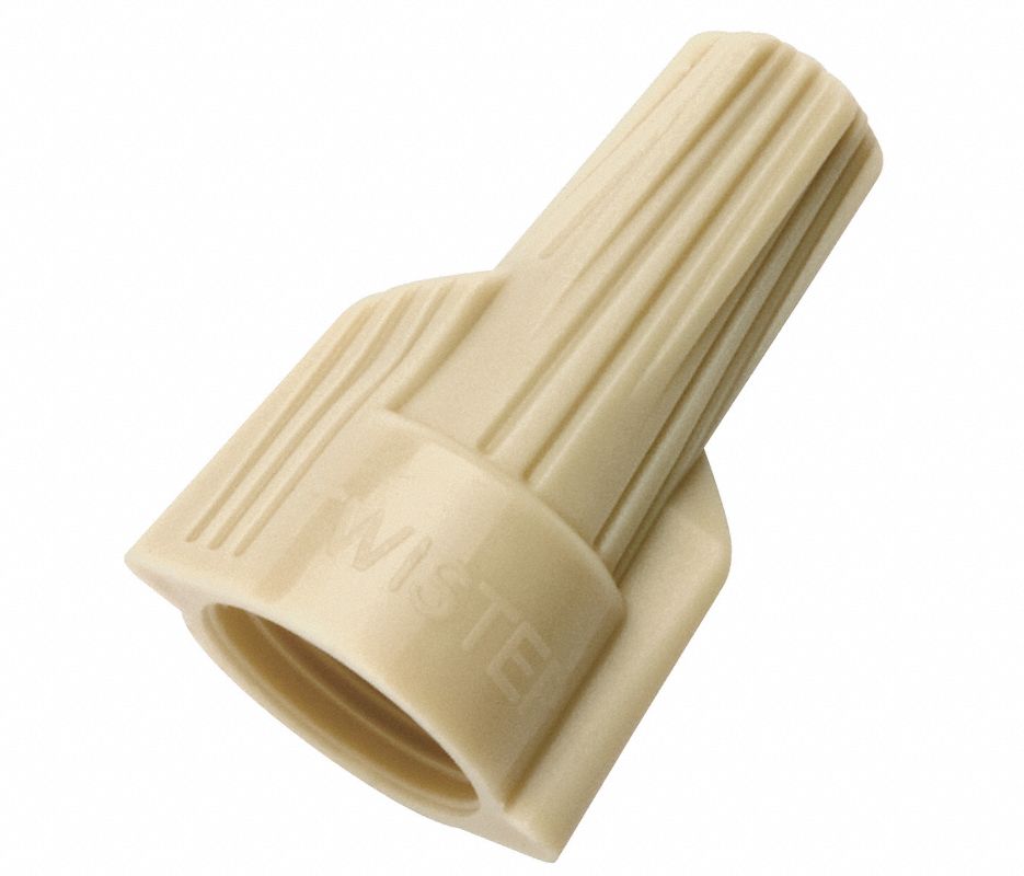
|

| lenght calculator |
http://piccoloshash.blogspot.com
Vote "YES" on 'NO'!
For Captain Erick Foster, Wexford, PA KIA 29 Aug, 07.
Rangers lead the way.
Inspected by #26
Vote "YES" on 'NO'!
For Captain Erick Foster, Wexford, PA KIA 29 Aug, 07.
Rangers lead the way.
Inspected by #26

|
Originally Posted By Fullpower:
When using a common feed point for two dipoles, let's say 75 and 40 meters, what " Detuning" is observed ? Is there a rule of thumb about how much longer each wire needs to be cut ? the shorter wires couple the most to the longer wires so for an 80/40/20 fan dipole tune the longest wire first 80 m then tune the next longest 40 m then the 20m Also I just twist the excess wire around the non-excess wire. It stays put just fine and you always have excess wire to make the antenna longer if you end up tuning it to short. also pvc insulated wire ( home depot thhn ) will be shorter than bare wire by about 4%. so 468/ freq in mhz x 0.96 in a fan, the shorter band wire will be even shorter because it couples to the longer wire. |
Mach
_______________________________________
Most of my posting is from my phone. Hence the fat thumb spelling errors.
Drain the swamp
.
_______________________________________
Most of my posting is from my phone. Hence the fat thumb spelling errors.
Drain the swamp
.

Black on ammo due to celebratory fire.
Joined:
Apr 2007
Posts:
16480
EE: 100% (48)
 AZ, USA
|
For this particular 64' dipole.. What height realistically does the insulator need to be to be effective?
The updated link to the insulator in the op is now here: https://www.universal-radio.com/catalog/antsup/2896.html (old one was discontinued) I'm not familiar with the height calculations, and the manual didn't state anything. 
My options in my yard are running this from 8ft tall cinderblock to cinderblock walls, inverted V off a 25ft tall point on the top of my roof to the ground, or running this lengthwise across the top of my roof at about 18ft above ground. Would any one of those options be preferable? |
No angel flies with me tonight..

|
excellent thread I always skin back and solder around the insulators Kinda like this pic stolen from googles Attached File |
NRA Life Member
USPSA-IPSC
Phuc cancer
I liked this place a lot better when it was a gun forum.
USPSA-IPSC
Phuc cancer
I liked this place a lot better when it was a gun forum.

|
Originally Posted By unpleasant:
For this particular 64' dipole.. What height realistically does the insulator need to be to be effective? The updated link to the insulator in the op is now here: https://www.universal-radio.com/catalog/antsup/2896.html (old one was discontinued) I'm not familiar with the height calculations, and the manual didn't state anything. https://www.universal-radio.com/catalog/antsup/2896man.jpg My options in my yard are running this from 8ft tall cinderblock to cinderblock walls, inverted V off a 25ft tall point on the top of my roof to the ground, or running this lengthwise across the top of my roof at about 18ft above ground. Would any one of those options be preferable? 73, Rob |
|
I have no idea what frequency you want to use. But once you decide... 468 divided by freq (in mHz) = overall length of dipole in feet. Make it, for 40 meters, about 6" longer on each end. Check where SWR is lowest. Trim from there to your desired frequency. 1' longer each end for 80 m dipole, about 4" longer each end at 20 meters. My previous fan dipole, the desired frequency was 3.900 mHz. That calculates to 468 / 3.900 mHz = 120' I started about 122 ft overall. To get it to 3.900 mHz I had to trim, to no surprise, 1' from each end, making it a total of 120'. On the button. |

|
Originally Posted By smeeg: So let’s say you want to make a 40meter dipole for JS8call not using the standard frequency. Your own groups @ chat how would you decide on what frequencies to choose? A full size 40m dipole should cover the entire 40m band at a reasonable SWR. You can of course bias it a little if it's exclusively used for CW/digital or SSB. |
This is...a clue - Pat_Rogers
I'm not adequately aluminumized for this thread. - gonzo_beyondo
CO, MI, OR - Please lobby your legislators to end discrimination against non-resident CCW permit holders
I'm not adequately aluminumized for this thread. - gonzo_beyondo
CO, MI, OR - Please lobby your legislators to end discrimination against non-resident CCW permit holders
|
Originally Posted By CS223: No 1:1 Balun? Nope. EDIT: Let me correct myself. For just a dipole, or fan dipole, at 100 w generally no balun is needed. But I did run into a problem some time back with RF affecting the amp at 600-800 watts. I could back off to 300 w or so, no problem. I ended up with a choke just below the feedpoint and that killed the oscillation. |
|
To add a little wire to the ends to bring down the resonance a tad, these Wago 221 Inline connectors are the schiznitz! Works far better than wire nuts. These were not generally available when I first wrote this thread. They won't hold line tension if placed between center and end insulator. These must be placed past the end insulator on the very end. https://www.amazon.com/dp/B0CR53N1BV Attached File |
|
I'm going to build the WARC and 60M equivalent of a DX-LB Plus with a pair of salvaged loading coils plus a center insulator similar to the Jetstream model. Will write that up here when done. When I had the donor antenna in the air as an inverted vee (DX 80/40) I tuned the 40M section for 7.090. This put the 15M resonance point around 21.300, slightly under 2:1. Didn't put capacitance hats on the sections but I might do that with the LB Plus which replaced it. I need to look at the thing with an antenna analyzer anyway. |
|
Originally Posted By cn6145: Best antenna I've had was doublet cut a little longer than 80 meters and fed with open ladder line to an old MFJ tuner. It blew down in a storm and I miss it! That's almost what I'm running... 130' doublet fed with 450 ohm window line and Ameritron ATR-15 tuner. So far, it's doing well for me! |

|
Originally Posted By Ramcharger_pilot: Do you need to separate the feed ends for a multiple band fan dipole? No, that's the beauty of the fan dipole. Let me back up... my very first antenna was an 80 meter dipole that I used for Short Wave Listening with an Icom R75. I think it was 130' or so. I had the center mast up at about 20' clamped to the wood fence along the side of my lot. The ends sloped down to each end of the fence tied off to eyebolts screwed into the top of the fence. This put the ends up about 7'-8' or so. So it was a big inverted Vee. And that worked for me for a while for SWL. When I got licensed I added two more wires to each side all coming up to the same center insulator. The 40 meter elements were about 32.4' on each side, coming down in a sharper inverted Vee, to two more eyebolts in the top of the fence. The ends of those wires ended up being about 2' below the 80 meter wires. Two more wires added for 20 meters, each about 16.4', a little sharper Vee, with the ends being about 2' below the 40 m wires. There was almost no tuning interaction with the wires separated this much. I shortened the 80 meter wires to tune to 3.900 mhz, the 40 meter wires gave me about 7.2 mhz, and the 20 meter wires about 14.225 mhz. The three wires at the center on each side were twisted together, a little 4" single wire soldered on, with the wire from one side soldered to the shield side of a SO-239, and the wire from the other side soldered to the center conductor of the SO-239. The transmitted RF energy will go to whichever pair of wires is the closest match for resonance. A 7.250 mhz signal will go to the center pair of wires, and the other wires are all high impedance and get little to no energy. Same with a 75 mhz signal going to the longest wires, or a 20 m signal going to the shortest pair. A 21 mhz signal will go to the 40 meter wires as they will resonate at a 3x harmonic. And I could get 17 meters and 10 meters with very little help from the tuner. 12 meters was high impedance, and even the tuner didn't help. But I could use 75, 40, 20, 17, 15, and 10 meters. A fan dipole has "automatic band switching"!!! All with just one piece of coax! I used this fan dipole until jasmine pulled it down and at that time, I was too ill to clear that out and fix it. I stayed off the air for six years. The last entry in my log was in 2018. Recently I cleaned all that out, put up a 130' doublet, 450 ohm window line, a big tuner (Ameritron ATR-15). I added more tubing to the center, which is now about 30'. Added 18' poles to each end, so the whole thing is about 10' higher than my previous antenna. That is a big improvement by itself. Now, I could have done all this with just two wires and a 4:1 balun and coax with an OCFD... Off Center Fed Dipole. Normally a centerfed dipole will not work on even numbered harmonics, that is, one cut for 80m will not work 40m, 20m, 10m. There would be a node (look that up) in the center right at the feedpoint for all those higher bands. But if you move the feedpoint over toward one end you get the feedpoint off the center node and can again drive the antenna, but the impedance is higher. If you have the antenna divided roughly 1/3-2/3 you get about 200 ohms at the feedpoint. 4:1 balun makes that 50 ohms to the coax, and a match. Then it will work the even harmonics. 80-40-20-10. And if you get it to one side or the other of that 1/3 feedpoint, you can get it to work 17 m, too. 15 meters is the tough one. There is a feedpoint that will get the 15 meter band to work, but you lose the 17m band. Well, life is a compromise. |

|
I started with a store bought 20m dipole. Added 40m, then added 80m then added 10 m wires. I tune 80-10m with no problem. I oriented the 80m wires 90 degrees to the other wires because at only 50 feet, there is no direction on 80m inverted Vee. The 40m wire is offset 20 degrees from the 20 / 10 wires to decouple the shorter wires because once again at only 50 feet, there is little direction. The 20m and 10m wires lay N/S so I get a little extra gain in E/W which is bad in summer when those bands go across the north pole long path in day light all night long. I can also tune 6 meters but my autotuner can not do 6m, I have to use a different tuner and maybe someday i will again, but just haven't set it up yet since moving to the autotuner. If anybody knows how to get the MFJ-998 autotuner to be stable on 6 meters please let me know. For 160m I use a 270 ft doublet fed ( extra long so that the antenna is inductive in nature on purpose ) with homebrew almost 600 ohm ( 10 gauge wire at 4 inch spacing ) tuned with a homebrew modified for 160m Johnson Matchbox 1kw tuner, which many consider to be a true balanced tuner but it really is not, close but not entirely because the OEM capacitor on the output in parallel with the secondary coil ( output coil ) has the a butterfly cap with the middle grounded. Maybe someday I will rewire that and fix it, but it was a mistake in the design, IMO. |
Mach
Nobody is coming to save us.
.
Nobody is coming to save us.
.
|
Guys sure do brag (justifiably) about their Johnson Matchboxes! It has a great reputation. For those hesitant about open feeder (true ladder line), 450 ohm window line is a good alternative. There used to be a good spacer kit on the market for ladder line, but they are gone now. A way to do this is with these "4 inch fin tube insulators": https://www.tractorsupply.com/tsc/product/american-farmworks-4-inch-fin-tube-insulators-25-pack You stick a long skinny Ty-wrap through it, around the feed wire, and back through. The tighten it around the other feed wire. You can also pick up these for end insulators at Tractor Supply: https://www.tractorsupply.com/tsc/product/patriot-end-strain-insulator-black-809981 https://www.tractorsupply.com/tsc/product/american-farmworks-jumbo-black-corner-electric-fence-insulators https://www.tractorsupply.com/tsc/product/zareba-black-corner-post-insulator-pack-of-10 |
|
Originally Posted By Jupiter7200: Guys sure do brag (justifiably) about their Johnson Matchboxes! It has a great reputation. For those hesitant about open feeder (true ladder line), 450 ohm window line is a good alternative. There used to be a good spacer kit on the market for ladder line, but they are gone now. A way to do this is with these "4 inch fin tube insulators": https://www.tractorsupply.com/tsc/product/american-farmworks-4-inch-fin-tube-insulators-25-pack You stick a long skinny Ty-wrap through it, around the feed wire, and back through. The tighten it around the other feed wire. You can also pick up these for end insulators at Tractor Supply: https://www.tractorsupply.com/tsc/product/patriot-end-strain-insulator-black-809981 https://www.tractorsupply.com/tsc/product/american-farmworks-jumbo-black-corner-electric-fence-insulators https://www.tractorsupply.com/tsc/product/zareba-black-corner-post-insulator-pack-of-10 The cheap harbor freight zip ties tend to degrade with UV and end up breaking though. |
Mach
Nobody is coming to save us.
.
Nobody is coming to save us.
.
|
I bought the kw matchbox for $75 broken and fixed it. The knobs didn't turn the caps because the axle extension to the caps were loose. Amazing how people will not even try to fix stuff, took me 5 minutes and a screw driver, after I took off all those screws to open the case which I was going to do anyway to add a cap. |
Mach
Nobody is coming to save us.
.
Nobody is coming to save us.
.

|
You can fix broken tuner shafts by using a 1"L x 1/2" Diameter x 1/4" bore nylon spacer. You can get these at most hardware stores back where they have all the oddball hardware in the little drawer racks. Drill some holes and thread for set screws. I use 8-32 setscrews. Shaft material, 1/4" nylon or Delrin (acetal) rod can also be bought on Amazon. https://www.amazon.com/dp/B084H15V3Z Several repairs: Drill all the way through so that you can run the tap and make a smooth thread the whole way. Attached File Attached File Ameritron ATR-15 Attached File Dentron Super Tuner Attached File |