


Posted: 10/26/2010 2:11:48 PM EDT
|
I'm trying to wire in a 12V LED light strip for cab lighting on one of my army trucks. Truck is 24V, so I'm just taking power off one of the batts.
However, this pot is a little confusing. I can't tell which spade is #1 and which is #2. Which one is ground and which one is wiper/output. 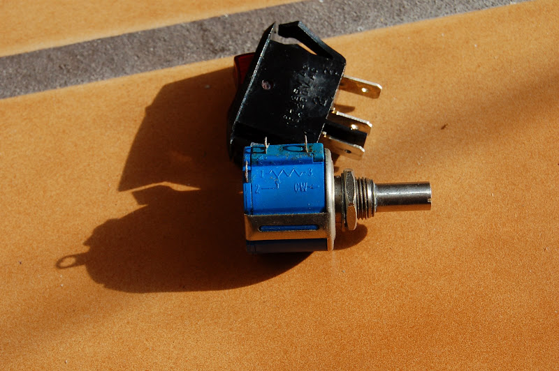
The couple of websites I've been looking at make it sound like 1 is always ground, 2 is always output, and 3 is always input... but the diagram on this pot just muddies the water to me... Assuming I can properly identify the pot leads, is this a correct diagram for what I'm trying to do? Or do I even need to run a ground from the ground spade on the pot? |
|
Quoted:
no ground needed, run power to 1, and a wire to the light from 2, and ground the other side of the light Thanks, that's exactly right. It's wired up now, but I need to make a plate to mount the pot and switch to and then bolt that somewhere in the cab. I'll post pics when it's all done. |
|
If you use that the way it was described above, your potetiometer is going to carry the full current going to your LED lights. Most pots aren't rated for that kind of current conduction. What is the current/power rating of that pot?
For example, with 24V input and the lights on full, teh pot will have a 12V drop across the terminal and wiper. With 1A current (12W LED), your pot will be dissipating 12W and is going to get HOT!, then the plastic case melts, then you get a short circuit when the 24V hits structure ground, then you get sparks and your battery welds the short to ground because you forget to put a fuse in the circuit. Then the gas tank explodes The Earth's atmosphere catches fire and the sky literally falls and all life on Earth ends. :-) |
|
Quoted:
If you use that the way it was described above, your potetiometer is going to carry the full current going to your LED lights. Most pots aren't rated for that kind of current conduction. What is the current/power rating of that pot? For example, with 24V input and the lights on full, teh pot will have a 12V drop across the terminal and wiper. With 1A current (12W LED), your pot will be dissipating 12W and is going to get HOT!, then the plastic case melts, then you get a short circuit when the 24V hits structure ground, then you get sparks and your battery welds the short to ground because you forget to put a fuse in the circuit. Then the gas tank explodes The Earth's atmosphere catches fire and the sky literally falls and all life on Earth ends. :-) Add to that the power is being dissipated in only a small portion of the strip at brighter settings. |
|
Quoted: Quoted: If you use that the way it was described above, your potetiometer is going to carry the full current going to your LED lights. Most pots aren't rated for that kind of current conduction. What is the current/power rating of that pot? For example, with 24V input and the lights on full, teh pot will have a 12V drop across the terminal and wiper. With 1A current (12W LED), your pot will be dissipating 12W and is going to get HOT!, then the plastic case melts, then you get a short circuit when the 24V hits structure ground, then you get sparks and your battery welds the short to ground because you forget to put a fuse in the circuit. Then the gas tank explodes The Earth's atmosphere catches fire and the sky literally falls and all life on Earth ends. :-) Add to that the power is being dissipated in only a small portion of the strip at brighter settings. +1 to all of the above. I was just about to post this. -Foxxz |
|
LOL!
You can get high power dissipation potentiometers but they are usually made with a ceramic body. Even so, they tend to be relatively big and bulky,... and run HOT! Be careful what they are near, be sure to use wire with high temp insulation and fuse them properly. Remember, be careful because we want life on Earth to survive. :-) |
|
Hard to believe that you cannot find a simple PWM to not waste all the power in a resistor.
They run a lot cooler since they turn the power on and off faster than the filament can cool rather than just burning the power to heat. I could build an entire circuit smaller than that potentiometer that would do the job just fine. |
|
Quoted:
Quoted:
an entire circuit 555 timer, a cap, two resistors, and a transistor with sufficient Ifwd to pass the LED current. ar-jedi Needs a pot if it is going to be adjustable. Some voltage protection is also going to be needed. Car electrical systems are NOT a friendly place. |
|
Thanks, but the max current draw is only 83mA. Not sure what the current rating for the pot is, but I'm sure it can handle that.
As far as wiring them in series, that's what this thing is. It's a series of like 18 or 21 (or some multiple of 3) LEDs in a strip. The instructions say you can remove LEDs from the strip, but only in groups of 3. So it sounds to me like it's in parallel series of 3 LEDs in each series. It's supposedly "for experimental aircraft only." So I'm sure it can handle typical "12V" variable voltage. I've measured each deuce battery with the generator turning at 2000 rpm and each batt reads between 13.5 and 13.8 With the generator at rest, the batts read like 12.8V or so apiece. And I did run the strip that way. At any rate, I wired a 5 amp fuse inline right up close to the battery, so you probably won't read about the burned to death dumbass on the 6 o'clock news. |
|
Quoted:
Hard to believe that you cannot find a simple PWM to not waste all the power in a resistor. They run a lot cooler since they turn the power on and off faster than the filament can cool rather than just burning the power to heat. I could build an entire circuit smaller than that potentiometer that would do the job just fine. I'd love to go with PWM, but I don't know enough about it to build a PWM controller. And the pot was like $2. But if you want to edumucate me, I'm all ears. For example, I'd love to investigate PWM as a means of controlling router spindle speed on my CNC router. It's a Bosch 2.25hp variable speed wood router. Do you think it can be PWM controlled? |
|
Quoted:
Thanks, but the max current draw is only 83mA. Not sure what the current rating for the pot is, but I'm sure it can handle that. the pot will need to dissipate 1W when dropping 12V. V= I * R; 12 = 0.083*R; R= 12/0.083 = ~144ohms. P=I^2 * R = (0.083^2)*144 = ~1W Quoted:
you probably won't read about the burned to death dumbass on the 6 o'clock news. you should just power the LEDs from one battery and drop a couple of volts using several diodes. this is the simplest solution. ar-jedi |
|
Quoted:
It's a Bosch 2.25hp variable speed wood router. Do you think it can be PWM controlled? well it already has a PWM controller on it (if it's like my 1613EVS). take the module apart, take some measurements, and use an external digital pot (digipot). otherwise, you can buy a programmable external PWM controller, and set the router's dial to maximum speed. i think using the router's electronics will net you better results. ar-jedi |
|
Quoted:
Quoted:
Thanks, but the max current draw is only 83mA. Not sure what the current rating for the pot is, but I'm sure it can handle that. the pot will need to dissipate 1W when dropping 12V. V= I * R; 12 = 0.083*R; R= 12/0.083 = ~144ohms. P=I^2 * R = (0.083^2)*144 = ~1W Quoted:
you probably won't read about the burned to death dumbass on the 6 o'clock news. you should just power the LEDs from one battery. this is the simplest solution. ar-jedi That's what I did. The vehicle's battery is two giant 12V military batts in series. I'm just tapping off one of the 12V batteries. Here's the diagram of how I actually ended up wiring it. 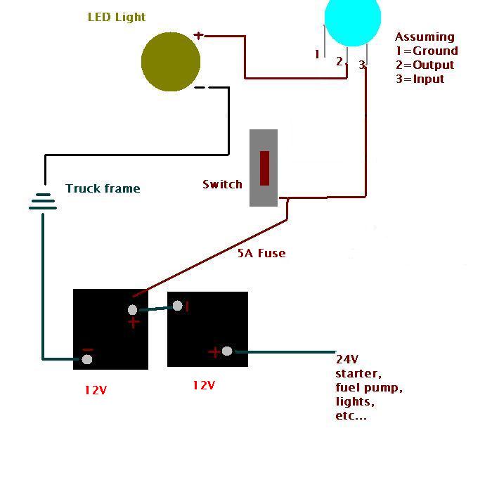
Yeah, I guess I'll keep an eye on it. Thanks for the heads up on the power dissipation thing. The instruction sheet said to use any 5k ohm pot which is what I got, but I'll be sure to feel it to make sure it isn't heating up to much over time. |
|
Quoted:
Quoted:
It's a Bosch 2.25hp variable speed wood router. Do you think it can be PWM controlled? well it already has a PWM controller on it (if it's like my 1613EVS). take the module apart, take some measurements, and use an external digital pot (digipot). otherwise, you can buy a programmable external PWM controller, and set the router's dial to maximum speed. i think using the router's electronics will net you better results. ar-jedi I want to be able to control the router speed from my cnc controller software. So I can set spindle speed in gcode. Will that external PWM controller have pinouts that I can run to the CNC breakout board? |
|
Quoted:
Quoted:
Hard to believe that you cannot find a simple PWM to not waste all the power in a resistor. They run a lot cooler since they turn the power on and off faster than the filament can cool rather than just burning the power to heat. I could build an entire circuit smaller than that potentiometer that would do the job just fine. I'd love to go with PWM, but I don't know enough about it to build a PWM controller. And the pot was like $2. But if you want to edumucate me, I'm all ears. For example, I'd love to investigate PWM as a means of controlling router spindle speed on my CNC router. It's a Bosch 2.25hp variable speed wood router. Do you think it can be PWM controlled? You can buy a router speed control good for 3 amp routers for about $25. PWM is not good for motors universal motors not designed for it. |