


Posted: 12/13/2018 7:56:05 PM EDT
|
After posting in a couple of the DCS threads running right now, I thought I would open a thread that relates to hardware modding.
Having a 3D printer (Ender 3) has been a great tool to make parts for some of my mods. So to kick it off... How about a mod to mount a Thrustmaster MFD to a 8" Neewer monitor. This also uses the Thrustmaster base as I found it to be heavy enough to not move and solid enough to support everything. You will need for each MFD 4ea M4x8 screws for the VESA mount in the back of the monitor. 8ea M3x10 (or x12) 6ea M3 nuts Cougar MFD Mount Installation is pretty straight forward. Print the following parts: 1 X MFD Monitor Ver2 1 X MFD Monitor Ver2 Insert 1 X MFD VESA Plate Base 1 X MFD VESA Plate Optional: Standard Mounting 2 X VESA Arm Med 2 X VESA Arm Short (connects to MFD Base to MFD lower frame screw holes) Taller Mounting 2 X VESA Arm Long 2 X VESA Arm Med (connects to MFD Base to MFD lower frame screw holes) I printed in grey to simulate the interior of the planes a little more... But I may do a set in black as well. Hell, I have a bunch of Carbon Fiber Vinyl wrap I may just put on them! Enjoy! Oh and ignore the screwed up top of the MFD base in the pics... Im trying to diagnose a printer setting for layer thickness. 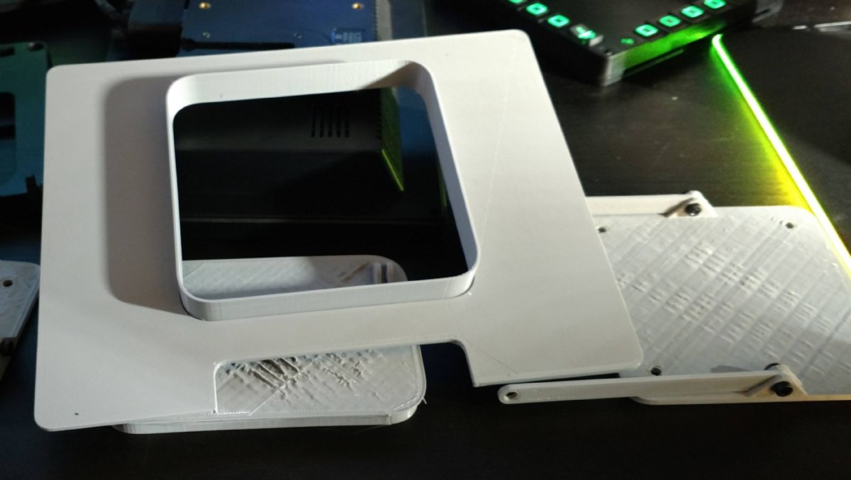


|

|
Quoted:
what inputs are you using on those monitors? I am assuming you have your other two monitors down due to have the extra three for the MFD's? |
|
Quoted:
You can do it a bunch of ways, a lot of people just use usb-vga for the mfds. No need to turn off other monitors, they don't need to run off the main video card. Quoted:
Quoted:
what inputs are you using on those monitors? I am assuming you have your other two monitors down due to have the extra three for the MFD's? EXACTLY! I am running a VGA-USB adapter to each display panel. Works perfectly with the Neewer monitors. You may have to adjust the monitors refresh rate but that is an easy setting change. |
Working on some new things... 
So... how should I share the parts for some of the other things Ive been trying out? Most are done in TinkerCad or in 3DS Max, but converted back and forth via .OBJ files, exported out to .STL and cut up in Cura. I guess I could post them onto Thingverse, but kinda holding on to them for the peeps here for now. Doesnt really matter I guess. Updated the front MFD Mount arm to be stronger and offset to fit the base and the MFD better without them looking bent because, well, they were bent.  I'll add a pic once I have them mounted. I'll add a pic once I have them mounted.

Next PROJECT is to build a FUNCTIONAL Hornet APC module!!! I have a little cleanup on some of the parts, but nothing I didnt expect. I may print some parts at a little higher resolution, but still pondering that. I did not created the below parts. There is a thread over on ED forums that goes through the entire life of the APC build with details on switches, knows, led's, etc. The guy who did this really did a fantastic job on the parts and layout. Spectacular. I may look at putting in an LED touchscreen in the center instead of a touch pad, buttons and led's. Just a thought on a different version. 
The print actually looks a lot better than the pic shows. Lettering is there for the infill. Plan is to sand it down smooth to take out any of the imperfections, paint it matte black then infill the lettering with fluoro white paint. 
This is printed in 4 different parts. 
|
|
Pics of the front MFD mount update.
The file has been updated in the link in the first post. There are two of them. I used the Front MFD Arm 60 and the medium arm for the back vesa arms. 
Updated arms are on the Left side MFD that connects the MFD base to the MFD panel. Those were mating parts, so I did an offset arm. The whole assembly is much tighter now. Nothing moves and it pretty much sets itself all into place. Rock solid! 
|
|
So thingverse has a post that has a few different Warthog stick extensions. One of them is a curved model.
Printed that one out... Very nice. Ordered a PS/2 extension cable, cut it down to fit the extension, resoldered the wires, modified the ends per the instructions on the web (remove a pin and the middle post block on one end, enlarge the hold on the other end). Dremeled out the lower connector hole on the extension, dremeled off the plastic around the connectors to a smooth cylinder that fit thru the lower hole and VOILA! I do plan on printing this out in PETG in the next day or so for the added strength, but running it as a test tonight, holy cow! Talk about better control of the aircraft. MUCH better!!! Nice thing is... It prints as 1 piece as the locking nut is printed at the same time. Slight twist to break it free and boom! Warthog Extension Not my files.   
|
|
Quoted:
Working on some new things...
So... how should I share the parts for some of the other things Ive been trying out? Most are done in TinkerCad or in 3DS Max, but converted back and forth via .OBJ files, exported out to .STL and cut up in Cura. I guess I could post them onto Thingverse, but kinda holding on to them for the peeps here for now. Doesnt really matter I guess. Updated the front MFD Mount arm to be stronger and offset to fit the base and the MFD better without them looking bent because, well, they were bent. I'll add a pic once I have them mounted.
https://www.AR15.Com/media/mediaFiles/112200/Capture_JPG-783198.jpg Next PROJECT is to build a FUNCTIONAL Hornet APC module!!! I have a little cleanup on some of the parts, but nothing I didnt expect. I may print some parts at a little higher resolution, but still pondering that. I did not created the below parts. There is a thread over on ED forums that goes through the entire life of the APC build with details on switches, knows, led's, etc. The guy who did this really did a fantastic job on the parts and layout. Spectacular. I may look at putting in an LED touchscreen in the center instead of a touch pad, buttons and led's. Just a thought on a different version. https://www.AR15.Com/media/mediaFiles/112200/IMG_20181223_191335300-783200.jpg The print actually looks a lot better than the pic shows. Lettering is there for the infill. Plan is to sand it down smooth to take out any of the imperfections, paint it matte black then infill the lettering with fluoro white paint. https://www.AR15.Com/media/mediaFiles/112200/IMG_20181223_191325272-783202.jpg This is printed in 4 different parts. https://www.AR15.Com/media/mediaFiles/112200/IMG_20181223_170420902-783205.jpg |
|
Quoted: You could make those the same way they do aircraft panels. Make the panel from clear plastic and use LED's to light the clear plastic then either silkscreen your labels (as a negative) or make a plastic cover for it. That way the lettering lights up. |
|
Quoted:
Tried this extension for the second time. The extension broke right above the nut when I broke it free. 
Probably going to go the PVC route next time. The info page says to print at .1 resolution. So extra fine. Im going to print one out in PETG tonight or tomorrow just to get the extra strength, but the one in my pictures is from PLA and had no issue breaking the nut free. |
|
Quoted:
We have an ID plate engraver at work. Haven't learned how to use it yet, but as soon as I find a source for black on clear plastic sheeting, I'll probably make a button box and use it to make a cover for it. |
|
Quoted:
What resolution did you print it at? The info page says to print at .1 resolution. So extra fine. Im going to print one out in PETG tonight or tomorrow just to get the extra strength, but the one in my pictures is from PLA and had no issue breaking the nut free. ETA: even with losing power half way through, I resumed the print and the collet was barely attached to the extension. A little trimming and it for perfectly! |
|
Quoted:
I sliced it again at .1 and it looks like the print time is longer, so I'll try again. ETA: even with losing power half way through, I resumed the print and the collet was barely attached to the extension. A little trimming and it for perfectly! I printed a straight extension at .2 and there was no way in hell that thing as going break loose!
Just loaded up the PETG to print out a mount for my chair that i designed. Hoping it works. So I plan on printing off a couple of the extensions just to have the added strength of the PETG material. |
|
Quoted:
AWESOME! I think it has to be printed at .1 in order for the parts to have just enough separation or thin enough connection to be able to break free. I printed a straight extension at .2 and there was no way in hell that thing as going break loose!
Just loaded up the PETG to print out a mount for my chair that i designed. Hoping it works. So I plan on printing off a couple of the extensions just to have the added strength of the PETG material. For those looking, the extension is here: Warthog Extensions That is not my work at all and I take no credit for the original creators work on this.  
|
Join the Community
Your next conversation starts here.
Create your free account to join discussions, share your experience, save topics, and connect with the AR15.COM community.
- Join discussions
- Follow topics and replies
- Connect with fellow enthusiasts
Already a member? Sign in
Stay informed by subscribing to our Newsletter