


Finally made my truck NVIS antenna. ( 2 month update ) (Page 1 of 2)

Posted: 8/28/2025 1:39:35 PM EDT
[Last Edit: Mach][Edited]
|
Thought I would share. i have been wanting to make a permanent Near vertical takeoff angle antenna for mobile for 80/60/40 meters for over a year. I finally set out to do it a couple days ago. It seems to work very well. I tune it from the cab with a PWM speed controller with forward and reverse and variable speed and geared low rpm DC motor that belt drives a high voltage air variable capacitor. Here were some of the design requirements: I wanted it to work on 80/60/40 meters for regional comm, ground wave and NVIS not DX. I wanted to easily tune it while driving. i wanted it out of the way so I could still use the truck to haul shit. It needed to be small enough to fit on or in the 8 foot bed tundra. It needed to be usable at highway speeds. I wanted to minimize the RF in the cab for people and the computers. It needed to be cheap. I bought an air variable cap with at least 7k volts capacity at NearFest for $15 I got the aluminum 3/8 inch tubing for free. I used a piece of scrap wood to mount the cap on. I bought the PWM controller, motor, and pullies and belt for less than $40 on amazon. I designed the cap location which is the highest voltage point on the loop to be closest to the seats because the highest current point which is also the highest RF radiation point is at the opposite location of the highest voltage point. So I put the cap closest to the cab on the bottom of the loop which put the highest radiation point at the back of the truck up high against the ceiling. I bent and molded the tubing up against the bed and the fiberglass cap out of the way. I made the drive loop out of 3/8 inch copper tubing and oriented 90 degrees out of the plane of the main loop so that it would not hang down and not be in the way. It is flush with the ceiling. The drive loop does not need to be in plane to couple to the main loop. The loop by itself tunes in the 40m band to between 50 and 52 ohms at an SWR of 1.0 to 1. 60m band is a little higher, and 80m a little higher than that but I also tune the output from the finals using an MFJ-993 auto tuner with the IC-7300. It actually works with just the internal IC-7300 tuner, but i use the MFJ tuner in line with my base loaded vertical that tunes 80-6 meters, so I kept that configuration to make it simple and just in case high voltage gets to the radio side of the coax, It would burn up the MFJ and not the IC-7300. But so far that is not an issue. I tune it with the PWM motor speed controller and just listen for the increase in noise, look at the waterfall noise bandwidth and put that noise bandwdth so the freq is in the middle and then hit tune to fine tune it in case I am off a little. It works wonderfully. From SE MA I have made daytime QSOs first while sitting in the driveway to get down the tuning and then on the roll. I have made QSOs on this antenna in MA, NY, NJ, NH, and VT with signal reports from 55 to 59 in the middle of the day the last 2 days when conditions were not great. People running amps have been up to 20 over 9 on reception and I put a whole 100 watts into this antenna. capacitor voltage estimated to be about 3000 volts or so. Based on calculators, the antenna on 40m is about 54% efficient, 60m is less, and 80m is about 10%, which is all very much more than a short base load vertical AND have the Near Vertical takeoff ( instead of a near vertical null ) that I desired. I estimate this mag loop, based on S meter comparisons between antennas, to be about 36 dB better than the vertical on the truck even though I know the S meter low end of the IC-7300 is set to show artificially low. I am going to cover the antenna with material and velcro ( it sticks to the inside of the material covering of the fiberglass ) and make a box for the cap and motor to protect it and make it less visible from outside. Pics: 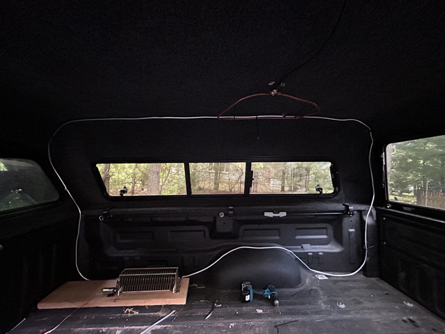 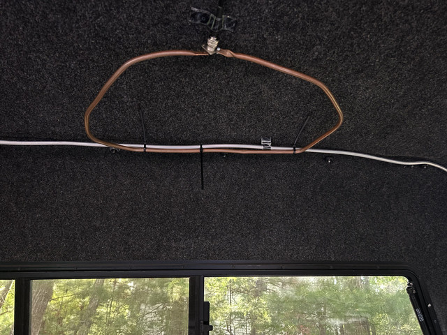 |









|
I was thinking pleasant thoughts about this design... then remembered that my Suburban doesn't have a fiberglass top like the cap on OPs truck. : - / ... so maybe I need a pickup too... 
|
Disclaimer - OP is bad at knowing things, and might catch on fire.
Vet - Op MMAMA
Every other species kills off their stupid......we cater to them. -- spin-drift
Nobody ever called 911&said I just did something smart. -- TheFlynDutchman
Vet - Op MMAMA
Every other species kills off their stupid......we cater to them. -- spin-drift
Nobody ever called 911&said I just did something smart. -- TheFlynDutchman
|
Originally Posted By lorazepam: Mag loops are awesome, and I will build one someday. What is the value of the capacitor? It tunes from 3.5 to 7.5 Mhz. |
|
So I was having a nice 40 meter 55 QSO both ways from the truck with a PA station 280 miles away and then someone turned off the propagation switch and the signals dropped to S0 both directions, we could still make out just enough to know we both had the bottom fall out. Another indication this was a NVIS QSO, but I failed to lookup what the FoF2 and LUF were. One of these days I will pull over, stop the truck and look it up to confirm it was probably NVIS, but all indications so far is that this mobile and hidden antenna is indeed NVIS capable in the real world. One of the things I did do during this QSO was travel in a complete circle while receiving and while transmitting to see if there was any in increase or decrease in signal reception on either end since a mag loop is directional in the plane of the loop for non-near vertical takeoff angles and I saw no variation at all and was told my signal was a steady 55 which indicated the QSO was probably from a near vertical angle of incidence off the antenna. I have not been this excited ( or any excited ) about anything in ham radio for a long time. Not since I acquired and set up my ANAN-7000 radio. Spending the time building this antenna and getting it to work was a great idea. @TNC Over 5 years ago we talked about how to set up regional comm with ham radio from a mobile for a friend of yours traveling in hilly terrain with no cell service. I think I finally did it. ( although an inReach device would be a lot easier ) |

|
Originally Posted By Mach: So I was having a nice 40 meter 55 QSO both ways from the truck with a PA station 280 miles away and then someone turned off the propagation switch and the signals dropped to S0 both directions, we could still make out just enough to know we both had the bottom fall out. Another indication this was a NVIS QSO, but I failed to lookup what the FoF2 and LUF were. One of these days I will pull over, stop the truck and look it up to confirm it was probably NVIS, but all indications so far is that this mobile and hidden antenna is indeed NVIS capable in the real world. One of the things I did do during this QSO was travel in a complete circle while receiving and while transmitting to see if there was any in increase or decrease in signal reception on either end since a mag loop is directional in the plane of the loop for non-near vertical takeoff angles and I saw no variation at all and was told my signal was a steady 55 which indicated the QSO was probably from a near vertical angle of incidence off the antenna. I have not been this excited ( or any excited ) about anything in ham radio for a long time. Not since I acquired and set up my ANAN-7000 radio. Spending the time building this antenna and getting it to work was a great idea. @TNC Over 5 years ago we talked about how to set up regional comm with ham radio from a mobile for a friend of yours traveling in hilly terrain with no cell service. I think I finally did it. ( although an inReach device would be a lot easier ) I had bookmarked this a while back as it's even more relevant to my interests today. A friend of mine lives nearby but out of LOS range, and we've been scheming how to establish comms |
I know I'll never go home.
So set fire to your ships, and past regrets, and be free.
So set fire to your ships, and past regrets, and be free.
|
Originally Posted By TNC: I had bookmarked this a while back as it's even more relevant to my interests today. A friend of mine lives nearby but out of LOS range, and we've been scheming how to establish comms How far way are you from him. If he is a ham, it's a no brainer. Having 40/60 and 80 as options is the way to go. |
|
He's in the worst spot. About 20 miles away with around a ridge around 1000' above LOS between us. We can both hit the local mountaintop repeater, but of course we're looking to divorce ourselves from any infrastructure. |
I know I'll never go home.
So set fire to your ships, and past regrets, and be free.
So set fire to your ships, and past regrets, and be free.
|
Originally Posted By TNC: He's in the worst spot. About 20 miles away with around a ridge around 1000' above LOS between us. We can both hit the local mountaintop repeater, but of course we're looking to divorce ourselves from any infrastructure. If possible you could try putting up a UHF yagi connected to a UHF ( UHF because it is small and when painted would be hard to see from any distance ) yagi via short coax, enough to point each yagi at the QTH and it will act like a passive repeater. If you could both do 900 mhz the yagis would be even smaller. You could investigate 10 Ghz dishes if you had something down ridge laterally like a water tower or even a hill that you can both see from your QTH and you could each set the dish to bounce 10 gig off of the thing you can each see. People get comm long distances doing that. The advantage to that and the double yagis is they are hard to intercept because position matters. You could also think about a simplex repeater that is battery operated and solar charged if you could discreetly put it someplace you could both hit. that is infrastructure and cheap but it would be your infrastructure and cost less than about $100. It would be the size of a waterproof 1/2 556 ammo can and a wire up a tree with a small solar panel to charge the battery in the Baofang which now come with usb connection for charging right to the battery. The tiny simplex repeater ( in have one ) is powered by USB and is the size of a deck of cards. I have one of these . But he now sells a complete waterproof solutions, just add the UV5R Or the NVIS way but that will not be a sure thing, conditions would have to be favorable to get comm. |

|
Originally Posted By TNC: He's in the worst spot. About 20 miles away with around a ridge around 1000' above LOS between us. We can both hit the local mountaintop repeater, but of course we're looking to divorce ourselves from any infrastructure. Try 40/80 M with wire antennas of your choice. They should be at 15' - 30' above ground. Another ARFcomer and I live about 45 miles apart, with two significant ridges in between. On 40 M we can talk fine, with EFHWs 22' (mine) and 45'-25', sloping (his). He initially laid his antenna out 8' above the ground and it was not nearly as good, apparently too much ground loss. OP: That is a great solution and seems to work great! |
|
Originally Posted By Prolix: Is there insulation between the copper feed loop and the aluminum radiating loop, or does it function more as a gamma match at the points where the copper shorts to the aluminum loop due to the zip ties? There are many ways to feed the loop, I think this is still considered a feed loop, not a gamma match because it is a loop, even though it is in direct contact with the main loop. There is variation of the drive / feed loop that is a loop that uses a section of the main loop. I made a loop like that once and it worked fine. |
|
Originally Posted By TVille: Try 40/80 M with wire antennas of your choice. They should be at 15' - 30' above ground. Another ARFcomer and I live about 45 miles apart, with two significant ridges in between. On 40 M we can talk fine, with EFHWs 22' (mine) and 45'-25', sloping (his). He initially laid his antenna out 8' above the ground and it was not nearly as good, apparently too much ground loss. OP: That is a great solution and seems to work great! Originally Posted By TVille: Originally Posted By TNC: He's in the worst spot. About 20 miles away with around a ridge around 1000' above LOS between us. We can both hit the local mountaintop repeater, but of course we're looking to divorce ourselves from any infrastructure. Try 40/80 M with wire antennas of your choice. They should be at 15' - 30' above ground. Another ARFcomer and I live about 45 miles apart, with two significant ridges in between. On 40 M we can talk fine, with EFHWs 22' (mine) and 45'-25', sloping (his). He initially laid his antenna out 8' above the ground and it was not nearly as good, apparently too much ground loss. OP: That is a great solution and seems to work great! |
|
I have found while driving, that tuning the loop to another band is tedious. I am now working on a completely analog sensor and display to approximate what frequency the loop is tuned to without transmitting to make changing bands much easier with less attention. I hope to have it done by tomorrow, if the concept actually works. The parts should arrive today. I have never seen it done anywhere, it's a unique idea, so it may have a major pitfall I have not thought of. |

|
Tagged to follow. Since I made the other thread about the Enigma transmission, reminded me about the NVIS cage antenna that was above the German vehicles transmitting Enigma coded messages. Attached File |
|
So I had this idea to attach a linear taper potentiometer to the air variable capacitor to the axle of the capacitor and use a pot above the main pot and a pot below the main pot and use a voltage divider to calibrate the voltage reading of the divider to the position of the air variable capacitor. I thought the whole thing would be linear. The voltage readout at 3.5 Mhz is 3.5 volts. The voltage readout at 7.2 Mhz is 7.2 volts, and is perfectly repeatable through the 180 degrees of the capacitor. I assumed between the points would be linear, but it is not. At 3.9 mhz the voltage reads 4.1, at 5.3 mhz the voltage reads 6.3. It is not linear. The frequency that the loop is tuned to raises slower than the rotary position of the capacitor. Something is not linear. I am pretty sure the linear taper pot is linear using DC. I am pretty sure the voltage divider is linear as the voltage changes. I assumed the capacitance value changes linearly with the area of overlap of the plates but maybe it doesn't. After all when completely unmeshed, their is no overlap but there is still a capacitance. But when almost fully meshed, it is not linear. at 3.6 Mhz, the voltage reads 3.6, almost fully meshed at 3.9 mhz, is slightly less fully meshed and the voltage reads 4.1 instead of 3.9, so in only 0.3 mhz increase in freq, the voltage divider is already off 0.2 volts. I thought capacitance varying with frequency was linear, but maybe not. I though inductance varying with frequency was also linear, the loop is an inductor, but again maybe not. I suspect the non-linear effect is from the tuned frequency coupling differently with the surrounding metal of the truck.. But I am just guessing. Anybody have any ideas why the tuned frequency is not linear to the movement of the variable capacitor |

| I know with an air cap there is some capacitance of the plates before they are meshed. I’ve measured that, although it’s been a long time ago. I’ve read that the charge distribution isn’t completely uniform either (I think more toward the edges). That might be messing with the numbers if you can’t get a good linear approx accounting for the fixed offset of the unmeshed plates. |

|
Ok thanks. I guess I will have to settle for having a chart with what voltages correspond to what bands and what channels in the 60 meter band. It will be better than what I have now ( which is nothing ) and will tell me at least when I am in the band. I was hoping for pretty close frequency / voltage match, but I don't see a way to make that happen without moving to digital with a rotational angle sensor and a microprocessor. Never done anything like that and I would not know what I was doing. I could probably have 3 different voltage dividers calibrated for each band at the edges with either switches to switch the band or 3 separate displays one for each band, but I was trying to keep this very simple. maybe I would be better off with a camera and some markings on the cap. |
|
Seems like I’ve read about someone using a noise generator to tune one of those up remotely. I was just thinking that might work really well with a waterfall display. Have you noticed if turning the truck ever changes the reception? I’m not too smart on mag loops but seems like some of them can have some nulls that people exploit for DF and such. |
|
Originally Posted By BASE: Seems like I've read about someone using a noise generator to tune one of those up remotely. I was just thinking that might work really well with a waterfall display. Have you noticed if turning the truck ever changes the reception? I'm not too smart on mag loops but seems like some of them can have some nulls that people exploit for DF and such. That does work well, increase noise once in the band. For single band it works very well. However between bands, I have no idea where the coil is. The noise on the waterfall works when there is noise. On the highway or country roads, there is not enough noise to see any. |
|
Originally Posted By lorazepam: Tuning the mag loop, turn the capacitor until the noise level is at it's highest. That should have you tuned up. |
|
Plates on air variable caps in the days of antiquity were mounted eccentrically to give a more linear band spread on the dial. You may need to do the same thing with your loop tuning capacitance, despite the pains you have taken to get your potentiometer voltage divider to be linear. An example:https://www.ebay.com/itm/388745173969?_trkparms=amclksrc%3DITM%26aid%3D1110006%26algo%3DHOMESPLICE.SIM%26ao%3D1%26asc%3D291555%26meid%3D320c302e833c4909945acf9d4c193345%26pid%3D101875%26rk%3D4%26rkt%3D4%26sd%3D388744544010%26itm%3D388745173969%26pmt%3D1%26noa%3D0%26pg%3D2332490%26algv%3DSimVIDwebV3WithCPCExpansionEmbeddingSearchQuerySemanticBroadMatchSingularityRecallReplaceKnnV4WithVectorDbNsOptHotPlRecallCIICentroidCoviewCPCAuto&_trksid=p2332490.c101875.m1851&itmprp=cksum%3A388745173969320c302e833c4909945acf9d4c193345%7Cenc%3AAQAKAAABcG96wQ16jds4VFcrhy1F3d4mbwZUJI9Fs%252BgdXYAHIzlX2e3YaNh7x%252BEnKA3G%252BCqSl1Xn4McfcWFK1GytmS2qxJ87mtE8Gm3iR1Ja4WBwh0hNHJrJx3Ki5mp04ow4CO7lP%252BooCybZDDU%252BbbSwmg7CbTin%252BBzBzbCYVnbjvyQAHu6--HI4MB7SvJl5IJqlyvomgoLMlgT6qAJzX0SANJhty2eKjMIJ5MaGy8rvgugwNUjjK3OD3iV4Pou%252FVg%252Fszr%252F794Dv4BkD57GOl8qrLKZCHXx1d876HPB33wsHcoONtDZdxu%252BXXVhZt8qthNNwmvK3QorqG6Mk6%252B1EYaFZ1D4qZR26DvXRn4bOtsidBtjy6c5kjDPsjSAdXv2WlZrdOC4uNNoffsYzsidbZoRCkmpLy0EwIIa3TCzmi0Wi6DtxW8jp6zmeeiE6Xr46msxAxq%252BdV94YjPh8EVuDElnAohqe7H6NHzAehvu3HOHl0yNWkjCg%7Campid%3APL_CLK%7Cclp%3A2332490&itmmeta=01K46MWFM286C4JCDSHHH0KW3R |
|
Originally Posted By Prolix: Plates on air variable caps in the days of antiquity were mounted eccentrically to give a more linear band spread on the dial. You may need to do the same thing with your loop tuning capacitance, despite the pains you have taken to get your potentiometer voltage divider to be linear. An example:https://www.ebay.com/itm/388745173969?_trkparms=amclksrc%3DITM%26aid%3D1110006%26algo%3DHOMESPLICE.SIM%26ao%3D1%26asc%3D291555%26meid%3D320c302e833c4909945acf9d4c193345%26pid%3D101875%26rk%3D4%26rkt%3D4%26sd%3D388744544010%26itm%3D388745173969%26pmt%3D1%26noa%3D0%26pg%3D2332490%26algv%3DSimVIDwebV3WithCPCExpansionEmbeddingSearchQuerySemanticBroadMatchSingularityRecallReplaceKnnV4WithVectorDbNsOptHotPlRecallCIICentroidCoviewCPCAuto&_trksid=p2332490.c101875.m1851&itmprp=cksum%3A388745173969320c302e833c4909945acf9d4c193345%7Cenc%3AAQAKAAABcG96wQ16jds4VFcrhy1F3d4mbwZUJI9Fs%252BgdXYAHIzlX2e3YaNh7x%252BEnKA3G%252BCqSl1Xn4McfcWFK1GytmS2qxJ87mtE8Gm3iR1Ja4WBwh0hNHJrJx3Ki5mp04ow4CO7lP%252BooCybZDDU%252BbbSwmg7CbTin%252BBzBzbCYVnbjvyQAHu6--HI4MB7SvJl5IJqlyvomgoLMlgT6qAJzX0SANJhty2eKjMIJ5MaGy8rvgugwNUjjK3OD3iV4Pou%252FVg%252Fszr%252F794Dv4BkD57GOl8qrLKZCHXx1d876HPB33wsHcoONtDZdxu%252BXXVhZt8qthNNwmvK3QorqG6Mk6%252B1EYaFZ1D4qZR26DvXRn4bOtsidBtjy6c5kjDPsjSAdXv2WlZrdOC4uNNoffsYzsidbZoRCkmpLy0EwIIa3TCzmi0Wi6DtxW8jp6zmeeiE6Xr46msxAxq%252BdV94YjPh8EVuDElnAohqe7H6NHzAehvu3HOHl0yNWkjCg%7Campid%3APL_CLK%7Cclp%3A2332490&itmmeta=01K46MWFM286C4JCDSHHH0KW3R It is never going to be truly linear, it can be better approximated by changing the end shapes of the plates as the start to mesh / end meshing. As was pointed out above, there is minimum capacitance even when completely un-meshed and that makes the non-linear behavior between dial position and frequency response especially at the ends non-linear. I think a way to null this out is to use a very large capacitor with a very wide range and just use the capacitor in the middle of the range. Or, I suspect a vacuum variable will be more much more linear just from looking at the plates. I do have a 15kV 20 -1000 pf vacuum variable, but then I have to build limit switches to stop the motor so the motor doesn't destroy the capacitor at the ends. Or forget about the other bands and put another cap in series so that the smaller values I need for the 40 meter band are located at a further meshed point on the this capacitor away from the un-meshed end. I have some thinkin to do. |
|
Glad to contribute meaningfully. Your project sounds fun. Did a 24" diameter mag loop two decades ago, would like to play again now that I'm retired. That Marconi Institute article seems to hit all the points with all the corresponding math. The early experimenters sure had to have some manual skills with a metal file, as well as knowing how to run a slide rule. We (modern ham homebuilders) stand of the shoulders of giants. |
|
I was able to use the post above recognizing that each end of the plate makes the capacitance non-linear, so I used that info and moved to the calibrated points at 3.9 high end of the 80m band instead of 3.6 and the low end of the 40m band instead of closer to 7.3 and it did help some. My biggest issue was while play radio while driving I would get distracted by driving, :) , and lose track of where the capacitor was moving and not know where the loop was tuned to at the moment. So I moved the reference points from the fully meshed at 3.5 to 3.9 further away from the ends of the cap influence being non-linear and did the same with the 40 m band reference point. I originally chose close to the end of the cap so I would know where the end was. But instead I will settle for entering the band and I was able to get 3.9 and 7.1 and for the center channel of 60 meters the voltage is now 6.0 which I can remember. I can live with that. it will be a help to just know what band the loop is currently in since I can't just keep an eye on it while driving, so if i overshoot it while distracted by driving, I can get back to a known reference point easily. I will live with this until I decide to go digital with a stepper motor, an arduino, and a dial to dial in the freq I want it to stop at. It may take a while or it may be never. Sometimes you just have to settle, which is what i am doing right now. I am happy I have a working mobile NIVIS on 40, 60, and 80m. I have been using 40m a lot, I have listened to QSOs on 60 and 80 but have not tried to make a QSO yet. Been spending most of my time trying to get a display i can use to know what band the loop in on. Now I have a power problem. at 100 watts the radio intermittently shuts off as the voltage drops during transmit. I think it might be an poor power pole connection, so i have to track that down. |
| It would be kinda ghetto, but you could run a diplexer on the coax, up to a NanoVNA mounted up there somewhere. With an sd card in it, you can save your presets for the band sweep. I wouldnt be staring at that while driving, but could give good data while stopped. |
|
By now you're probably familiar with the mag loop pedestrian mobile literature, and copper pipe trombone capacitors, tuned remotely with a pair of syringes and tubing, using hydraulics. For higher efficiency (every milliohm counts in a small loop) consider a butterfly capacitor with the rotor floating above ground and the stator sections connected to the loop ends - eliminates ohmic losses in the rotor shaft to frame brushes. A double trombone cap from tubing offers the same advantage. |
|
Update: Just made my first 60 meter QSO. Other station was 65 miles away. f0F2 was 9.525 and we were 59 both ways. I switch to the mobile tuned vertical and his signal was nowhere to be seen or heard with noise at S0. Back to the loop and he was a solid 59. Looks like that was indeed an NVIS contact from my truck? Between the near vertical RF pattern of the loop and the much greater efficiency, napkin math shows that to be ( I know IC-7300 S meter is not that accurate on the low end ) but hell, on that meter that is a 54 db difference. Yippy! |
|
Originally Posted By Prolix: By now you're probably familiar with the mag loop pedestrian mobile literature, and copper pipe trombone capacitors, tuned remotely with a pair of syringes and tubing, using hydraulics. For higher efficiency (every milliohm counts in a small loop) consider a butterfly capacitor with the rotor floating above ground and the stator sections connected to the loop ends - eliminates ohmic losses in the rotor shaft to frame brushes. A double trombone cap from tubing offers the same advantage. I am familiar with the pipe in a pipe caps and the tuning. |
|
Originally Posted By WillieTangoFox: It would be kinda ghetto, but you could run a diplexer on the coax, up to a NanoVNA mounted up there somewhere. With an sd card in it, you can save your presets for the band sweep. I wouldnt be staring at that while driving, but could give good data while stopped. |
|
Probably final pics for a while. used a belt to prevent high voltage on the motor.  Other end shaft connected to the pot for voltage readout of shaft position. Shaft is HV insulated. 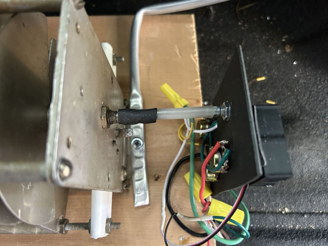 Voltage calibration pots for 2 ends of the cap position with voltage readout so I can do it without my DVM. 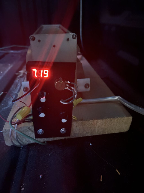 PWM control of motor with voltage readout indicating approximate position of capacitor. Shows me the capacitor is turning, which direction and when it gets to each band and gross approximation of frequency. 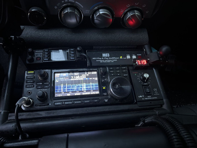 |

|
Originally Posted By Prolix: Replace the current air variable with a butterfly style and you're dialed in! Do everything you can to reduce ohmic losses in that radiating loop. Big fat conductor, soldered connections throughout. https://i.imgur.com/5xgm1Hi.jpeg Yes going to a 4 inch conductor will increase efficiency to close to 100%, having a 3/8 inch conductor is only down 3 db from the 4 inch conductor. That is 1/2 an S point. A 3/8 in conductor is much small and easier to handle and takes up much less room in the bed and is bent against the walls, into the corners, and up against a ceiling keeping it out of the way for using the truck as a truck. Soldering all the connections IMO doesn't really do much. Sure it changes radiation resistance some, but the entire thing is tuned to freq by a big capacitor. Having non-soldered joints ( i only have 2 joints at the coax connection junction, just adds a very tiny amount of capacitance at those joints at RF frequencies, especially for the lower bands. In a mobile installation there are size limitations which are much more important than 3 db or some added small capacitance in a system that already has a lot of capacitance or more radiation resistance. Same thing when going from an aluminum loop to a copper loop, the radiation resistance changes for the better a little but in the big scheme of things is of little consequence. The entire loop is very coupled to all the steel in the bed, the bed walls, the luggage rack both the rails and the cross bars and whether the tailgate is up or down. All of that coupling will have far greater impacts to performance so that the minuscule details of soldered joints and very large conductors, some increase in radiation resistance due to non-soldered joins and using aluminum instead of copper, really doesn't matter in a mobile installation and not worth the expense and effort. I can't get away from that coupling because this is a mobile antenna and that means it rides around surrounded by all that coupling steel by definition. There is no way to avoid it. Even with all those compromises, it still works and the biggest part is that it is a near vertical radiator, which is what I was after. I still have the copper pipe and Vacuum variable i bought to build a loop on the luggage rack, but this works well enough that I am not going to pursue an exterior loop on the rack for now. that would get rid of the coupling to metal above and to the side of the antenna and would probably be more efficient and a better antenna, but then the hurdle is making the high voltage rain proof and be able to stay on the truck at high way speeds and be able to lower it at will for low bridges and trees and such. That IMO is a big structural undertaking. At least this thing can't come off the truck at 70 mph and kill somebody in back of me and takes up virtually no room for gear and stuff. |
Just tossing out ideas... you are absolutely correct about the incremental improvements - little gain (literally) for lots of added work and expense and poor aerodynamics and danger to vehicles behind you and on and on. What you have obviously works well enough, and if I were you I would probably stop there. Heck, if I try this I'll probably just copy what you did  . There is lots of ham ingenuity and redneck engineering out there with mag loops; I'm just posting up what I've run across over the years browsing the web and tinkering. Your example is notable for what you can achieve while not chasing that last little percent of efficiency. . There is lots of ham ingenuity and redneck engineering out there with mag loops; I'm just posting up what I've run across over the years browsing the web and tinkering. Your example is notable for what you can achieve while not chasing that last little percent of efficiency.I mounted my Tarheel on top of a tool box to get it up higher, and added a foot of aluminum bar stock below the coil to raise Rr a little with more of a center-loaded and less of a base-loaded design, plus the longer whip. All the above may have gained a little performance (the longer whip alone is noticeably better on 40 and 75) but at the end of the day it's still a screwdriver mobile compromise antenna and gets out / hears like one, and nothing's going to change that. |
|
Originally Posted By WillieTangoFox: Would a bluetooth multimeter clipped on back there, giving you more data to your phone up front provide you with better tuning resolution? I think the tuning resolution fix may be a digital angle sensor, (but they are magnetic and sitting within inches of a 100 watt mag loop may not be ideal ) to a microprocessor where I can dial in the freq I want on a display and the microprocessor moves the stepper motor to the correct stored position. But I am not even sure that would be better. But for now this will work until I figure out the digital stuff. I will probably try the digital stuff. It has the potential to greatly simplify the task of tuning the loop while driving and require a lot less attention on my part. Having presets and auto start and stop with the push of a button and a dial for dialling in a frequency with autostop when it gets there would be awesome. I have someone that can help in that regard since digital shit is not my thing, but I can probably figure it out. |
|
I fixed the voltage drop problem on transmit when the radio draws 15-19 amps at 13.8 volts. I had a direct 20 amp switch powering from the battery with big wire into a Vertex PP distribution thing and I initially thought that switch was the issue, so I rewired the switch to use a 50 amp relay and that didn't fix the voltage drop. I finally trouble shot it to the power pole connection segment that has the 25 amp fuses in it. I took all 4 power pole plastics off and the crimps ( which I did with a PP crimper ) look perfect. they are 45 amp PP connections but the voltage drop was happening across that. I sprayed all connections with contact cleaner but it did not help, so I then soldered those crimped connections and that cleaned up the issue. The radio now reliably operates at full output power with only a small voltage drop and doesn't turn off due to low voltage. Mobile installations are hard. |
|
The other issue I will correct within the next week is regulating the voltage supply for the voltage divider that reads the capacitor angular position. I am currently using the 13.8 volts of the car battery. having the engine off drops the voltage making it all wrong. Since the battery voltage does seem to vary a little that variation introduces inaccuracy of the display. |
| The idea of having a smaller-value "tweaking capacitor" in parallel with the main one also comes to mind. Bump it up or down a tad with a center-off rocker switch to zero in on resonance while watching the SWR display on the rig doesn't sound too hard. Might even be able to go back to tuning the bigger cap for peak noise (or approximate numbers on your voltage divider display) - I dunno. Something I'd probably try... |