


[ARCHIVED THREAD] - HF/ham noobs -- example minimalist station pics attached -- post your questions here... (Page 1 of 2)
Posted: 8/16/2008 9:32:46 PM EDT
|
new HF/ham folks, shown below is an EXAMPLE of a HF/VHF/UHF "all mode" fixed station. this minimalist station consists of a radio, an automatic antenna tuner, and a power supply. not shown are the two (2) antennas (one for HF, another for VHF/UHF) which are located outside the house at the end of the two coax cables shown disconnected. the radio (box in the middle with the most dials and big display) is an Icom IC706MkIIg, which is a so-called "shack-in-a-box" rig. it covers all bands from 160m up through 70cm, all modes across AM/FM/SSB/CW, and of course has a wideband general coverage receiver as well (meaning, you can listen to shortwave stations, the local police, etc). this radio, like many of it's direct competitors, outputs 100W of RF on the HF bands, and about half that on the VHF/UHF bands. the 706MkIIg is small enough to be used mobile, but many folks use them for fixed station use. the control faceplate is removable and can be remotely mounted from the larger RF unit. the attached microphone allows FM and SSB (phone) voice modes; a key or paddle would be required in order to send CW (morse code). the automatic antenna tuner (box marked "LDG AT-7000" with no controls) is needed to help match the HF antenna's characteristic impedance at a given frequency to the radio's output impedance (nominally 50ohms). operation without the tuner is certainly possible, but it places more stringent considerations on the antenna employed and in most cases will limit the bands which can be used. this particular auto-tuner is controlled via a pushbutton switch on the radio itself; depressing the switch momentarily initiates a tuning cycle, during which the tuner spends a few seconds autonomously searching for a good match between the radio and antenna. when the tuning cycle is complete, the radio is ready to go for communications. (note: other types of antenna tuners are available; for example, some require observing a meter while manually manipulating of a set of dials to match the antenna to the radio at the desired frequency). the power supply (box marked "SEC 1223" with the power switch) simply takes 120Vac from the wall socket and converts it to DC at approximately 13.8Vdc. most all amateur radios are designed to accept 12Vdc nominal. the radio it powers requires about 20A DC input for full RF output; the power supply shown has an output rating of 23A, so there is approximately 10% headroom here. with a fixed station setup such as this, one can communicate locally using VHF/UHF, and nationally/globally using HF. i can't stress enough though that 7/8ths of the performance of this type of station is due to the antennas outside, and not the equipment on the desktop. the most expensive radio in the world is a paperweight without a good antenna system. note that similar setups can be constructed using Yaesu and Kenwood equipment. directly comparable to the Icom 706MkIIg shown is the Yaesu FT857D. in the case of some radios -- the Yaesu FT450, Kenwood TS2000, and Icom 746Pro come to mind -- the antenna tuner is incorporated into the radio itself. this saves some desk space, and in some cases may simplify operation to some extent. as you can see from one of the pictures, the HF output of the radio (upper RF connector) is umbilical'd to the antenna tuner via a short coax jumper, and the antenna itself would be connected to the tuner. in other words, the antenna tuner sits between the radio and the HF antenna. the VHF/UHF output of the radio (lower RF connector) would be directly attached to the outside VHF/UHF dual band antenna. there is a short, lightweight interconnecting cable between the radio and the antenna tuner that carries control signals. and finally, there is a heavy gauge cable that carries 13.8Vdc at high current from the power supply to the radio. while shown as a fixed station, this setup can be easily transported in a hard sided case. an enclosure with internal dimensions of approximately 8"H x 8"W x 12"D would be needed. the total weight of the three components shown in the pictures is approximately 10 pounds. questions? ar-jedi         |
|
Wow, never seen the Icom tuner pigtail before -- that's funk-ee. Yaesu's just use std 1/8" plug. For the intended audience of this thread, my setup is pretty much the same general components. Here's an older pic but it shows close-up view. Not pictured is my Astron SS-30 switching power supply. 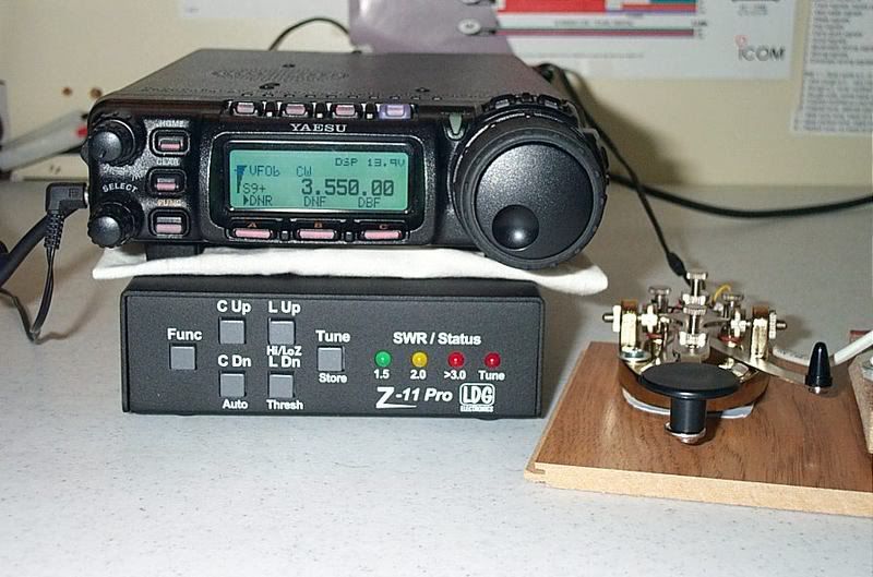 |
I am going to guess that you set up the vhf antenna with a BNC to avoid connecting to the HF output. How much power can you use with that connection? And why not go to N type? What antenna do you use on the HF side? I will assume that you have everything well grounded when operating. Great setup Great setup . .
|
|
Well, I am happy that I stumbled onto doing the same thing. Yaesu 857, LDG AT100 pro tuner, and the SEC 1223 Power Supply. The HF antenna is a Diamond BB7V. Mounted on a 20' Galvi pipe secured to the side of my house. The tip of the antenna is 42' off the ground. I'm a noob General, my call has not been updated yet. I can hear folks all over the country and Japan yesterday but no luck on making a contact. Bummer. Any ideas are welcome, another member of the site has been helping try to make a contact between Portland and Vegas but no luck yet. I'm a little frustrated. |

String a long wire. Less than 50 bucks and world wide with a tuner. Bob |
So this is a better approach than the vertical? |
|
No, you'd be better off with an antenna cut / designed for the frequencies you want to work. A random wire might "tune" but it's really a compromised design. I truly doubt you'll have a "long wire" since that implies it's multiple full wavelengths of the lowest operating frequency (really stinking long). If you really have that much real estate, put up a full loop or delta loop. Plus you need a real RF station ground (meaning a short run of copper strap or braid going to a system of ground rods). While the wire part sounds simple, the grounding most definitely is not. While it's usually good to have an RF station ground anyway, random wire antennas are fed against your station ground. All kinds of RF nasties flying around if you're ungrounded. If you stick with a proven design and a little patience, you'll be fine. Nobody's having wonderful luck on HF right now during this solar minimum, so you're not alone. Stick with 1/2 wave dipole (variants like flat-top, inverted vee, sloper, etc.) or a G5RV for starters. A vertical will need the ground system mentioned about too, since it's probably "half of a half-wave dipole" like the random wire. You'll learn more by cutting your own wire antenna rather than using a vertical as your first antenna too. Grab a spool of 14awg from Home Depot and feed it with coax. If you want multi-band with low feedline losses, feed it with 450ohm ladder line or 300ohm TV twin-lead by using a 4:1 balun. |
i bought it "certified pre-owned" from a ham in my club -- a used Icom IC-706MkIIg is about $700. new, they are around $880. ar-jedi |
+1.
+1. here is a pointer to a G5RV: Ebay ad for quality G5RV antenna see reviews for this antenna here: www.eham.net/reviews/detail/2202
+ a lot. see also www.radioelectronicschool.net/files/downloads/ocfdipole.pdf ar-jedi |
yes, that's exactly the reason. *** ETA see footnote
the IC-706MkIIg only makes about 50W on VHF/UHF. you can push 1000W through a BNC with no problem -- the connector design has a 500V peak rating and a 1500Vrms dielectric withstanding voltage.
i love the N connector, but for this application it was not needed. the BNC is quicker on/off too.
102' G5RV. see link above for specific type.
yes; photos above are for illustration. ar-jedi ETA: i don't recommend running 0.25" diameter RG58 for VHF/UHF, as shown above. my VHF/UHF antenna requirements are minimal, and the Diamond X50 that i have on the end of about 30 feet of RG58 makes the local repeaters just fine. this, however, is not a good setup for longer distance work. even for modest length runs at operating frequencies above 100MHz, it is essential to use low loss 0.400" diameter RG8 type coax (LMR400 or equivalent). the HF coax shown above is RG8X. www.qsl.net/w2va/coax.htm |
|
Hey guys, thanks for the replies and advice. I will look into the G5RV, the reviews sounded really good. I will experiment and if that works out maybe figure something out for the vertical, like camping or something. It is pretty portable so 4x4 camping with it may work out, I'll have to see. I live in a cookie cutter type subdivision on a small lot so I'm a little limited on what I could do with a 100' G5RV unless I ran it along the fenceline but then I would have 5' for elevation. Another option is some type of sloping V I guess, I'll have to experiment once I get some free time. Thanks again for the help. |
|
When I first got started I looked at the G5RV it does what it says it does. Its an easy antennna to tune and a wire antenna is easy to put up if put up the right way. I decided not to go with the G5RV instead choose the Carolina Windom 80. Sometimes I don't like to follow to the crowd. I have very please with how well the windom works and have had no problems with the tuner in the 746pro or the PW-1 amp tunning 80-6. I have tried to tune 160 on low pwewr and it flat refuses. My windom is up about 50 feet with the bottom isloator 30-35 feet off the ground. The vertical antennas are fine but take up too much real estate on the ground with the radials. They take lots of work to make perform like they should . A multiband vertical is nothing but a compromise. I highly recommend the Windoms or the G5RV should do you excellent for about anything you wish to do. |
i would not bother with a G5RV or OCF dipole unless you can get the center section up about 35 feet. the G5RV, in particular, requires that the ladder line matching section be (reasonably) vertical. ar-jedi |
I was going to edit my post after plowing through some more reviews. Some guy had no option but to run it horizontal at about 6'height around the fence and was really happy with it. I could get the center section 25' off he ground maybe 30, I just don't think on one side I could get a 45 degree or I would have leftover line. Not sure if any of that matters though, I will need to experiment. Still seems like 60 bucks is a fair gamble to take. |
maybe my wording above was strong... the point is that with a dipole or G5RV only 6' off the ground at the center, performance will definitely be impaired. it's just physics. will it work to some extent? sure. as for your setup -- if you can get the center 25' up, but are somewhat limited in the stretch direction, get the ends up as high as you can (say 6-8 feet) and then with any "extra" wire leftover make an "L" one way or the other in the horizontal plane as best you can. but do not fold the antenna back upon itself, try to keep the bend angle at minimum 90deg or more. this "L" approach works for lots of folks with space limitations when using longer wire antennas such as the 80m-capable dipoles and G5RV's. the nice thing about a G5RV, dipole, or OCF dipole is that they are relatively inexpensive (to wit, compare with a $400 vertical like the GAP Titan) and you can readily play around with the configuration. tie string to a rock, and hang it in a tree, etc... ar-jedi |

see also the tacked Ham Radio 101 thread: www.ar15.com/forums/topic.html?b=10&f=22&t=604477 ar-jedi |
do you know how you get one? you order it and wait. two months backorder? BAH. i ordered my Signalink USB the weekend before Thanksgiving last year. the UPS guy brought it to my doorstep in March. was it worth it? YES. no fuss, no muss, no fiddling with sound card settings, no redirection of system sounds, and in conjunction with DM780 it will decode PSK31 way down into the noise (you can't audibly hear the PSK tones and it will be decoding with 99% accuracy). it's simple to set up, the supplied cable worked first time through once the internal jumpers were set, and i like it. ar-jedi |
Mine 180 foot properly grounded. I does pretty well. I just do not have room on my tower for any more toys  I can go 800 foot. |


|
OK, FINE, you made me do it. My mini ham shack. Take one Kenwood TH-D7A(G), add one lawn tractor battery in a case, volt meter, one amp charger, and an external mic. Bingo, one small beginners ham shack. I did do the longer term upgrade of a decent outside antenna though. Picked up a cheap used 20 foot tower, added a piece of straight pipe to hold both my TV antenna and my home built verticle di-pole incased in PVC and painted for a stealth install.   I'll eventually get a better transceiver but this works pretty good for now, I run about 4.5 to 5 watts and can consistently hit a repeater 20 miles away. My local repeater I can hit on ultra low power 0.05 watts but have to go to 0.1 to get a decent signal. The elevated antenna makes all the difference. As I like all around communication I don't use a beam. |
"i know vat dat is -- it's an espresso machine. no, vait, it's a sno-cone maker." seriously, though, you are correct. shown above is a mag mount 1/4 wave VHF antenna. i was using it to (1) monitor the local repeaters, (2) monitor NOAA WX radio, and (3) ensure that i had *something* connected to the VHF/UHF RF output on my IC-706MkIIg just in case i inadvertently transmitted on VHF/UHF. the HF output of the radio was connected to a Yo-Yo-Tenna dipole. now then... let me get a word in before the antenna police show up, note that this type of antenna needs a ground plane to work effectively. the little piece of steel that the magnetic base is stuck to is just a leftover spacer from my Toyota Tacoma suspension retrofit. the weight of it keeps the little antenna upgright, that is all. much more useful would be a cookie sheet or other planar metallic surface to provide the counterpoise to the 1/4 wave element. so, do as i say, and not as i do... ar-jedi |
|
After cunsulting several battery manufactures web sights, I calculated out my "overcharge" hydrogen output in the worst case mode. IF my trickle charger would actually maintain a constant 1 Amp charge rate ( mine actually cycles on and off to limit overcharging), my 24 AmpHour battery will produce aprox .01152 cubic feet of H2 per hour. As I normally only have to charge it about 30 minutes every third day, I'm not too worried with the H2 production. Now then when/if I switch to a larger charger/radio/battery it will be something I will have to re-evaluate. Probably will switch to a sealed type and add a solar cell for a constant charge "green" system. , but thanks man, I know you really do care. Not to mention LOVE this hobbie/job.
|
actually, i wanted to ask you how you are feeding that? usually feeding a vertical dipole is tricky because the feedline coax has to come away perpendicular to the antenna for at least a half wavelength or so. otherwise the pattern gets all sorts of hosed up because of the interaction between the lower radiator (counterpoise) and the feedline coax. also, it looks as if you've got a couple of coax turns to reduce shield current, a natural by-product of feeding a balanced antenna (diploe) with an unbalanced transmission line (coax). ar-jedi |
|
Its a dual band verticle di-pole. The elements are hollow copper tubing, you feed the coax up inside the lower one and attach it in the middle. To prevent corrosion I soldered the connections. It has a little 1/4 inch gap between the elements. The PVC is sealed for more protection. I used a cross fitting under it to make the bundle and continued the coax down the center. Also made a nice isolator being PVC since the antenna has its own ground plane. Here's and article for you........... 2m dual band vertical antenna enjoy. |
LOL. My current setup is a Comet SBB-5 on a cookie sheet on the kitchen counter. In this photo, what are you using on the wire ends into the screw terminals on the power supply (yellow insulation)? Are those ferrules? I'm pulling together everything I need for my comms box, but I have to say what's driving me up the wall is the tooling. Seems like every fitting needs its own crimper (PowerPoles, BNC/SMA/etc., ferrules, etc). Argh. |
i call them pin terminals, but i don't know what the "official" name is. they look like this (not the actual manufacturer, just found the pic via Google image search): www.e-shj.com/Product/cable-accessories/TERMINALS/p53.JPG
yes, this is a problem. for Powerpoles, an excellent substitute is a Klein model 1005 crimp pliers -- i think i got mine at Lowes or HD from the bargain bin rack for about $15 a couple of years ago. 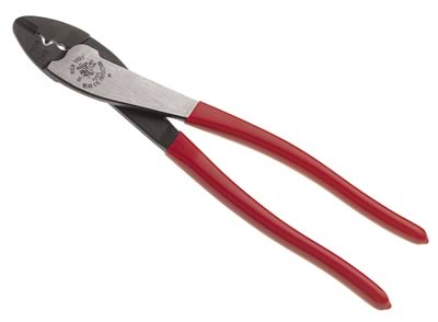 i would not attach SMA's -- too difficult to get right. for BNC's, i would not get the crimp-on type -- get the "clamp-on" type. the latter screw together and are easy (trivial, really) to assemble. so for the most part i make up BNC cables and then use an adapter to get to an SMA. ar-jedi |
See update below
That's what I use - got the $12 tool from Powerwerx.
I misspoke - I meant UHF rather than SMA. I'm planning on using an isolated BNC bulkhead feed-through on my panel with a BNC-terminated cable on the back side & a BNC-UHF adapter on the front side. See update below. I decided against crimp-on UHF and will use soldered UHF. I will use twist-on BNC - see below. So why the clamp-on BNC rather than the crimp-on? |
(1) i didn't want to buy a crimper, (2) you can attach them with an open end wrench, (3) you can reuse them. (*) ar-jedi (*) note that some designs of the BNC and N clamp type connectors cut the rubber sealing gasket as part of the installation process.    also click here: rrsl.ee.washington.edu/medg/connectors/BNC.jpg |
|
ar-jedi, I was just offered this rig: Yaesu FT-897 (the earlier model, not the current FT-897D) with Yaesu FP-30 110vac internal power supply LDG AT-897 Auto tuner LDG FT Meter and the mic and necessary cables Sounds like all I need to do is plug in an antenna. I have an 80 meter dipole now. Oh, almost forgot... all for $750.00. Sounds like a good deal? Anything else I would need? |
based on reviewing the results from a quick search for "897" over on QTH.com, swap.qth.com/search-results.php?keywords=897&fieldtosearch=TitleOrDesc it seems like the radio is priced about right.
two antennas (one for HF and one for VHF/UHF). coax to get from the radio to the antennas. PL259 connectors for the above. ar-jedi |
|
Started out with a MFJ 4125 power supply,used $70 Yeasu Ft857D new $669 LDG Pro 100 Tuner $179 An Antennas & more G5RV 102' $39 A Jetstream 2m/440 verticle $59 Ham radio deluxe program...Free The Steppir 3 element antenna, 70 ft tower, signal link USB, LDG meter, desk mike, IcomV8000 2m radio and paddles all came latter. as did a 204 ft G5RV so I could go 160 meters. 
|
my thread, captured on film, forever!!!  ar-jedi |
I have an 80 meter dipole leading in with RG-8/U, PL-259 on the end. Will probaly do a J-pole for 2m.
I have an Icom R75 already. |
|
A quick update: I placed an order with Mouser a couple of weeks ago. The yellow terminals I asked about are called wire pin terminals. I'm using these from Molex. I am also using a Corcom EMI filtered IEC320 power inlet. I also found a ratcheting crimper that works with all common wire gauges: Harbor Freight to the rescue. This works great for all wire sizes, so instead of having to buy a different crimper for each gauge, or interchangeable dies, I can use this for all power connections/pins/battery terminals. This thing works great and for $13 you can't go wrong. I also decided to go with these solder UHF connectors for RG-213 cable and these reducers for RG-58 cable. I also decided to use BNC connectors for the through-panel antenna jacks, so I bought some of these commercial-grade twist-on BNC fittings and some of these professional-grade twist-on BNC fittings. I have a couple of these coax strippers for the RG-58 and picked up a Cablematic UT-8000 on eBay. For those of you, like me, who don't know anything about RF connectors (though now I do), the Amphenol RF site is a great resource. You can sort by connector type, connection, wire class, wire type, etc. I spent a lot of time there. One thing I'll mention is that the "RFX" series of connectors from Amphenol are the lower-grade commercial fittings and there has been discussion of how difficult they are to solder due to the finish. For my UHF soldered connectors I went with the non-RFX series, but for the BNC twist-ons I'm going to try a few of the less expensive RFX-series items. |
those screw-on BNC's make excellent temporary, field expedient connectors when a soldering iron is not available and/or you need something made up in a hurry. however, i would use standard clamp-type BNC connectors for any other application, including the portable setup you describe above. eventually, the twist-on connectors loosen up, leading to poor or intermittent contact between the connector housing and the braid. ask me how i know this. 
good point. a quick clarification for the folks unfamiliar with the BNC... (1) unlike a PL259, BNC connectors do not require soldering the braid to the housing. a BNC, as illustrated in the Amphenol JPEG i show a few posts back, mechanically clamps the braid to the housing via a jam nut. the only solder that is needed is a tiny, trivial amount to attach the BNC's silver-plated beryllium copper center pin to the coax cable center conductor -- and to do this you need only a very low power soldering iron since the center pin has very low thermal mass. (2) the plating on an RFX series BNC connector is a don't-care from a connector assembly perspective. for ~99.9% of amateur radio applications below 1GHz, the lower cost RFX series BNC connector will be just fine. www.amphenolrf.com/products/CatalogPages/bnc_catalog.pdf
ar-jedi |
the N connector is far superior in terms of constant 50ohm impedance, frequency range, water resistance, and ease of installation. inspect an expensive piece of RF test gear from HP/Agilent, Tektronix, or Rhode & Schwarz and it will have N connectors. that said, the N is overkill for the majority of amateur HF and VHF applications. at UHF and above, the N (and to a lesser extent the SMA) is all you should use. but you should read the following thread anyway, i had it bookmarked... www.eham.net/articles/5300 ar-jedi  |
I recognize that as the ACME micro ranger 160 meter antenna
|
or you can simply put an adapter on the radio's VHF/UHF connector and tighten it real good. example, from the first page of this thread, see losdos.dyndns.org:8080/public/ham/icom-706mkIIg/pics/DSCN3863_sm.jpg and then see losdos.dyndns.org:8080/public/ham/icom-706mkIIg/pics/DSCN3871_sm.jpg those pics should be self explanatory, although it the case above i am using a BNC vs an N. n.b. there is another reason for this approach -- sometimes replacing a SO239 (the UHF female) with an N female is not quite so straightforward. it's not like there is a ton of room inside a modern radio, and there is simply a patch cable from the RF final amplifier to the back panel. ar-jedi |
|
On the subject of replacing the connectors with N's, another comment was "Connectors are UHF-239/SO-239 (standard). Emcomm Gear for a go-kit arguably should be that way to not need an adaptor to use other's antennas." So, just an adapter, and use N's for the rest of the VHF/UHF antenna system? That sounds like the easiest route. |
right on both counts above. ar-jedi |
|
Here's my antenna for 80 meters, 40 meters, and 20 meters. I used some TV mast and brackets screwed to the wood privacy fence along the side of my lot. I put a 3/8" threaded rod in the top, and packed epoxy putty inside the mast tubing to keep it from collapsing. I used lock nuts on each side to keep them from unscrewing. Then a pulley was attached, again, with lock nuts. This is a "dipole" antenna and 50 ohm coax will match with no balun, but a 1:1 "choke balun" will be added when I get some more coax in a few days. Look up "Ugly Balun" via google.  The three sets of legs are, from top down, 80 meters, 40 meters, and 20 meters. They are, 66' each leg for 80 meters, 33 feet each leg for 40 meters, and 16.5 feet each leg for 20 meters. An extra 2' is on each end folded back on itself for tuning.  The center is a piece of 1/4" plexiglass. The holes have been chamfered so it won't cut through the wire. The elements are insulated 14 ga wire. I used three 100' rolls to make this antenna. The ends of the wire go through the holes in the center insulator, wrap back around themselves 5 turns, which is covered with heat shrink to keep the wrapping in place, then back toward the insulator, again covered with heat shrink to secure. In the middle of the insulator is a SO-239 socket. All three legs on the left side come together and are soldered to a short piece leading to a solder lug, which is attached to one of the screws on the flange of the socket. Heat shrink and a rubbery sealant (Seal All) are used on that to seal it up. Also, where the wires all splice together, Scotch 130C sealing tape ("coax seal") is used. This is the thick, stretchy butyl rubber stuff that seals to itself. To keep that all together the bundle is covered with heat shrink, and Seal All smeared over that. The three legs on the right side in the photo are spliced to one short piece that is soldered to the center pin on the other side of the SO-239 socket. That is also covered with a piece of heat shrink and Seal All. On the socket is a right angle adapter so the coax can hang at a more natural angle and not put a kink where it comes out of the PL-259. All of that is sealed up with the Scotch 130C coax sealing tape. The coax is supported by a short piece of rope so that there is very little strain on the PL-239 connector.   The legs are, top to bottom, 66' (+2' for tuning) for 80 meters, 33' (+2' for tuning) for 40 meters, and 16.5' (+1' for tuning) for 20 meters. The ends loop through a short insulator made, again, from 1/4" plexiglass. And the holes have been chamfered to prevent cutting the insulation or rope. 1/8" nylon rope is used to tie from the insulators to eye bolts screwed into the 2x4 rails at the top of the fence. I'll probably replace those with pieces of black 550 paracord later. Black seems to disappear, just not noticed against most backgrounds. Standing under the antenna with the sky behind the black shows up clearly, but at most other viewing angles, the black wire is very unnoticeable. So, I'll replace the white nylon end ropes with either black or OD paracord.   Right now I have this hooked up to an Icom R75 receiver and it seems to be working very well. This should be an easy antenna to tune up via a tuner for transmit. It receives very well down to beacons offshore below 300 khz and the AM broadcast band. I never hear anything in the 160 meter and 120 meter bands. A ham friend says, "I never knew anyone with enough real estate for the antenna for those bands." I'll see how it tunes up for 10 meters later, but I could always add legs for 10 meters, too. |