


Armory Sponsor


Posted: 6/5/2013 4:17:51 PM EDT
[Last Edit: Gorton87][Edited]
|
Link to original thread.
This will be updated as I can hopefully you guys don't beat me up to bad. First part is the conversion info for converting your Sordin Lemo style headsets to work with commercial radios. I will cover these steps: 1. Convert connector to U93 2. Remove PCB inside headset that's no longer used 3. Convert dynamic MIC to an Electret MIC Second part will be a cable and mic delete conversion. I will cover these step: 1. Cable Removal 2. Mic Removal 3. Parts to full the holes to give a nice finished product. Notes on the full conversion: Parts needed: (You can supplement your shrink tubing of choice. I like to use adhesive type. Also the solder of your choice. Do NOT supplement the connector or microphone) U93 Connector: (If you can find cheaper let me know) http://www.westfloridacomponents.com/HW017PD/view.html Electret Microphone: http://www.mouser.com/ProductDetail/PUI-Audio/PNM-5250L-R/?qs=sGAEpiMZZMtcsMZaWNSqu7Rhi7egPHDEurlxxjwu4ww%3d Solder: http://www.mouser.com/ProductDetail/MG-Chemicals/4870-18G/?qs=%2fha2pyFadug04CfCcw2N%252bWJL%252bl6CCpAKDH%2fktACyS5A%3d Shrink Turbing: 1/4": http://www.mouser.com/ProductDetail/Qualtek/Q5-2X-1-4-01-QB6IN-20/?qs=%2fha2pyFadui%2fhp3Xt7zacdVqlv6P%252bwB3avggFuvQW1PmkfEog28dEq9rttsT1jgd 1/16" http://www.mouser.com/Search/ProductDetail.aspx?qs=tEOwSubfllk5IoKXvU%2fWOw%3d%3d Tools Needed: (Links to the units I have) Fine Detail Solder Gun: (Do not use a large one) http://www.homedepot.com/p/Weller-18-Watt-Soldering-Iron-WPS18MP/202077464#.Ua-aWZyv91s Hex crimping tool: http://www.radioshack.com/product/index.jsp?productId=2062636&znt_campaign=Category_CMS&znt_source=CAT&znt_medium=RSCOM&znt_content=CT2032236 Wire Stripper: Any work Cable Stripper: (You can supplement this with a razor blade but be cautious) http://www.radioshack.com/product/index.jsp?productId=2062637 T8 Hand Driver: Any work Small Slotted Screw Driver: Any work Small needle nose pliers: Any work Hot Glue Gun and Sticks: Any work, steal your wifes Heat Gun: Any work, Hairdryer doesn't Razor Blade: Real sharp one works great ----------------------------------------------------------------------------- More when I can.................. |
|
Reserved for step 1
------------------------------------- What the finished product will look like: 
Nexus Wirering Diagram: 
Contact 1: White Contact 2: Green and Yellow Contact 3: Black Contact 4: Grey Brown is not connected to anything and should be cut flush. I will add pictures when I can. Step 1 - Cut Wire Cut the wire right behind the Lemo connector. Use a good cutter, the wires are individually wrapped with metal braiding that can make the cable difficult to cut. I use a pair of linemans. 
Step 2 - Strip the main sheathing back (Outer layer) This is where I use the cable stripper that is typically used for stripping coax cable. I removed one of the blades and adjusted the single blade to strip the cable back and not cut into the wires underneath. You can use a razor blade but be very careful. If you hit a wire inside you will have to cut back and start over. I typical strip back about an inch. This will expose the 6 wires each covered in metal braiding and a string material. 


Step 3 - Removing the Steel Braiding This takes a little time but has to be done. Take each wire and untwist the metal braiding with your finger then re-twist it off the wire. Bend the wire back and cut flush with a razor blade. Do this on all but the Brown wire. On the brown just cut the whole wire and braiding flush. 


Step 4 - Cut the String Flush Some people will actually tie this string around the inside of the connector, I cut it flush. To me this was tedious and I felt it was not needed with how I attach the connector. If you feel the need to attempt I wish you luck. Maybe strip the cable back farther to give you more string to work with. Step 5 - Slide the Housing of the Connector up the cable I can not tell you how many times I have finished up a connector install and realized I did not slide the housing on first. Resulting in me starting all over and throwing the connector in the trash. 
Step 6 - Shrink Wrap Here I take 1/4" adhesive type shrink tubing and apply this around the base of the cable. This does a couple things. It makes the cable tight in the connector housing, gives the crimp ring more to "bite" into, and helps seal the end of the cable. Cut a piece of tubing about 1" and slide it over the cable so it flushes out with the housing. Go ahead and shrink it up with your heat gun. Spread the heat around until you see the glue run out the ends. Do not get carried away as shrink tubing will melt and deform. Now cut a piece about 1.5" and slide it over the piece you just put on. The longer piece will give you the nice stepped up appearance you see in the picture and make it the exact size of the hole in the connector housing. This can be really tight. Make sure the other piece cools and just take your time. Go ahead and shrink this piece with your heat gun. 


Step 7 - Install Connector  Did you install the connector housing Did you install the connector housing
Take the crimp ring and put it over the long stem on the back of the connector. There is a slot for this. Slide your cable and wires through this while holding the ring on the connector. You can not put the ring on the cable then slide the stem in. Doesn't work out. Allow a small gap between the L-bend in the stem and the base of your connector. About 1/16". Take the large portion of the hex crimp tool and compress the ring. DO NOT DO THIS IN ONE STEP. Go about half way and rotate the cable and crimp ring in the tool. This style of crimp tool will break the crimp ring and render it useless and good luck getting another crimp ring.... If you do break it PM me I have some solutions. 


Step 8 - Strip and Solder the White Wire I separated this wire because it was a bit of a learning curve. Take all the wires except the white wire and pull them back along the cable so they are out of the way. A piece of tape or small zip tie works good for holding them back. Reason for this is if any of these wires are touching the stem on the back of the connector when you go to solder the white wire it will melt there sheathing and expose the wire. We do not want this. Once the other wires are out of the way you will see a small hole to insert the stripped white wire into. Go ahead and cut back the white wire to the length required to go through the hole and wrap back around flat. Now go ahead and strip. This can be a pain to get this little guy in there but it will go, just be patient. Go ahead and solder the wire. Use your razor blade to remove the excess solder or wires sticking out. We want a nice clean look. 


Step 9 - Strip and Solder all the other Wires Pay attention to the layout I used up top. You will see a corresponding number above the terminal. On a side note go ahead and squeeze the terminals together better. From the factory they can have a gap and some wires will some times sneak through. To figure the length of the wire to size it I lay it across the terminal and cut it still it just barely doesn't touch the plastic. Strip the wire back enough that there is no sheathing in the terminal. Slide the wire in and solder the wire to the terminal. Repeat this step till you have all the wires landed. On the yellow and green they will share a terminal. Reason for this is one is left earphone and one is right earphone. On the Lemo connector the headset could be dual comm with one channel broadcasting in one ear and one in the other. 
Step 10 - Seal the Connector I take hot glue and seal all the terminals with glue. 
Step 11 - Install the connector housing Slide the connecter housing down and thread into onto the connector. I like to take the small terminal on the hex crimp tool and hold the connector while I get the housing tight with my hand. I have never broken one but I wouldn't push it. 
Step 12 - Cables done! If you are using a military radio (low impedance) or a MSA Icom PTT with built amp you are done. If you are using a commercial radio or standard PTT continue to step 2. |
|
Reserved for step 2
--------------------------------------------------- Going to upload photos here first. I will work on a step by step as I can. Step 1 - Remove the ear cup and foam backer Using a small slotted screw driver gently pry the ear cup off the unit that the mic and cable goes into. Gently pull the foam off. This will review the PCB. 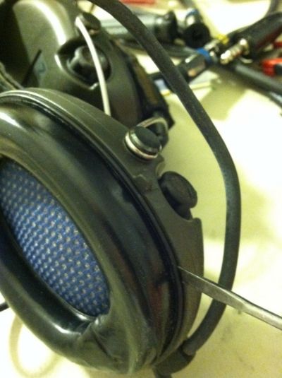
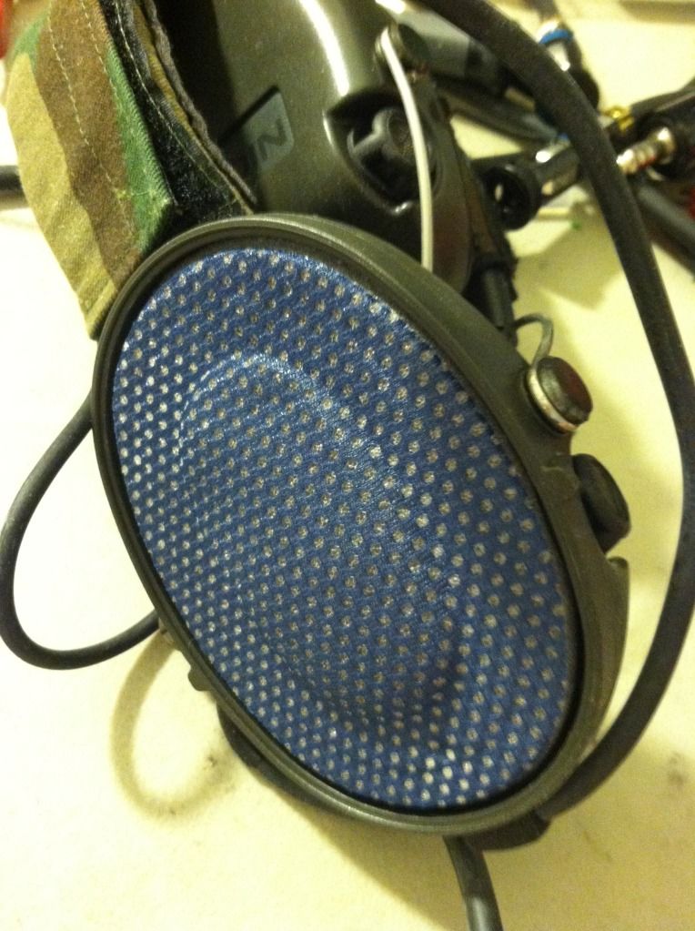
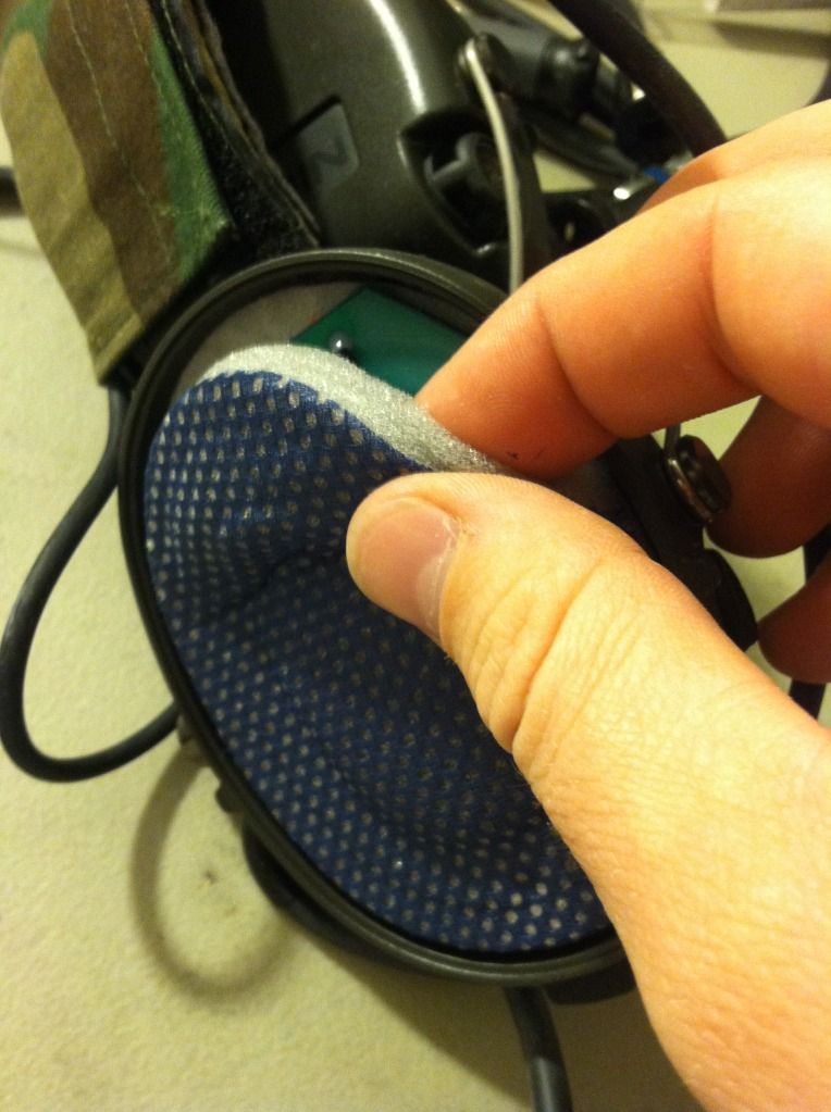
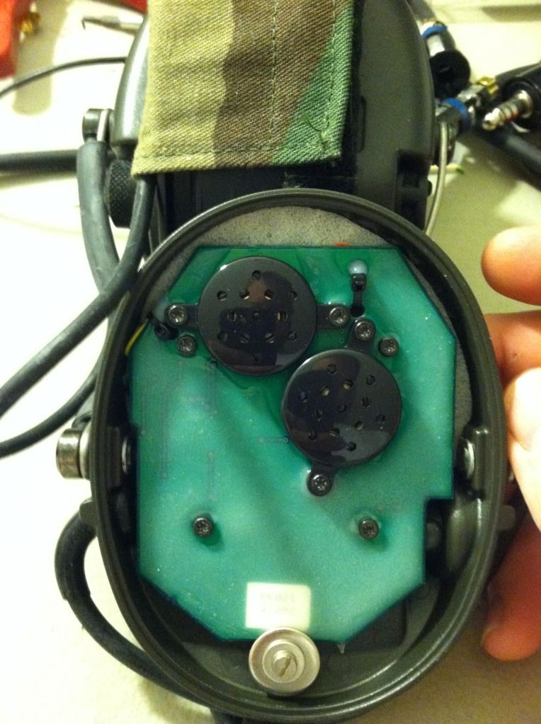
Step 2 - Remove the PCB from the housing There are four T8 screw and a slotted screw and washer that hold the PCB into the housing. Do not remove the screws that hold the speakers in place. Remove these and gently flip the PCB over. 


|





| SSgt, youll have to forgive the dumb question here from a n MP, but Im pretty comm illiterate, so what I was wondering is if this same process would work for a Harris PRC-152 headset to connect it to a Motorola, model similar to a Sabre. I hope you can shed some light on this for me, its going to be a post deployment project. |
|
Originally Posted By Leprechaun5811:
SSgt, youll have to forgive the dumb question here from a n MP, but Im pretty comm illiterate, so what I was wondering is if this same process would work for a Harris PRC-152 headset to connect it to a Motorola, model similar to a Sabre. I hope you can shed some light on this for me, its going to be a post deployment project. Not a dumb question. Do you have the model of the headset? PRC152 is the radio itself. The procedure should be the same but the pin out may be different. I can assist with figuring this out if needed. As to an update on progress... Sorry for the delay working some odd hours this week. I will try to get back on it this weekend. |

| Be aware the saber uses zener diodes to apply different voltages to a pin on the universal connector which which sensed will enable audio on that connector and disable the internal speaker. There should be some info over at the batlabs site. |
I don't know what you are talking about. Sounds like you might be doing drugs or something.
|
Im not positive about the name of the headset, even our comm guy doesnt know the specific name for the headset. I have two,they are both 5-pin with PTT switches.One is black, hooks over the ears and around the back of the head, the second is green, has an elastic band that circles the head and green mesh that goes over the top, it has two PTT options, one that attaches to your gear and another you can run to your weapon system for comm during a fire fight. I tried finding pictures of either online but all I can find is Peltor gear. Both of these are issued headsets. I hope iI've been able to give you an idea of what I have here. I can work on pictures if that helps.
EDIT: The green headset is marked 'HARRIS', according to my comm guy its what is supposed to be sl3 issue with the radio. |

|
Originally Posted By ssgtcarroll:
Some updates. Some damn nice updates. Thanks ssgtcarroll! I've got two pair of the surplus MSA Sordins. This week I received my mic capsules, TP-102 and TJ-102 connectors. They will be used with HX370Ss. I will be looking for PTT assemblies soon, and they ain't cheap. |
"Eh, I'd say Lil' Wayne is... about a 2/3 IPSC."
|
ssgtcarroll,
What glue sticks are you using? I am researching the dilectric properties of some; from the bit I've read the polyvinyl type are a no-go, but the polypropylene type are OK. |
"Eh, I'd say Lil' Wayne is... about a 2/3 IPSC."
|
Originally Posted By FN_form:
ssgtcarroll, What glue sticks are you using? I am researching the dilectric properties of some; from the bit I've read the polyvinyl type are a no-go, but the polypropylene type are OK. Interesting observation. I have tons of them and do not have the original paperwork. Thanks for pointing that out. |


|
Originally Posted By fosters:
I have two sets of sordins..one with the lemo plug and one that is the tp120 dual comm...which would be the better candidate to connect to a yaesu vx8dr? Hand held ham radio? I'm thinking impedance issues and mic conversions item....have the u93a ptt TIA... Looks like we have had a member who did this to VX-7DR and said no issues: http://www.ak47.net/forums/t_10_22/629696__ARCHIVED_THREAD____yaesu_vx7r_compatible_with_peltor_comtacs___.html&page=1#i10747495 And looks like another member had issues and corrected them with a procedure that looks like this: http://www.ar15.com/forums/t_6_10/393881_Peltor_Mil_Headsets_With_Any_Radio___How_To_Do_It.html |

|
I have a question. I recently did the plug conversion to my Sordins and I have a PTT with the amp mod done to it. When the antenna is not blocked by my hand or body I seem to be getting RF interference when I key up. The radio is a Baofeng UV5R+ and the PTT is one of the Nexus PTTs.
Any ideas? Shielding or an RF choke? Any tips please? Thanks. |
|
Originally Posted By DM1975:
I have a question. I recently did the plug conversion to my Sordins and I have a PTT with the amp mod done to it. When the antenna is not blocked by my hand or body I seem to be getting RF interference when I key up. The radio is a Baofeng UV5R+ and the PTT is one of the Nexus PTTs. Any ideas? Shielding or an RF choke? Any tips please? Thanks. This is something I experienced once or twice as well. I never really did work it out so if anyone has some ideas I'm all ears. |
| Wrapping the cable in stainless steel or aluminum insect screening material.and then duct-taping the screening might help a bit. Or try aluminum foil wrap with duct tape. FAR from an ideal solution, but it might help. |
"The M1 Rifle is the greatest battle implement ever devised." General George S. Patton Jr.,US Army

|
ssgtcarroll,
Thank you for posting up this tutorial. I've assembled all the components to convert my headset, I have just one question on wiring the microphone. You show using a multimeter to check continuity of the mic wiring to the plug, I'm assuming this is to differentiate between the + and - for the mic. My question is for the "Microphone, High" and "Microphone, Low" which is the + or - on the mic? (i.e is Microphone, High + or - ?) Thanks |
Pain or damage don't end the world.Or despair, or fucking beatings. The world ends when you're dead. Until then, you got more punishment in store. Stand it like a man and give some back.-Al Swearengen


|
If you still have the connector and can see the colors,
http://www.cryptomuseum.com/crypto/usa/u229/index.htm |
#FreeGrin
I'd rather die on my feet then live on my knees.
I came into this world kicking, screaming, and covered in somebody else's blood, and i have no problem going out that way.
I'd rather die on my feet then live on my knees.
I came into this world kicking, screaming, and covered in somebody else's blood, and i have no problem going out that way.


CHRONIC - Member ....but not a 3rd member
Joined:
Sep 2004
Posts:
76415
EE: 100% (1)
 TX, USA
| I'm gonna bump this for the same reason as above. I have a dual-comm setup coming in. I will be converting the mic element myself using the Mouser/DigiKey part in the How-To... but other than some hot glue and a pair of solder joints... what is missing from the write-up? Is the clear plastic barrier something that was added... or part of the OEM assembly? |

|
Originally Posted By AlexTheSquid:
I'm gonna bump this for the same reason as above. I have a dual-comm setup coming in. I will be converting the mic element myself using the Mouser/DigiKey part in the How-To... but other than some hot glue and a pair of solder joints... what is missing from the write-up? Is the clear plastic barrier something that was added... or part of the OEM assembly? |
|
Originally Posted By ssgtcarroll: OEM It would be nice if I could convert these to the newer MSA/SRS Avenger style electret boom like I've done with some TCI Liberators... but I hate the idea of drilling a new hole and plugging the old. |
| I set Thread Status to Non-Archive. That means it will always be somewhere in this Forum, and won't "disappear" into the Archives. You might have to search for it a little bit, but it won't go away. |
"The M1 Rifle is the greatest battle implement ever devised." General George S. Patton Jr.,US Army
|
Originally Posted By ssgtcarroll: Won't work with it in place. TEA cuts it out as well. Originally Posted By ssgtcarroll: Originally Posted By SIG2f3: Do I have to do anything If I just want to switch out the mic from dynamic to electric? Or do I still have to cut out that PCB that's shrink wrapped? Won't work with it in place. TEA cuts it out as well. Please can you tell me what this PCB is for and why it has to be removed? Is it correctly that if I change Lemo connector for a TP120 I made a 75310 Headset out of a 75305? Would be very nice if you reupload the pics. Thanks for all your great work. |

Link for PTT with Yaesu plug Radio Setup for Fighting Rig |
|
Hoping to get some help with the electret mic install. I ordered the mic from mouser that was provided in the link, but what I received was a 6mm mic. I verified the part numbers and its correct to what was linked. Unfortunately the pictures in the thread have been nuked by Photobucket so I cant see the install. Is this the correct mic for this? Please help, I am at a dead end. Thanks ETA: Thanks for the response SSGT!!. That is the correct mic, I bedded it in hot glue as instructed. I will have some pics if anyone needs assistance since the pics in thread got nuked. But only after I verify function when my PTT gets here. |

Armory Sponsor