


Armory Sponsor

Posted: 5/18/2008 9:46:06 AM EDT
[Last Edit: jackal2001][Edited]
|
Firing Pin Mod by jackal2001
I have seen some reports on the net of people having issues after firing 200 rounds or so then getting light primer strikes or failures of rounds to go off. I picked up a case off the ground at the range that someone else was shooting from another .22 and took it home and ran it in my GSG-5 to show a comparison of the primer strike. The GSG-5 doesn't hit as hard as some other weapons. Out of 550 rounds of Federal Value Pack ammo, I personally had a dozen or so rounds fail to go off initially, but when they were re-fed, they went off. I don't know if it is a light primer strike issue, or there was no primer on those sections of the casing. Update from a GSG email sometime around 4/2/08: "We have improved during the production/assembling of the first lot a little bit the design of the firing pin. So your new firing pin and all other firing pins we have produced after the change have this improvement." Anyway even after using a "new" firing pin that GSG sent me I was still having light strikes so I decided to mod my firing pin. Below are the results and instructions. 2 Left Cases - Factory Firing Pin 2 Right Cases - New Firing Pin + Modifications 550 rounds - 1 Failure to Fire after the mods were done. It was a dead round. 

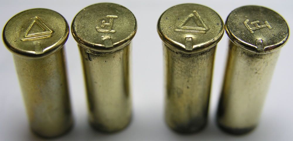
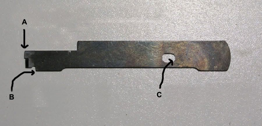
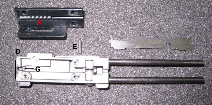
Tools used were a Nicholson Hobby File Set (42030) found at Home Depot or Lowes and you will need a vise to hold the firing pin while working on it. 
Disclaimer: You break it - I didn't buy it. Procedure: 1. Put the firing pin (refered as FP from now on) in the breech block (refered as BB from now on) and push it all the way forward so part B will be up against part G and be in the most forward position. 2. I then examined part A to see if it was flush with D using a new razor blade, only strait edge I had. If part A was not flush, I proceded to file A until it was flush with the BB as shown like D. 3. Once part A is flush with the BB face, we need to file back part B a few thousands. Since we have part A flush with the BB face, we can see how far we are filing part B by how far part A will start to extend past the BB face again. File part B back so part A will extend past the BB face. I did this all by eye and constantly put the firing pin back in the BB in the most forward position where part B goes up against part G. 4. Once you have more part B filed back, you need to re-file back part A so that it is almost exactly flush with the BB face again as shown in D. Get is as best as you can. Again I just used a new razor blade since I didn't have a strait edge. 5. Now that your firing pin has more forward movement, we need to file back the hole, part C, in the FP. Do this while constantly checking the FP by inserting it back into the BB in its most forward postition, B against G, and checking by inserting the pin, part E, to see if it will fit completely through the FP. Keep filing and checking until the pin, part E, slides in with no resistance. 6. Cut 4-5 links from the firing pin return spring, part F. I personally cut 5 off. Reassemble. Note: Do not file down part A so much that the actual striking part of the FP is even with part A. Make sure that part A is still extended past the striking part of the FP. I did this procedure only by eye using the new firing pin that GSG sent me as a replacement. You can see by the thickness of the strike that the FP is thinner. If you want to file yours thinner you can do so as well. Unfortunately there are almost no right angle surfaces to measure with a micrometer, so it almost has to be done by eye. I have tried to do numerous things to my firing pin that shipped with the gun, including peening the back edge to extend the pin, but it started to get smushed by the hammer. Out of all the work that I did, this was the best solution so far. |
|
Modified mags to 10 rounds to be state legal. First off, take the mag apart and load in however many rounds are legal in your state with the mag follower to determine how far the follower travels. 10 rounds will be used here. 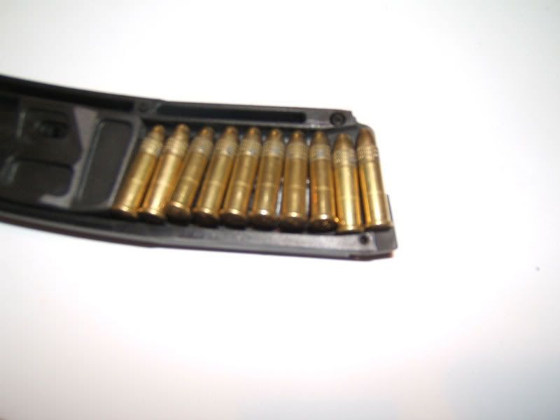 Mark the location of where the roll pin needs to be located. Do on both sides of the mag body. Left and Right.  Drill through the marked location. Do this on both sides of the mag body. You must drill as close as possible to the edged of the mag . 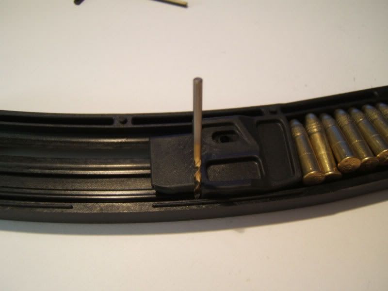 Picture of the drilled hole. You can't really tell in the pic but the hole is more in the curve/round part of the mag instead of on the flat surface.  Picture of the roll pin tapped into one side of the mag body. Note how close the roll pin is to the edge of the side rail on the mag body. When you drill through the mag you basically want your drill bit to drill slightly into the side lip of the mag body. 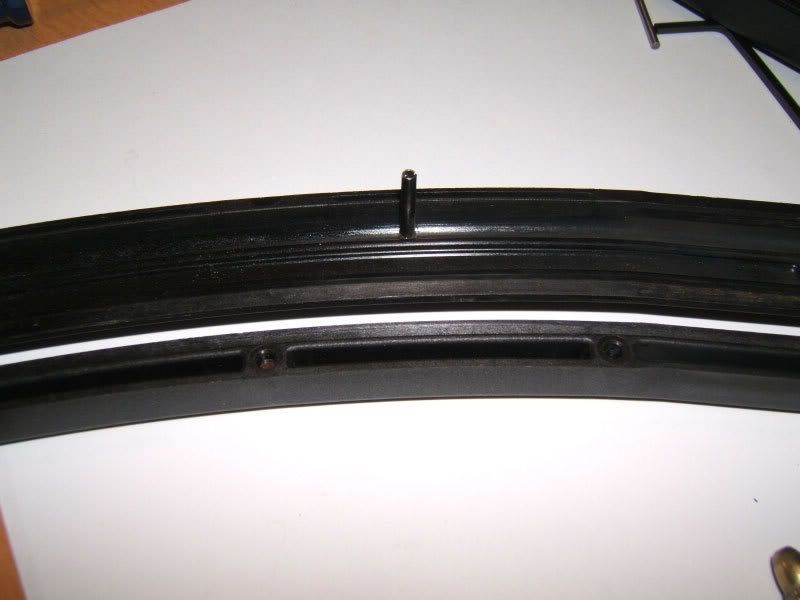 Picture of the roll pin on the one side already inserted and the hole drilled on the other side.  Picture of the roll pin and follower with rounds.  Put the mag together. Then take black epoxy and fill in the holes in the mag. Below is a pic of the first fill of epoxy. Use filler as needed to get it flush with the mag body. After it dries you cannot tell it has been modified and it is permanent. 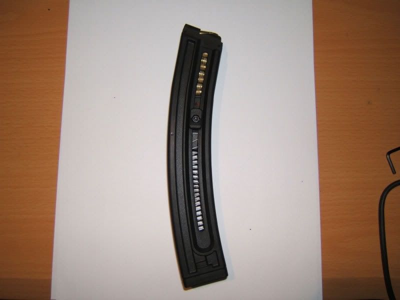
|
|
Delrin Button to keep the Cocking Handle from beating up the housing and breaking off. E-mail [email protected] for more details. 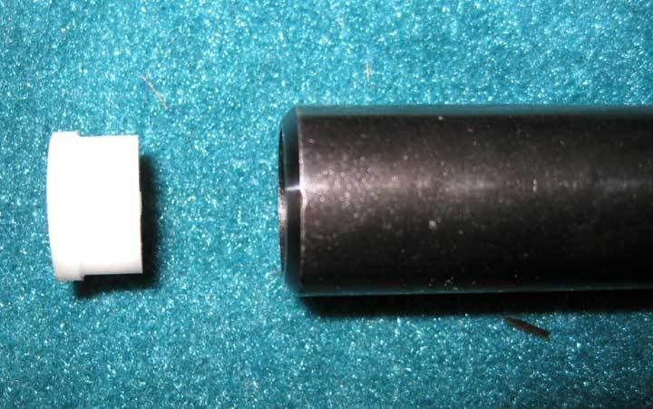 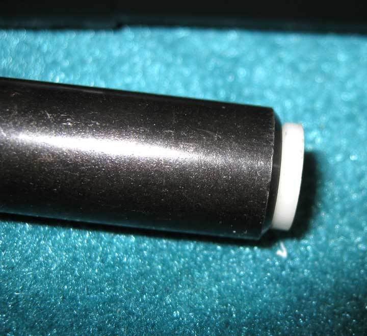  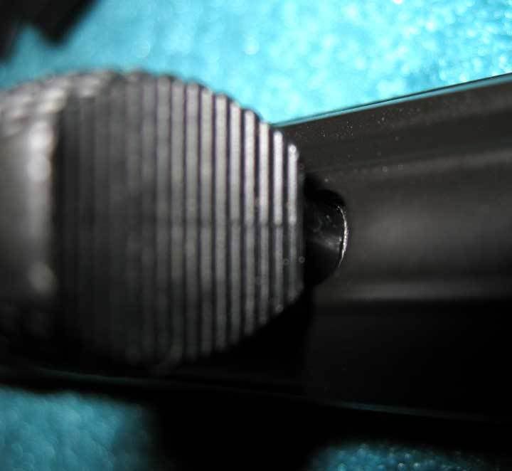 I'm finding the Older First Shipment SG5's have a 2 Piece Cocking Tube and a much more tapered nose when compared to the Newer Version. The Older Version has a much smaller opening in the front where you would install a Buffer Button. Also the length of the Buffer has to be made about 4 times as long as you can see in the Pic below. The Older versions had the Ribbed Cocking Tube Housing while the Newer Version has a Smooth Cocking Tube Housing. Keep this in mind when ordering a Buffer Button. Below: The long version of the buffer is for the old Gen1 made GSG-5. The short version of the buffer is for the newer Gen2 made GSG-5. 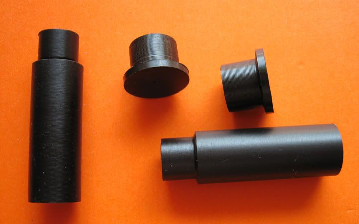 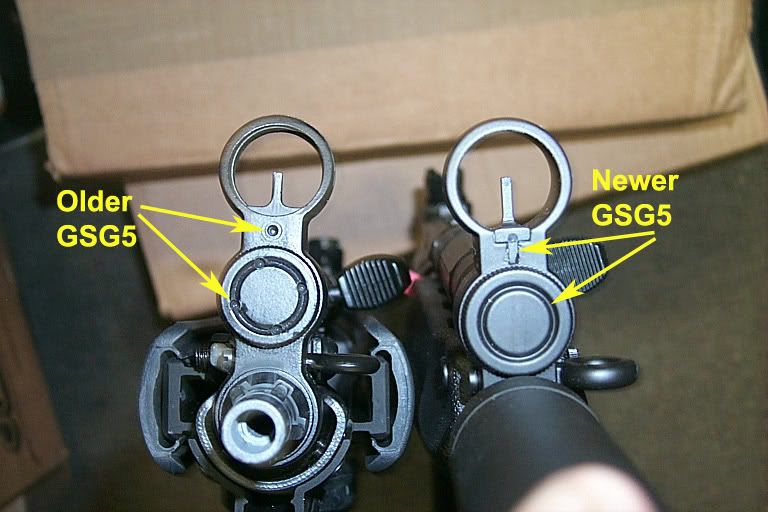
|
|
The majority of the screws on the GSG are a "phillips type" screw. Even though they look like a standard phillips head, they are not. If you look closely you can see there is almost a star pattern to it as well. The only tool that should be used is the Orange Handled Multi-Tool that ships with the gun. A better option would be to replace the screws with hex head stainless steel screws. If you are having problems finding the screws locally you can order them from over in the EE. See links below in the last section. Summary of what to get when shopping at the hardware store: (12) - m3 hex nuts (11) - m3 hex head, .50 thread pitch, 12mm long (1) - m3 hex head, .50 thread pitch, 16mm long (2) - m2.5 hex nuts (2) - m2.5 heax head, .45 thread pitch, 12mm long Location: (4) m3 12mm, with nuts, for the trigger assembly (3) m3 12mm, with nuts, for the bolt assembly (4) m3 12mm, with nuts for the main reciever (1) m3 16mm, with nut - this is the barrel screw (you need this one 16mm to be long enough for the nut to attach (2) m2.5 12mm, with m2.5 nuts for the bolt assemby (these are the slightly smaller screw on the bolt assembly, they have a star hex that is a pain to get out, definately worth it to replace these as they strip easily. Some Pictures of a few of the locations:  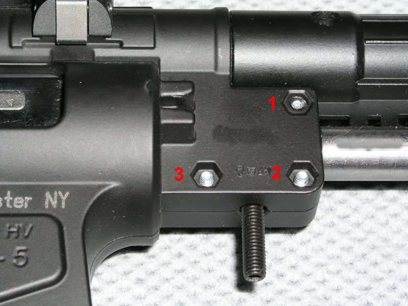 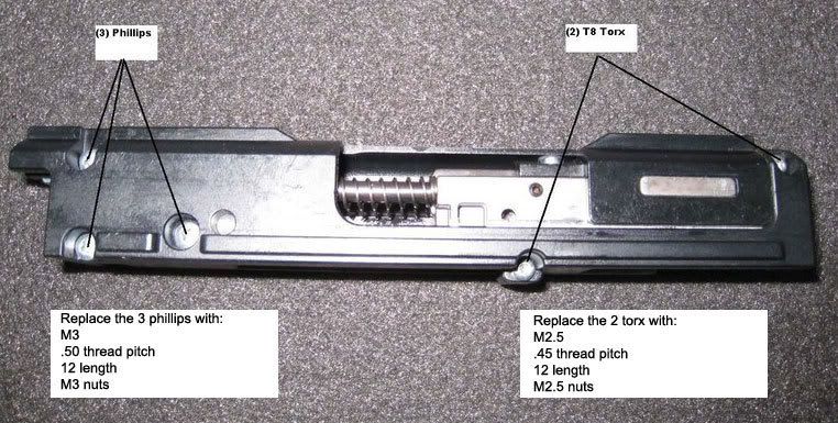 |
|
DISCLAIMERS!!! Remember to make sure the GSG-5 is unloaded and wear prop eye and respiratory protection. This "how-to" is to be considered informational only! You accept ANY and ALL responsibility should you decide to use it to modify the GSG-5. No human, extra terrestrial, or animal life forms were harmed in the process of writing this "how-to", modifications of the GSG-5 or post modification range testing. Parts Used King Arms QD Suppressor (UNCOMPANY / Redwolf Airsoft) Classic Army MP5 front sight (Airsoft Extreme) #8-32 x 3/16" Set Screw (x3 / 2 per a pack from Home Depot) #6-32 x 3/16" Set Screw (x1 / 2 per a pack from Home Depot) 1/2 x 2 copper pipe (Home Depot) 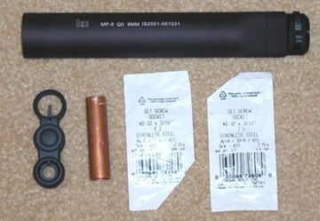 Tools Used Dremel Model 395 - Reinforced cutting wheel (428) or EZ Lock equivalent - 60 grit sanding drum / band (408) - Tungsten Carbide Cutter (9901) - Aluminum Oxide Grinding Stone (8193) Cordless Drill Precision screw drive set #6 and #8 Kobalt Titanium coated drill and tap set - Tap #6 Bit #32 - Tap #8 Bit #29 Fitting the new front sight involves the most work. Take your time and test fit frequently! It's far easier to remove metal than it is to put it back.  Starting with the CA front sight you will need to remove the "notch" from the top of the opening where the barrel comes through the sight and widen the 6mm barrel hole to the current diameter of the front section using the tungsten carbide cutter. DO NOT INCREASE THE DIAMETER OF THE FRONT SECTION ....yet. The diameter on the back side of the sight is larger. DO NOT WIDEN THE FRONT TO MATCH THE BACK. The whole will be to big. Next, take the 1/2" 60 grit sanding drum and "work" it into the front of the barrel opening in the site until you can run the drum all the way through. The hole should be just slightly smaller than the drum and the rounded edge around the hole will help guide the drum. Do not increase the diameter any wider than the sanding drum. If done properly, it will produce a near perfect fit for the copper tubing.  Now flip the sight over and look at the back. There are 4 areas that will need to be modified. Have the GSG-5 handy as you will need to stop and test fit while modifying the sight. Starting with the area that covers the cocking tube, use the 60 grit sanding drum to increase the diameter stopping frequently to test fit. One things to watch for when fitting is that the hole the sling post goes through is aligning properly. You may need to work the bottom part of the area more than the rest so the holes match up. Once the sight starts to slide of the cocking tube, switch to the aluminum oxide grinding stone to "flatten out" the wall as the sanding drum tends to produce a "coning" effect. Again, take your time and test fit often. While test fitting, you will probably notice that the narrow section of the sight post where the sling post screw runs though will needs to be widen slightly. Take the reinforced cutting disk and widen the area using the face of the disk. Again, take your time and test fit often. Ok, so now you got the sight so it fits but it won't go on quite far enough for the sling post to fit through the hole. The back side of the bottom area of the sight where the barrel goes through should not need any modification. However, the back wall of the sight in the narrow section and the cocking tube sections will need additional metal removed to complete the fit. Use the edge of the reinforced cutting wheel to remove metal in the narrow section and the face of the aluminum oxide grinding stone for the area that fits of the cocking tube section. Don't go crazy here. You only need to remove a tiny bit in both section to complete the fit. Again, take your time and test fit often. 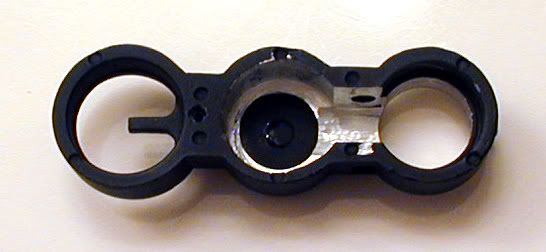 Using the #6 tap and #32 bit, drill and tap the hole in the bottom of the sight. Phewwwwww! The hard part is done! Unscrew the front end cap and QD part of King Arms suppressor and push out the foam inserts. 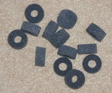 Replace the front end cap and set the main body aside. Take the tungsten carbide bit and enlarge the hole in the QD part until it’s matches the inner diameter. Use the 60 grit sanding drum to smooth out the enlarged area and check to see the copper tube will now fit through the QD part. 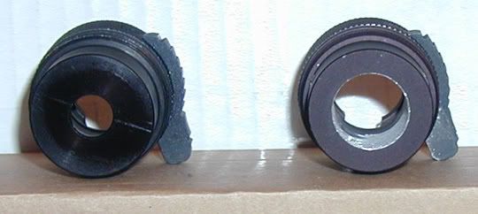 Drill and tap 3 to 4 holes with #29 bit and #8 tap equally spaced. 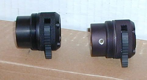 Got the newly fitted front sight attached and secured to the GSG-5? If not, do it now. Cut off a 2” section of copper tube; slide it over the barrel and into the front sight. Slide the QD part on to the copper tube and push it flush with the front of the sight. Install the set 3 to 4 #8 set screws and tighten. Now screw the main body of the suppressor back on the QD part. Rotate the suppressor till you have the markings facing the way you want. Install the #6 set screw in the bottom of the sight and tighten just enough for it to mark the copper tube. Pull the suppressor off. Locate the where the set screw marked the copper tube and drill it with the #32 bit. Replace the suppressor while lining up the hole and the set screw and tighten. DO NOT OVER TIGHTEN! The set screw should be flush with the bottom of the sight. Apply some purple or blue Loctite to the set screws and enjoy!  |
|
This mod can only be done on Gen1 Guns with the ability for the end cap to be unscrewed. You should not use the nut that came with the laser, if you do you will not have enough thread on the laser to get it in. Here a quick guide how I did it: The manual that came with the laser: 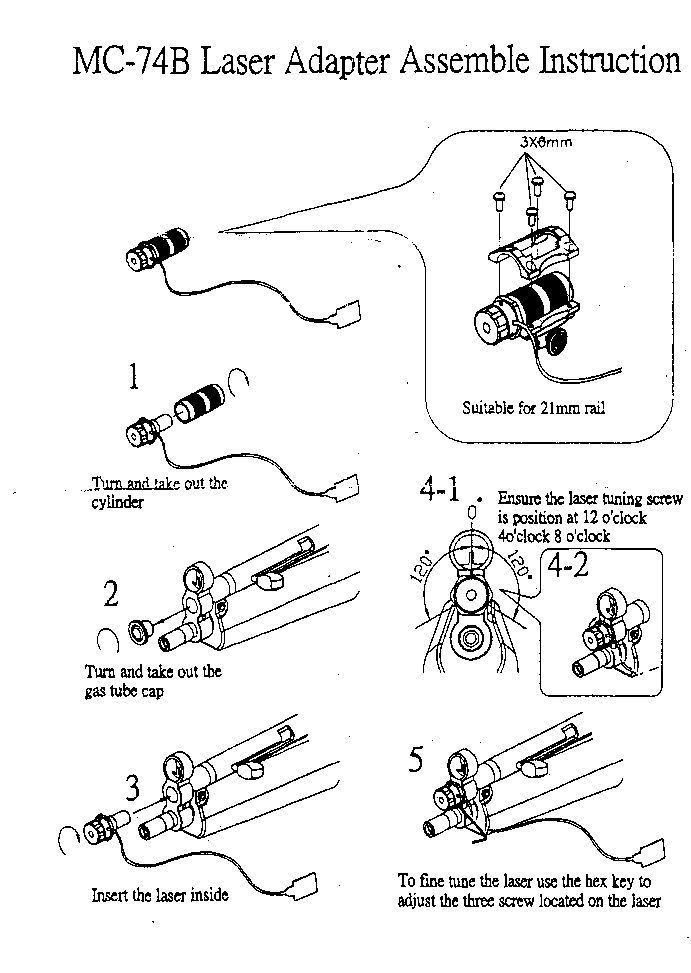 Take the retaining screw out (botom of the fake can): 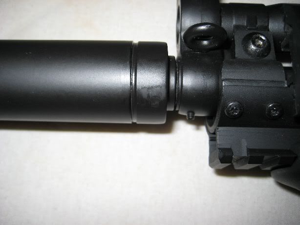 Take the fake can off:  Take the cap out of the cocking tube: 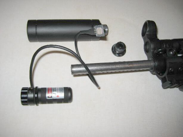 Take the body of from the laser (don't need it): 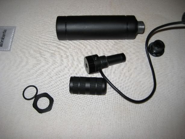 Dremel some material from the bottom of the laser to make the fake can fit again: 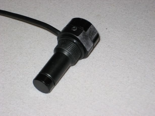 Turn the laser in without the nut (I did use a O-ring but a smaller one): 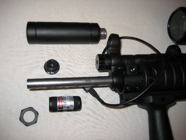 Put the fake can back on: 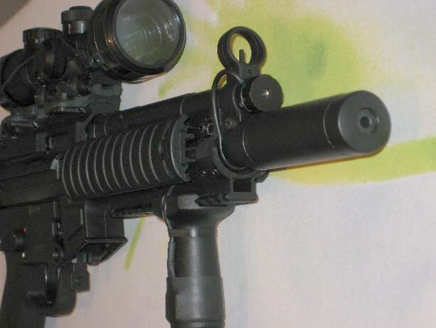 And ready it is: 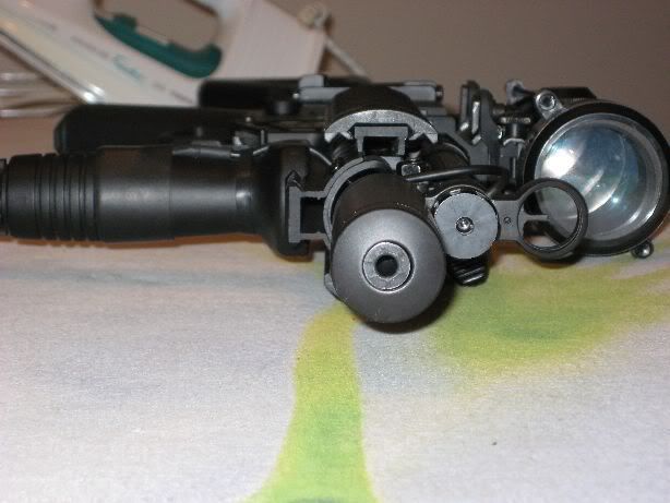 The laser did srew on tightly, because of the O-ring it is secure from movement. I did tight it pretty much using the hexkey that is used for windage and alivation (used it as a lever, but be carefull with that, don't break the hex screws). The upper adjustment scew is now at exactly 12 o'clock. Using the hexkey as a lever secures the laser so much that I can not turn it with my bare hands any more. Tomorow I will go out to the range to test it's "holding zero" capacity. I think it will hold zero just fine because of the 3 srew design, they hold each other in place. EDIT: because of the flat base I dremeld on the botom of the laser it can't be turned any how because the fake can is in the way. If you take care when dremeling and make it a precise fit (best would be to dremel the same radius as the fake can) it will be imposible to move the laser head. The cable switch is attached to the forgrip using some inner tube of a bicycle, the cable is wraped around the front of the handguard, ones around the barrel and out of one of the holes in the front handguard. I did indeed nitch out a little section on the foregrip to put the cable trough. |
|
ICS Navy Lower by Regular122
I received an ICS Navy lower today. What follows is how to fit, modify and install it on the GSG5. Here is a comparison of the Factory GSG5 Trigger Grip housing and the ICS. The ICS has lots of potential because the slots for the rear mounting are there. With the front screw or pin hole and the slotted back end, it makes for a tight fit. In all these comparison pics, the German Sports factory trigger housing is on the left and the ICS on the right. 
The housing looks very nice. The plastic is a little less quality though. And there are some differences that must be modified. But once modified and together with the trigger group, it weighs and feels just fine. 
To modify the ICS to fit the GSG5, here are the main points that need to be cut or reworked: 
What you will need to make these modifications is a Dremel Tool, an X-Acto Knife, a millimeter ruler to measure, and a pencil. Use the pencil to make the marks for the cut. Use the factory housing as a guide. 
It is VERY IMPORTANT to get the placement correct, otherwise, you will have drilled away and the trigger group may not fit becasue it is too far forward or too far back. 
This will take some time. DO NOT GET IN A HURRY. Unless you want a big hole in the side of your nicely marked trigger guard, you need to slowly work the space on the plastic. It is only about 4mm thick. But it is very solid and can be shaped nicely. You will also need to widen the selector switch holes. These are much smaller than on the factory grip and to fit the safety lever, you will need to widen them until it rotates with ease. Do not forget to carve off the little 'stop' bump as this will interfere with the factory selector switch. 
You are now ready to install the trigger group and selector switches. For installing the trigger group, make sure the brass spacer washers are in place and the spring is engaged on the flat retainer that the spacers sit on. Next, slide the group down until the serial block is flush with the top of the housing. Using a small screw driver, gently pry the side open so the serial block can fall into the notch. Then make sure the whole group is flush with the top and that the holes line up for the selector. Install the selector. 
The next step is to install the retaining screw in the hollow of the pistol grip. The ICS has more holes in the bottom, so you will need to widen the main hole into an oval, and then secure the screw base with a locking or flat washer. My ICS did not come with a butt cap. The factory butt cap does not fit. 
Now you can mount the trigger group on the GSG5 like normal. Here it is installed on my 5P. Compare this new look with the inset pic of an actual MP5A3 Navy. 
This project took about 3 hours. The cost of the ICS housing was $29.99 from Evike.com. It shipped to me in about 5 days from order. All in all, I am satisfied with it and am ready to test it at the range. Hope this was helpful to those out there thinking about getting this setup. Steve |
|
ICS SEF Lower Mod by Joel2star
The part you need is BB gun part by ICS MP-46 (mail order from HK cost $35 + $11 shipping) On the right hand side is the GSG factory lower that has been removed from the GSG-5P. 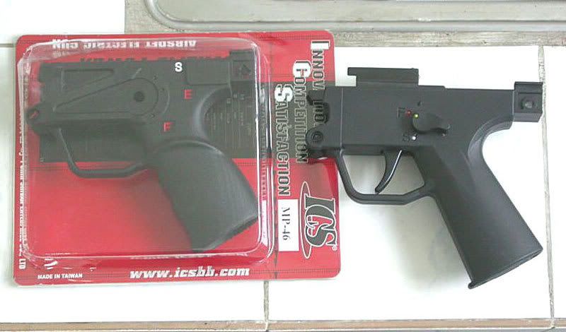
Compare the factory lower (front) to the ICS lower (rear). Inside the ICS lower, you will need to remove (dremel) the two ribs out. These 2 rib are located near the Safety selector hole on each side. You will also note the position of the serial no. cut out on the factory lower. 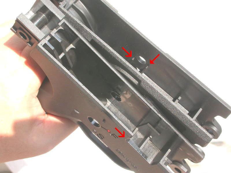
After removing the ribs inside the Navy housing, the entire fire control mechanism can drop in (pretty tight though). But the serial number plate will not fit in. So just mark its' position on the new lower. 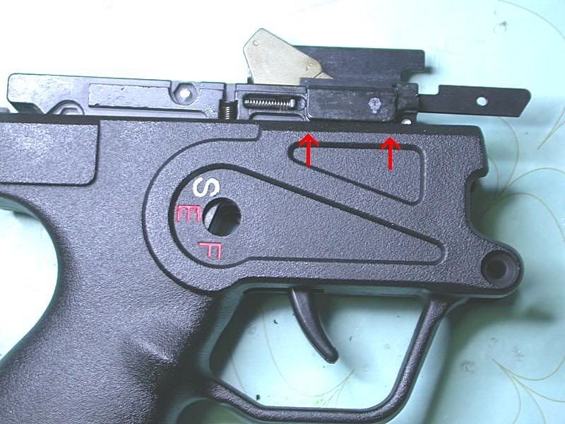
I dremeled (gouging out) 2.5 mil. of plastic inside the new lower at the position marked. Take you time here, and don't over do it. (Sorry for a blurry picture ) 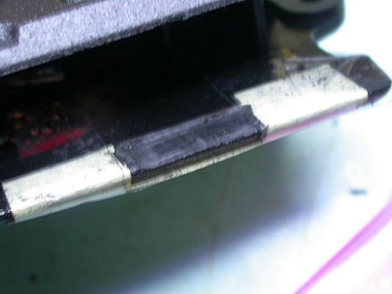
About 30 min. with 5-6 fittings later. The fire control mechanism group will just squeezed in. 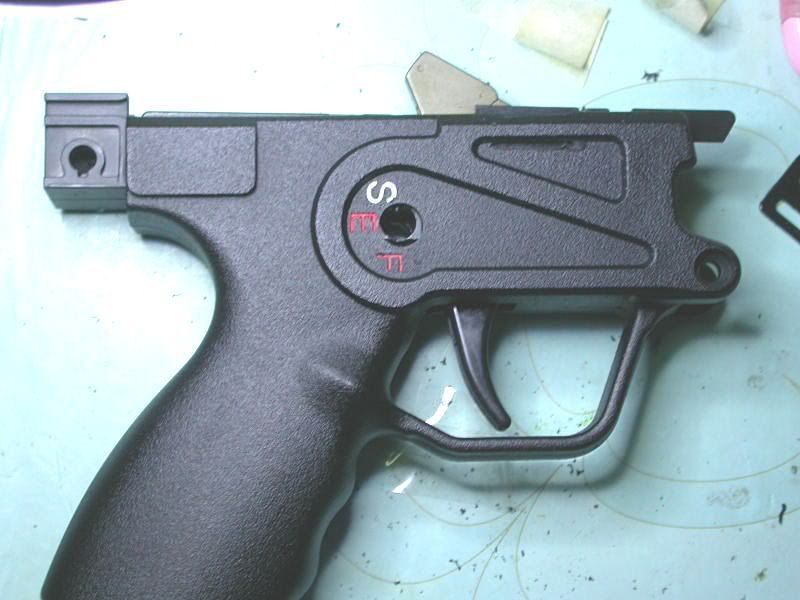
Voila!! 
Next problem, the factory Safety lever is too large to fit into the hole of the new lower housing!! 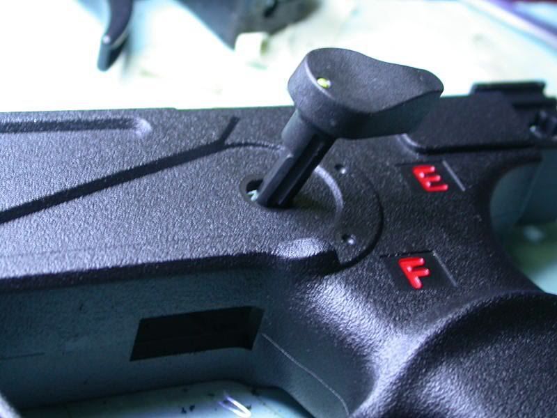
So I had to enlarge the hole radius a bit more using a dremel cone grinder (about 1.5 mm. larger than original) 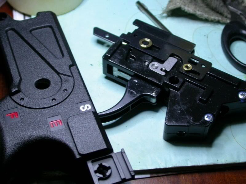
Re-mount the Fire/Safety control lever. Note: It will be stiff to rotate because the outside ridge on the new housing, so I sand the inside of S/F lever a bit to fit. 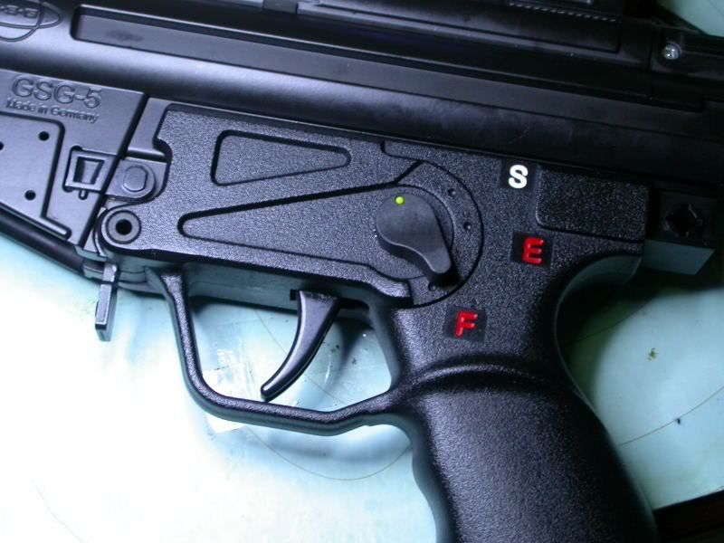
Re-assemble the lower, and that's all to it. 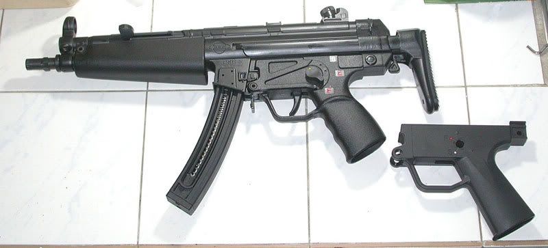
|

|
To me, the GSG-5 felt front heavy, too front heavy. So I decided to do the Great Stuff mod. But before doing so, I sprayed what I thought was the amount it would take to fill the stock and let it set to see how much I would need to spray and for how long (seems like about an 8 count). While I liked the density and knew it would solve part of the problem, I felt it would still be too front heavy. So I grabbed my change jar and started dropping in pennies until I felt the bottom had more than enough weight. Then I started taking a few out and adding them back to see what felt right. Turns out, IMO, that 50 pennies seemed to be just the right amount. So, with the opening facing up I made sure all 50 had been shaken down to the bottom flat and evenly distributed over the entire base, and keeping the stock upright I sprayed in the stuff. I let it set for about 2 minutes and then shook it from side to side and some of the pennies were still able to move so I shoved the straw dispenser as deep as I could, stirred it around and then gave it another 3 second spray. Then continued to shake if from side to side until the pennies were no longer moving. It feels great now. I could have added more pennies and still not been completely balanced, but I feel much better about it than before. I woudl recommend this to anyone, its very easy to do, just make sure to be careful with the stuff. Saying that is extremely sticky stuff is an understatement. And of course you dont have to use pennies, you could use anything with some added weight, it's just what I had available. |
Why settle for only 72 Virgins?

|
you were right 500 rounds and it starts light striking aquilla seems to be horrible CCI works fine still no subsonix ever. are you offering a kit to fix the problem at this time. the can has a 14mm thread that rotates counter clock correct? what cans do you recomened that will swap faux of course |



Take a look up in the buffer section where it shows the differences between the 2 generations. The latest (2nd) generation has a removable front sight post. 1st gen was the older style on the left in that picture and didn't have a removable front sight post. |
|
Just got back from the range, put about 400 rounds through it. Fired semi slow and mag dumped as fast as I could pull the trigger. The sun was in my face, so I shot it at 10 yard (the furthest I could see the laser in the light). 2 groups were shot of 20 each, firing from a steady position, 1 by me and 1 by my buddy. It shot 2 inches low and varied left/right of center 1". His group had the same result. I'll be going back out when it' dark to shoot @ 25 yards, but off center windage wise @ 10 yards doesn't have me expecting much =\. I'll post back with an edit with update later today. Edit: regarding the bullets shooting 2 inches low, I measured from barrel to laser, at 10 yards it shouldn't be that low. Second edit: Good news, I shake like a kid on a sugar high, my earlier findings were flawed. From bench rest @ 25 yards in lower light conditions the laser is accurate and hits the same place zeroed on Friday. For those on the fence about consistency, go for it. The laser holds zero past 500 shots. Make sure to follow the instructions - use an o-ring a bit smaller in diameter than the one supplied and you're golden. |
I already replyed to your personal message but here it is for the rest who is interrested. The laser is rock solid in my GSG, I did make a little mod to it, when releasing the cocking tube the laser would sometimes fail to work. The batteries did not make good contact with the endcap of the laser unit because of the blow, I took a spring from a ballpoint and cut 1/3 of, this part I put between the endcap of the laser and the batteries. The laser endcap has a little notch that holds the spring in place, so problem solved. I did zero the laser ones and it still holding (after 1000+ rounds). The desingn makes it solid, the 3 adjustment srews hold each other in place, tighten them well (don't over do it) and you wil have no problem with this laser. |
|
Barrel mod : A hell of a job, but the success is there! Due to barrel/chamber problems, retractor problems and miss-fires, I took a lot of time to machine a new barrel+fitting to overcome a lot of problems. What did I do : I cut off the last 25mm of the barrel(chamber side), made a new .22LR chamber inside the barrel, and machined the rest of the barrel as original. (I also had to shorten the extention tube by 25mm). Trick is that the M9*1 CCW original barrel-thread, has been replaced by a M11*1 CW thread. Due to this the chamder ridge/edge went from 1mm to 3 mm ! This allowed me to make the retractor groove better to fit the retractor clip in the breech body and made a much stronger chamber for the 22LR ammo! Since I did not want to change the fitting block the barrel fit’s in, I made a new aluminum version and made a M11*1 thread in it. (full day work…. pffffff). The result is astonishing: firing 1000+ CCI Mini Mag, not a singe scratch or damage could be found on the barrel, the retractor of elsewhere. Even not one miss-fire ! I informed Michael Swoboda on this……… for everyone who want’s to do this : take your time !    |

Now that's some great work! Too bad GSG didn't do it that way to begin with. |
None of them "have" to be done if you are happy with everything. The only thing I do recommend is blue locktite every screw. |

Good idea but be carefull. I tried this myself yesterday and ended up screwing my stock up instead. You have to be very carefull when you fill the thing up, DO NOT OVERFILL. After putting my pennys in they would not stop rattling so I continued to add foam, I guess i put too much. I had foam coming out the buttplate, the sling holes, and the top. So after getting this sticky crap all over the stock I used the only recommended cleaning solution which was acetone. Unknown to me but acetone melts plastic so my stock looks like shiester now. So try this mod at your own risk. |
I did the mod (cutting 4 links off) I am not sure which way to put the spring back in  it has a metal insert in one end does that touch the firing (market "E") or does it go the end (market "D") in your pic it look like it at the D but I really what to be sure... it has a metal insert in one end does that touch the firing (market "E") or does it go the end (market "D") in your pic it look like it at the D but I really what to be sure...Man I really tried to take my time a watch the position and orientation but did seem to do a great job at spotting stuff Hmmm Best Andy |
|
thanks man.. thats what I did but great to have it confirmed cheers Andy
|
|
Originally Posted By jackal2001:
Ejector Plate Fix using flat head screw instead of rivet. - by 00boto On one of my GSG's, I used an M2 counter sunk flat head which is just as solid as a rivet. You can get all of the hardware needed for this job at www.mcmaster.com. Hardware Needed - Drill Press or Hand Drill (if you feel like you can hold a hand drill straight) M2x.4 Drill and Tap Set (Drill bit is usually a 1.60mm drill bit) 4mm drill bit M2x0.4x6mm Flat Head Screw Finished Product Below http://i706.photobucket.com/albums/ww65/00boto/GSG001.jpg Instructions 1. Drill 1.50-1.60mm (drill that comes with tap) hole in center of circular tab. The tabs are not quite punched in the center so take your time and get the hole centered and straight. 2. Tap the hole with M2x0.4 tap. Use oil while running the tap through the hole 3. Use 4mm drill bit to counter sink ejector plate so that the flat head screw will sit flush with the ejector plate. 3. Use M2x0.4x6mm flat head screw with RED loctite to secure the screw. You don't want to ever have to remove this screw so use RED. Hope this helps! I just fixed mine per your idea and I wanted to check the picture because I may have drilled it to far back on the firing pin. Now there is no picture for me to check it. Can you repost it? |
|
Decided to post a run down of mod's/enhancments I did to my new GSG-5. Had it about a week, put about 500 rounds through it. Flawless operation and very accurate.
On day one I completely dis-assembled the gun (following Jackal's excellent instructions) and cleaned all the factory oil and lube from all parts. I went back with Rem. Dry lube and some strategic drops of Rem.Oil. Also used a small dab of grease on the drop-safety spring, since it is captive on both sides and will effect the "feel" and smoothness of the trigger's 1st stage operation . I Re-assembled the gun with Blue lock-tite on all screws in the frame, barrel, breech-slide and trigger. (Most important step of all) I removed the magazine safety, but that tuned out to be a mistake. It resulted in magazines being very loose and wobbly when inserted into the gun, so much so, that not only was it annoying, but it would effect the feed of bullets into the gun, IMHO. I put the magazine safety back in, and would not recommned removing it. The magazines were steady as a rock after putting it back again. While I was in there I did a few other things. In the frame I noticed that the guide-rod, for the charging-handle spring, rotated and rattled in the frame where it sits. That caused the charging handle spring to have roughness in it's operation and a cheap "slinky" sound when cocked. To fix this I simply tucked some small pieces of dense foam around the rod. Cocking of the gun now operates smoothly, with no movement of the rod and no cheap sounds. http://i153.photobucket.com/albums/s223/watsongrg/GSG-5011.jpg http://i153.photobucket.com/albums/s223/watsongrg/GSG-5012.jpg Next I decided to make a buffer, as others have done, for the charging handle, so it would not slam into it's slot in the frame when released. In the plumbing Dept. at Home Depot, I found a couple items that were the proper 11/16" outer diameter size, that worked perfect. The (Danco brand 3/8L faucet stem repair) beveled washer and o-ring, stacked together make a buffer with a little "cush" for the cocking tube to travel forward into, without damaging the handle or frame, and it eliminates any cheap metalic noise when the handle moves forward after cocking the gun. I was able to install these items, without seperating the frame halves, by inserting them horizontaly, into the cocking-handle slot, and then turn them into position, and used the charging tube to "ram-rod" them into position, with a couple pulls and releases. http://i153.photobucket.com/albums/s223/watsongrg/GSG-5020.jpg The pieces are oriented like on the pencil tip below, the cocking tube hits the o-ring. http://i153.photobucket.com/albums/s223/watsongrg/CopyofIMG_0680.jpg http://i153.photobucket.com/albums/s223/watsongrg/GSG-5019.jpg http://i153.photobucket.com/albums/s223/watsongrg/GSG-5013.jpg Next, I decided to polish the key parts that make for a really smooth semi-auto firearm. The trigger sear, hammer, and breech slide. I used a 3-piece manicure file set that you can buy for $1.50 at most any store that has a beauty/grooming isle. http://i153.photobucket.com/albums/s223/watsongrg/GSG-5009.jpg With these files you can safetly polish any metal surface to a mirror finish, without worrying about changing the real shape or profile of the hammer or sear. I did the sear and associatied hammer release surfaces (no pics) and the bottom edge of the breech-slide and hammer-face contact surfaces. These meet everytime the slide cycles to cock the gun'ss hammer. http://i153.photobucket.com/albums/s223/watsongrg/GSG-5002.jpg http://i153.photobucket.com/albums/s223/watsongrg/GSG-5004.jpg hard to see mirror finish http://i153.photobucket.com/albums/s223/watsongrg/GSG-5010.jpg The result is buttery smooth operation of the charging (cocking) handle, trigger pull, and firing-cycle operation of the gun. And a neat little rifle that will stay together for years to come.... These target were 30 yards standing(right) and 60 yards resting arm (left) http://i153.photobucket.com/albums/s223/watsongrg/GSG-5003.jpg All I can say is WOW, with a big smile on my face. |
|
15-round mag into 24-round mag
I got fed up with not being able to find any 22-round mags for my PK. So I purchased a 15-round mag at the range the other day. They had about 9 of them there. After reviewing the mag, I came up with an idea. I modded it to take 24 rounds. That's right, 24 rounds! DISCLAIMER. Check you own State's law before proceeding. Mod at your own risk. I'm not responsible for your action or decision. You'll need: One (1) 15-round mag. The GSG tool that came with your riffle/pistol. A 9/64 drill bit and an electric drill. A Dremel cutting bit that looks like a drill bit. And a Dremel. If you don't have this, might be able to work with drill bit. I can't find my camera cord, so I'll post picts tomorrow. Here are the steps: 1) Take off the 2 screws on the top of the mag. And the 2 screws on the bottom of the mag's base. And lastly, the hex bolt on the follower. 2) Carefully pry the two halves apart. The lower spring base, not the cap, is slightly epoxy to the stopper piece and also to one of the mag's side. http://i38.photobucket.com/albums/e121/fourstardrift/GSG5PK-mag-apart.jpg 3) Once apart, you can pry off one of the stopper that's on the rail of the mag. 4) Use the 9/64 drill bit to drill out the other pin of the stopper to the lower spring base. You'll only need to drill out one of the two pins, since only one is epoxy to the lower spring base. Use the drill bit to punch out the other pin to the base. Now take off the stopper on that rail, and the lower spring base. http://i38.photobucket.com/albums/e121/fourstardrift/GSG5PK-mag-parts.jpg 5) The epoxy might have spilled onto the rail of the mag, so this is where the Dremel comes in. Just use it to smooth out the rail so the follower will slide smoothly up and down the mag. Make sure you clean out any plastic pieces that might come from the Dremeling. 6) Apply some grease, if need to, and assemble the mag back together. Leave the lower spring base out, and use use the base cap. There are two small posts on the cap to help keep the spring in place. 7) Now load up 24 rounds of .22LR. Have fun!!! http://i38.photobucket.com/albums/e121/fourstardrift/GSG5PK-full-mag.jpg |
|
Originally Posted By jackal2001:
[div style='text-align: center;']Phillips Type Screw Replacement</center id=center> [div style='text-align: center;']Replaced with Hex Head Stainless Steel Screws and Nuts</center id=center> The majority of the screws on the GSG are a "phillips type" screw. Even though they look like a standard phillips head, they are not. If you look closely you can see there is almost a star pattern to it as well. The only tool that should be used is the Orange Handled Multi-Tool that ships with the gun. A better option would be to replace the screws with hex head stainless steel screws. If you are having problems finding the screws locally you can order them from over in the EE. See links below in the last section. Summary of what to get when shopping at the hardware store: (12) - m3 hex nuts (11) - m3 hex head, .50 thread pitch, 12mm long (1) - m3 hex head, .50 thread pitch, 16mm long (2) - m2.5 hex nuts (2) - m2.5 heax head, .45 thread pitch, 12mm long Location: (4) m3 12mm, with nuts, for the trigger assembly (3) m3 12mm, with nuts, for the bolt assembly (4) m3 12mm, with nuts for the main reciever (1) m3 16mm, with nut - this is the barrel screw (you need this one 16mm to be long enough for the nut to attach (2) m2.5 12mm, with m2.5 nuts for the bolt assemby (these are the slightly smaller screw on the bolt assembly, they have a star hex that is a pain to get out, definately worth it to replace these as they strip easily. Some Pictures of a few of the locations: http://i328.photobucket.com/albums/l340/GSG5Host2/screwreplacement/barrelbolts1.jpg http://i328.photobucket.com/albums/l340/GSG5Host2/screwreplacement/barrelbolts2.jpg http://i328.photobucket.com/albums/l340/GSG5Host2/screwreplacement/GSGboltreplacement.jpg Complete Replacement screw sets avilable here: GSG 5 Replacement Screw Sets |
|
Originally Posted By knedrgr:
15-round mag into 24-round mag I got fed up with not being able to find any 22-round mags for my PK. So I purchased a 15-round mag at the range the other day. They had about 9 of them there. After reviewing the mag, I came up with an idea. I modded it to take 24 rounds. That's right, 24 rounds! DISCLAIMER. Check you own State's law before proceeding. Mod at your own risk. I'm not responsible for your action or decision. You'll need: One (1) 15-round mag. The GSG tool that came with your riffle/pistol. A 9/64 drill bit and an electric drill. A Dremel cutting bit that looks like a drill bit. And a Dremel. If you don't have this, might be able to work with drill bit. I can't find my camera cord, so I'll post picts tomorrow. Here are the steps: 1) Take off the 2 screws on the top of the mag. And the 2 screws on the bottom of the mag's base. And lastly, the hex bolt on the follower. 2) Carefully pry the two halves apart. The lower spring base, not the cap, is slightly epoxy to the stopper piece and also to one of the mag's side. 3) Once apart, you can pry off one of the stopper that's on the rail of the mag. 4) Use the 9/64 drill bit to drill out the other pin of the stopper to the lower spring base. You'll only need to drill out one of the two pins, since only one is epoxy to the lower spring base. Use the drill bit to punch out the other pin to the base. Now take off the stopper on that rail, and the lower spring base. 5) The epoxy might have spilled onto the rail of the mag, so this is where the Dremel comes in. Just use it to smooth out the rail so the follower will slide smoothly up and down the mag. Make sure you clean out any plastic pieces that might come from the Dremeling. 6) Apply some grease, if need to, and assemble the mag back together. Leave the lower spring base out, and use use the base cap. There are two small posts on the cap to help keep the spring in place. 7) Now load up 24 rounds of .22LR. Have fun!!! BEEN 8 DAYS WHERE ARE THE PICS? you posted you did thid mod in another postr, so I came over here tolook & no pics  
|


| Okay guys. I picked up my new gsg-5p on Friday. I found the grip to be uncomfortable, so I took a Hogue slip-on grip sleeve from one of my Sig 225's and it helps a lot. I took the gun a part and cleaned and oiled it. When I got it back together, when cleaning up I found a stray spring on the floor. It is about 1.5cm long and about 1.5mm wide. Question: Where the heck did that come from? |
|
Originally Posted By knedrgr:
that's the spring for the bolt-open/empty mag lever on the receiver. It just goes between the receiver and the lever in the mag well. How does it go in? Ah. I found this in another thread: Originally Posted By jackal2001:
The Missing or Flying Spring Last Round Bolt Hold Open
Most people have encountered a problem with the bolt hold open feature of the GSG-5 not working correctly. There is a tiny spring that sits behind the breech-housing that can easily fall out when removing the breech-housing for routine cleaning. Below are pictures of the proper location of the spring. These are pictures looking directly into the breech/ejection port of the weapon.
|
Armory Sponsor