


Armory Sponsor

DIY Annealing Machine (Page 3 of 17)

|
Originally Posted By rcav8r:
Just found this topic. Goes to show I should go through the reloading forums more often. I already had the motors, controllers, and switches for the rotating annealer, and had the plates waterjetted at work. Just haven't gotten around to building it since it's more of a winter project thing, and spring rolled around at the time. However, I'm liking this one better. I can dump a bunch of cases in the hopper and let it run. Whereas with the rotating one, I'd have to feed the cases as it went along, since I'm not about to spring for a case feeder. Watching the video, I'm not sure what's "kicking" the case loose after annealing. Anyone care to enlighten me? Oh, and I'm in the 2 motors camp. It's a LOT easier to wire them up than to mess with gears, chains, belts, and whatnot. ETA: to be clear, I'm talking about the other one with the blue catch tray. Sorry not following you.... are you talking about the other homebuilt annealer or this one? This annealer uses a cake pan with with a slot cut in to it. it is where the case falls into the drum and out. |
|
Originally Posted By Crazyrcflier:
I am interested in building one of these also. I am in the one motor camp. I was curious if there might be a problem with the single motor having enough torque to turn everything. Is the front of the machine angled at all? What's everyone's plans to cut the cake pans off to length? In the inspiration video, what is the feeder drum made of? It looks to be plastic. I don't have a lathe or anything fancy so plastic would be easier for me than metal. I have thoughts on how to make make it with a single motor. its fairly simple but its still going to cost more than two motors by the time you buy bearings, pulleys, chain/belt. the shafts are more complicated to make. its not nearly as home build friendly. I do not think there will be a torque issue since there is hardly any load....bearings are going to be the biggest killer. I think i might chuck my pans up in a lathe or i will use a cut off wheel. it depends how good of mood my machinist is it. Skip made his feeder out of plastic. |


|
Originally Posted By tstuart34:
I have thoughts on how to make make it with a single motor. its fairly simple but its still going to cost more than two motors by the time you buy bearings, pulleys, chain/belt. the shafts are more complicated to make. its not nearly as home build friendly. I do not think there will be a torque issue since there is hardly any load....bearings are going to be the biggest killer. I think i might chuck my pans up in a lathe or i will use a cut off wheel. it depends how good of mood my machinist is it. Skip made his feeder out of plastic. Originally Posted By tstuart34:
Originally Posted By Crazyrcflier:
I am interested in building one of these also. I am in the one motor camp. I was curious if there might be a problem with the single motor having enough torque to turn everything. Is the front of the machine angled at all? What's everyone's plans to cut the cake pans off to length? In the inspiration video, what is the feeder drum made of? It looks to be plastic. I don't have a lathe or anything fancy so plastic would be easier for me than metal. I have thoughts on how to make make it with a single motor. its fairly simple but its still going to cost more than two motors by the time you buy bearings, pulleys, chain/belt. the shafts are more complicated to make. its not nearly as home build friendly. I do not think there will be a torque issue since there is hardly any load....bearings are going to be the biggest killer. I think i might chuck my pans up in a lathe or i will use a cut off wheel. it depends how good of mood my machinist is it. Skip made his feeder out of plastic. The shaft is not difficult at all to make. Screw bearings to the metal housing, run a standard bolt through it and the rotating piece and bolt it down... Standard hex bolts are 8mm, doesn't get any easier than that! <- I think, haven't built it yet... still waiting on parts.. Skips feeder is made out of PVC Acetal bar stock, you can buy it from Grainger (and pick it up locally) but you have to buy 1ft lengths and it's around $20. Grainger Link You probably want model 2XMH9, 2" x 1ft for $19.70. I haven't figured out what I'm going to use yet... I might just break down and buy that from grainger, I have one 5 minutes from my house 
He stated on one of the pages (3 I think) that he used 50x50mm, which is ~2" by 2".. Sucks you have to buy a foot to use 2"... I might just buy it and cut some off and offer it to you guys if you are interested? Skip also threaded it so you can put screws in one side (to prevent a case from loading).. That's an excellent idea too.. Here is the picture from page 4: 
As an alternative, you could just use metal bar stock (like aluminum) and cut groves in that.. A little more work, but actually probably cheaper when you consider how cheap Al is? |
NRA Life Member
Second Amendment Foundation Member
Second Amendment Foundation Member
|
Originally Posted By GWhis:
If you are thinking that way, just use a short piece of 6" PVC pipe. Sand it smooth on the cut and glue a piece of acrylic to it.....making your own cake pan. No rounded corners...paint to make your color scheme. I think you'll find that would melt, it's right close to the flame path. Personally I would use a 2" wide strip of 1/16 metal and wrap it round a wooden disc about 4-5 " in diameter and maybe 1/2 inch thick. Screw it in three or four places. If you were to elongate the screw holes you could vary the depth of the "pan" for different calibres. Also cutting a slot or the rim off a cake/paint tin will leave sharp edges that would be difficult to dress. |
|
The above is correct.
I used 50x50 ( cnc off cuts ) from a friend for $40 for about a meter worth if they wernt cut. I made some feeders up for members on our forum ( both feeders & drum coupler ) i charged $20+ post for each member. For the annealer drum its ally 25x40mm ( 22mm for the m8xthread bolt & 18mm x8mm shaft with a m5 grub screw ) The case feeder the slots was ( 15mm wide x12mm deep and small feeder was 10mm wide x 9mm deep for the small cases ) 6mm at the back turned down to 25mm. The button screws ar just m6 bolts. Used to block the other hole off and able to switch then to either slot thats not being used. You can make yours any size you guys wish, i just used what i could get cheap and easy around my locality ( gotta drive a long ways to go somewere where i am ) Hope this helps :) Skip |
|
Originally Posted By 1066:
I think you'll find that would melt, it's right close to the flame path. Personally I would use a 2" wide strip of 1/16 metal and wrap it round a wooden disc about 4-5 " in diameter and maybe 1/2 inch thick. Screw it in three or four places. If you were to elongate the screw holes you could vary the depth of the "pan" for different calibres. Also cutting a slot or the rim off a cake/paint tin will leave sharp edges that would be difficult to dress. Originally Posted By 1066:
Originally Posted By GWhis:
If you are thinking that way, just use a short piece of 6" PVC pipe. Sand it smooth on the cut and glue a piece of acrylic to it.....making your own cake pan. No rounded corners...paint to make your color scheme. I think you'll find that would melt, it's right close to the flame path. Personally I would use a 2" wide strip of 1/16 metal and wrap it round a wooden disc about 4-5 " in diameter and maybe 1/2 inch thick. Screw it in three or four places. If you were to elongate the screw holes you could vary the depth of the "pan" for different calibres. Also cutting a slot or the rim off a cake/paint tin will leave sharp edges that would be difficult to dress. Hi 1066 Ill get to your pm in due course, im back to work now. As to the comment about the tin, ( its resonably thick ally tin ) i used just a hand file to clean up the cuts i made, cleaned up well for a $3 part per tin :) |
|
Well bit of a update tonight. I received the speed controllers and motors the last few weeks. I have all the wood cut for the frame and am going to get it put together this week. My machinist buddy is going to work in the hubs hopefully this week some time. So all depending I might have things up and going by next weekend depending how my week goes. I still need to decide how I want to hold the torch.
I also did some testing with the motors this weekend with my helpful assistants (son and daughter  ). ).
First I started with a Voltage test with my power supply. I am not getting a full 12 VDC out of it. It was reading just over 11V. Not sure if it is the supply or if that is the normal for a computer power supply??? Second I hooked up one motor (A) straight to the power supply. I did a RPM check. I counted about 21 RPM from this motor. Some of this is because of the voltage issue but I also noted that the motor looks like it is possibly used or it has been on the shelf for some time based on the fading of the wiring compared to the other motor. Third test was I hooked motor A up through the speed controller and ran the motor at 100%. The boy was counting and he basic results there was a small variation but not much of a difference. Forth test was I hooked up both motors to the single controller and checked RPM. Motor A continued to run at its 21ish and Motor B ran at 23ish RPM. So to answer everyone's question about running two motors and one controller the answer NO unless you have 2 100% identical motors. I am going to stick with two controllers and two motors at this point. After I get this one finished up I might mess around with either a belt drive or limit switch to trigger the second motor. More info to come as soon as I get the thing built. Want to make sure I get this thing right before let it out. |
|
Originally Posted By Vinny302:
This thread needs more pictures of users efforts to build a DIY annealer. V I think we're all working on it.. It takes about 2-3 weeks to get all the supplies in from China! haha.. I have everything except my belt, plan on starting the build this week/weekend. |
NRA Life Member
Second Amendment Foundation Member
Second Amendment Foundation Member
|
Originally Posted By tstuart34:
Well bit of a update tonight. I received the speed controllers and motors the last few weeks. I have all the wood cut for the frame and am going to get it put together this week. My machinist buddy is going to work in the hubs hopefully this week some time. So all depending I might have things up and going by next weekend depending how my week goes. I still need to decide how I want to hold the torch. I also did some testing with the motors this weekend with my helpful assistants (son and daughter ).
First I started with a Voltage test with my power supply. I am not getting a full 12 VDC out of it. It was reading just over 11V. Not sure if it is the supply or if that is the normal for a computer power supply??? Second I hooked up one motor (A) straight to the power supply. I did a RPM check. I counted about 21 RPM from this motor. Some of this is because of the voltage issue but I also noted that the motor looks like it is possibly used or it has been on the shelf for some time based on the fading of the wiring compared to the other motor. Third test was I hooked motor A up through the speed controller and ran the motor at 100%. The boy was counting and he basic results there was a small variation but not much of a difference. Forth test was I hooked up both motors to the single controller and checked RPM. Motor A continued to run at its 21ish and Motor B ran at 23ish RPM. So to answer everyone's question about running two motors and one controller the answer NO unless you have 2 100% identical motors. I am going to stick with two controllers and two motors at this point. After I get this one finished up I might mess around with either a belt drive or limit switch to trigger the second motor. More info to come as soon as I get the thing built. Want to make sure I get this thing right before let it out. Looks like you ran into the sane issue i had with the china motors not running to spec. But thats the way it is when your paying penneys for somthing :) hence why i opted for the two speed contolers, also to run the motors off there own power bank ( to avoid any more fluctuation's ). Ove got to go Box digging to pull my annealer out after moving interstate. So i can get you the info you wanted. I am going to build another one going off a spare 10rpm 24 volt motor i have, ( plenty of tourqe ) to run a belt off and have no fluctuations on the motor caused by cases in the case hopper. ( going to give the shaft, pullys, belt, bearings a go. But this is a little ways off for me as i have plenty to do at the new place. Anyway, good to see some are still going ahead and seeing some differant ideas throwen about the place. Ive been getting planty of Pm's regarding making and sending couplers over to US, for what it is its cost prohibitive.... Just gets crazy from sending stuff from here. Almost 2x what i charged for the couplers and postage to aussie locals. Also i no longer have access to a lathe and mill, so i cant even make them for the local guys. I have plans on buying my own lathe and mill but thats not any time soon. I have been directing the yanky blokes that have been pming me with there requests to this thread. Im hoping that somone on here is willing to make the couplers, in a similar fasion as i did for our forum members. ( as material has to be brought in certain lengths ) makes it worth while for somone to who is willing to do a bulk buy of the couplers ( should tgey build it the same fashion ) ive found a alternitive for the main drum coupler that can be modified. But nothing as of yet for the feeder. Anyway as said i pop my head in the section time to time, but im not on this forum a lot. Great to see progress and i wish everone a great build, no better feeling then building something useful from a few bits, cheaply, with your own two hands. Its something to be proud of. Best of luck Regards Skip |
|
Originally Posted By El-Skippo:
Looks like you ran into the sane issue i had with the china motors not running to spec. But thats the way it is when your paying penneys for somthing :) hence why i opted for the two speed contolers, also to run the motors off there own power bank ( to avoid any more fluctuation's ). Ove got to go Box digging to pull my annealer out after moving interstate. So i can get you the info you wanted. I am going to build another one going off a spare 10rpm 24 volt motor i have, ( plenty of tourqe ) to run a belt off and have no fluctuations on the motor caused by cases in the case hopper. ( going to give the shaft, pullys, belt, bearings a go. But this is a little ways off for me as i have plenty to do at the new place. Anyway, good to see some are still going ahead and seeing some differant ideas throwen about the place. Ive been getting planty of Pm's regarding making and sending couplers over to US, for what it is its cost prohibitive.... Just gets crazy from sending stuff from here. Almost 2x what i charged for the couplers and postage to aussie locals. Also i no longer have access to a lathe and mill, so i cant even make them for the local guys. I have plans on buying my own lathe and mill but thats not any time soon. I have been directing the yanky blokes that have been pming me with there requests to this thread. Im hoping that somone on here is willing to make the couplers, in a similar fasion as i did for our forum members. ( as material has to be brought in certain lengths ) makes it worth while for somone to who is willing to do a bulk buy of the couplers ( should tgey build it the same fashion ) ive found a alternitive for the main drum coupler that can be modified. But nothing as of yet for the feeder. Anyway as said i pop my head in the section time to time, but im not on this forum a lot. Great to see progress and i wish everone a great build, no better feeling then building something useful from a few bits, cheaply, with your own two hands. Its something to be proud of. Best of luck Regards Skip Originally Posted By El-Skippo:
Originally Posted By tstuart34:
Well bit of a update tonight. I received the speed controllers and motors the last few weeks. I have all the wood cut for the frame and am going to get it put together this week. My machinist buddy is going to work in the hubs hopefully this week some time. So all depending I might have things up and going by next weekend depending how my week goes. I still need to decide how I want to hold the torch. I also did some testing with the motors this weekend with my helpful assistants (son and daughter ).
First I started with a Voltage test with my power supply. I am not getting a full 12 VDC out of it. It was reading just over 11V. Not sure if it is the supply or if that is the normal for a computer power supply??? Second I hooked up one motor (A) straight to the power supply. I did a RPM check. I counted about 21 RPM from this motor. Some of this is because of the voltage issue but I also noted that the motor looks like it is possibly used or it has been on the shelf for some time based on the fading of the wiring compared to the other motor. Third test was I hooked motor A up through the speed controller and ran the motor at 100%. The boy was counting and he basic results there was a small variation but not much of a difference. Forth test was I hooked up both motors to the single controller and checked RPM. Motor A continued to run at its 21ish and Motor B ran at 23ish RPM. So to answer everyone's question about running two motors and one controller the answer NO unless you have 2 100% identical motors. I am going to stick with two controllers and two motors at this point. After I get this one finished up I might mess around with either a belt drive or limit switch to trigger the second motor. More info to come as soon as I get the thing built. Want to make sure I get this thing right before let it out. Looks like you ran into the sane issue i had with the china motors not running to spec. But thats the way it is when your paying penneys for somthing :) hence why i opted for the two speed contolers, also to run the motors off there own power bank ( to avoid any more fluctuation's ). Ove got to go Box digging to pull my annealer out after moving interstate. So i can get you the info you wanted. I am going to build another one going off a spare 10rpm 24 volt motor i have, ( plenty of tourqe ) to run a belt off and have no fluctuations on the motor caused by cases in the case hopper. ( going to give the shaft, pullys, belt, bearings a go. But this is a little ways off for me as i have plenty to do at the new place. Anyway, good to see some are still going ahead and seeing some differant ideas throwen about the place. Ive been getting planty of Pm's regarding making and sending couplers over to US, for what it is its cost prohibitive.... Just gets crazy from sending stuff from here. Almost 2x what i charged for the couplers and postage to aussie locals. Also i no longer have access to a lathe and mill, so i cant even make them for the local guys. I have plans on buying my own lathe and mill but thats not any time soon. I have been directing the yanky blokes that have been pming me with there requests to this thread. Im hoping that somone on here is willing to make the couplers, in a similar fasion as i did for our forum members. ( as material has to be brought in certain lengths ) makes it worth while for somone to who is willing to do a bulk buy of the couplers ( should tgey build it the same fashion ) ive found a alternitive for the main drum coupler that can be modified. But nothing as of yet for the feeder. Anyway as said i pop my head in the section time to time, but im not on this forum a lot. Great to see progress and i wish everone a great build, no better feeling then building something useful from a few bits, cheaply, with your own two hands. Its something to be proud of. Best of luck Regards Skip I would greatly appreciate the info skip.Need to start drilling some holes. Anyone interested in hubs shoot me a PM. Enough interest might lead to a call to a local machine shop on getting price on a run of theses. I will need a certain amount of interest to make it worth while for everyone. |
|
Originally Posted By Vinny302:
This thread needs more pictures of users efforts to build a DIY annealer. V Pictures will come from me. I have a pile of plywood and parts in a box need to get gluing and screwing since i can't find my dads nailer. I have the sheet metal all cut out and holes put in. A lot of assembling left for me. Time is whats needed for me... |

|
Originally Posted By RLR350:
For the power supply posted earlier there are to choices; a 12v 5 amp 60W and a 12v 30 amp 360W. Which one is used? There is no reason to use more than the 5amp IMHO.. The motor is rated at 0.098A (0.196A for 2 motors) and the controllers wont use any (negligible, it only reduces the motor current). I see no reason to choose a 30A option when you are only going to be using <0.2A at most. I bought the 5A version, but haven't had time to think about building everything yet (have a 2 month old). |
NRA Life Member
Second Amendment Foundation Member
Second Amendment Foundation Member
|
Thought I'd add some pictures to keep everyone interested.
I'm getting parts in, but still waiting on the 1.75" plastic rod, angled aluminum, pans, torch holder and power supply. I did test the electrical with a variable power supply and everything works. Here is the front two pieces with the motors mounted. I need to cut the pan curve and a little off the bottom at the pencil lines on the front piece. For the small rotor I intend to mount the 1.75" drum directly to the shaft with set screws. For the pan motor I will thread the shaft adapter and use washers and a short bolt in the tapped center.  
The back and the top. I still need to cut the openings in the lexan for the displays, cut it to the final size once it is determined, then paint the back of the lexan. The markings are on the plastic removable film, so they will go away. By painting the back of the lexan it will look like the red panel in the picture below - different controls and displays of course.  
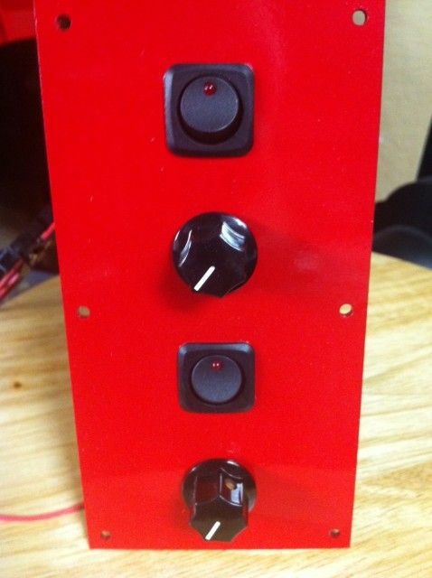
|
|
A little more progress. Got the control panel done - Hornady red. I also messed with the small rotor and baking pan. One thing I noticed is the flexible 8mm shaft adapter (posted earlier by someone) allows the pan to move too much, but I have a fix planned.
Sideways picture sitting on my garage floor: 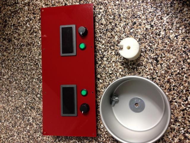
|
|
Originally Posted By RLR350:
A little more progress. Got the control panel done - Hornady red. I also messed with the small rotor and baking pan. One thing I noticed is the flexible 8mm shaft adapter (posted earlier by someone) allows the pan to move too much, but I have a fix planned. Sideways picture sitting on my garage floor: http://i369.photobucket.com/albums/oo134/rlr350/control_zps061be699.jpg I'm glad someone is getting close on this.... Its looking good RLR! Yeah those couplings are not really good for much except driving something that is supported on both sides. I am hoping to get some work done on mine today. I still need to get a coupler made and the case feeder done up... just not enough time to get everything done that i want to.... and now its getting to damn cold to work in the garage at night. Today and tomorrow is suppose to be nice but i want to hit the range sometime! |

|
Originally Posted By RLR350:
A little more progress. Got the control panel done - Hornady red. I also messed with the small rotor and baking pan. One thing I noticed is the flexible 8mm shaft adapter (posted earlier by someone) allows the pan to move too much, but I have a fix planned. I haven't ordered this, but I think it might work better that the flexible coupling: http://www.ebay.com/itm/181287796976?_trksid=p2055119.m1438.l2649&ssPageName=STRK%3AMEBIDX%3AIT I also think the 7mm side would be close enough for tapping the M8 threads for the cake pan screw. I'm going to try to make my own using 1" diameter aluminum bar. I have it cut and will be using a neighbor's drill press this afternoon. Machining the plastic case feeder might be interesting without a lathe, but I think I can get it close enough. |
|
Originally Posted By daeven:
I haven't ordered this, but I think it might work better that the flexible coupling: http://www.ebay.com/itm/181287796976?_trksid=p2055119.m1438.l2649&ssPageName=STRK%3AMEBIDX%3AIT I also think the 7mm side would be close enough for tapping the M8 threads for the cake pan screw. I'm going to try to make my own using 1" diameter aluminum bar. I have it cut and will be using a neighbor's drill press this afternoon. Machining the plastic case feeder might be interesting without a lathe, but I think I can get it close enough. Originally Posted By daeven:
Originally Posted By RLR350:
A little more progress. Got the control panel done - Hornady red. I also messed with the small rotor and baking pan. One thing I noticed is the flexible 8mm shaft adapter (posted earlier by someone) allows the pan to move too much, but I have a fix planned. I haven't ordered this, but I think it might work better that the flexible coupling: http://www.ebay.com/itm/181287796976?_trksid=p2055119.m1438.l2649&ssPageName=STRK%3AMEBIDX%3AIT I also think the 7mm side would be close enough for tapping the M8 threads for the cake pan screw. I'm going to try to make my own using 1" diameter aluminum bar. I have it cut and will be using a neighbor's drill press this afternoon. Machining the plastic case feeder might be interesting without a lathe, but I think I can get it close enough. I bought a 1.75" a 1' plastic rod from Grainger. I cut it in half for two six inch pieces. Jigged one piece up by screwing a 3/4 x 1" firing strip to both sides of it to act like a fence. Then I used a 1/4" straight bit on the router table set to the depth. I ran it against the fence twice, once each way it through one way to get a centered groove. I cut it to two inches on a power miter saw, then centered a small hole on the drill press - followed by a 1/4" hole. I used two 10-24 x 3/8" set screws centered in the groove to attach it to the arbor I figured out how to keep the flexible coupler straight by using a 5" square of lexan with a 13/16" hole in the center. It goes on the face of the unit with the coupler just showing through the hole - it acts a guide to keep the coupler from flexing, I'll show a picture when I get chance to take one. I worked on the frame for the box today.The side view looks odd in the picture. The back is vertical/straight, but the face tilts back, 6" from the back at the bottom and 4.5" from the back at the top.  
|
|
Originally Posted By RLR350:
I bought a 1.75" a 1' plastic rod from Grainger. I cut it in half for two six inch pieces. Jigged one piece up by screwing a 3/4 x 1" firing strip to both sides of it to act like a fence. Then I used a 1/4" straight bit on the router table set to the depth. I ran it against the fence twice, once each way it through one way to get a centered groove. I cut it to two inches on a power miter saw, then centered a small hole on the drill press - followed by a 1/4" hole. I used two 10-24 x 3/8" set screws centered in the groove to attach it to the arbor I figured out how to keep the flexible coupler straight by using a 5" square of lexan with a 13/16" hole in the center. It goes on the face of the unit with the coupler just showing through the hole - it acts a guide to keep the coupler from flexing, I'll show a picture when I get chance to take one. I worked on the frame for the box today.The side view looks odd in the picture. The back is vertical/straight, but the face tilts back, 6" from the back at the bottom and 4.5" from the back at the top. http://i369.photobucket.com/albums/oo134/rlr350/base_zpsee37f3af.jpg http://i369.photobucket.com/albums/oo134/rlr350/side_zpsbc318f79.jpg Originally Posted By RLR350:
Originally Posted By daeven:
Originally Posted By RLR350:
A little more progress. Got the control panel done - Hornady red. I also messed with the small rotor and baking pan. One thing I noticed is the flexible 8mm shaft adapter (posted earlier by someone) allows the pan to move too much, but I have a fix planned. I haven't ordered this, but I think it might work better that the flexible coupling: http://www.ebay.com/itm/181287796976?_trksid=p2055119.m1438.l2649&ssPageName=STRK%3AMEBIDX%3AIT I also think the 7mm side would be close enough for tapping the M8 threads for the cake pan screw. I'm going to try to make my own using 1" diameter aluminum bar. I have it cut and will be using a neighbor's drill press this afternoon. Machining the plastic case feeder might be interesting without a lathe, but I think I can get it close enough. I bought a 1.75" a 1' plastic rod from Grainger. I cut it in half for two six inch pieces. Jigged one piece up by screwing a 3/4 x 1" firing strip to both sides of it to act like a fence. Then I used a 1/4" straight bit on the router table set to the depth. I ran it against the fence twice, once each way it through one way to get a centered groove. I cut it to two inches on a power miter saw, then centered a small hole on the drill press - followed by a 1/4" hole. I used two 10-24 x 3/8" set screws centered in the groove to attach it to the arbor I figured out how to keep the flexible coupler straight by using a 5" square of lexan with a 13/16" hole in the center. It goes on the face of the unit with the coupler just showing through the hole - it acts a guide to keep the coupler from flexing, I'll show a picture when I get chance to take one. I worked on the frame for the box today.The side view looks odd in the picture. The back is vertical/straight, but the face tilts back, 6" from the back at the bottom and 4.5" from the back at the top. http://i369.photobucket.com/albums/oo134/rlr350/base_zpsee37f3af.jpg http://i369.photobucket.com/albums/oo134/rlr350/side_zpsbc318f79.jpg so what did you use for the distance between holes? x and y? |
|
Originally Posted By daeven:
I haven't ordered this, but I think it might work better that the flexible coupling: http://www.ebay.com/itm/181287796976?_trksid=p2055119.m1438.l2649&ssPageName=STRK%3AMEBIDX%3AIT I also think the 7mm side would be close enough for tapping the M8 threads for the cake pan screw. I'm going to try to make my own using 1" diameter aluminum bar. I have it cut and will be using a neighbor's drill press this afternoon. Machining the plastic case feeder might be interesting without a lathe, but I think I can get it close enough. Originally Posted By daeven:
Originally Posted By RLR350:
A little more progress. Got the control panel done - Hornady red. I also messed with the small rotor and baking pan. One thing I noticed is the flexible 8mm shaft adapter (posted earlier by someone) allows the pan to move too much, but I have a fix planned. I haven't ordered this, but I think it might work better that the flexible coupling: http://www.ebay.com/itm/181287796976?_trksid=p2055119.m1438.l2649&ssPageName=STRK%3AMEBIDX%3AIT I also think the 7mm side would be close enough for tapping the M8 threads for the cake pan screw. I'm going to try to make my own using 1" diameter aluminum bar. I have it cut and will be using a neighbor's drill press this afternoon. Machining the plastic case feeder might be interesting without a lathe, but I think I can get it close enough. 1" is a tad short on over all length IMO but it coulf be used. i have thought about using one but pretty much talked myself out of it. I plan on doing the same thing you are. |


|
Originally Posted By tstuart34:
so what did you use for the distance between holes? x and y? I used your drawing and estimated to come up with these measurements. Just note, I have not finished it for testing, but I am pretty sure it will work. Just a tip: Once you get the center point for your holes use the mark and draw a 2 1/4" diameter (set your compass at 1 1/8") circle around it. This will give you a reference for the motor holes so it is centered. Trying to do it after the 1 /38" hole is drilled is a pain. 
|
|
Originally Posted By RLR350:
I used your drawing and estimated to come up with these measurements. Just note, I have not finished it for testing, but I am pretty sure it will work. Just a tip: Once you get the center point for your holes use the mark and draw a 2 1/4" diameter (set your compass at 1 1/8") circle around it. This will give you a reference for the motor holes so it is centered. Trying to do it after the 1 /38" hole is drilled is a pain. http://i369.photobucket.com/albums/oo134/rlr350/Measurements_zps8d49a714.jpg Originally Posted By RLR350:
Originally Posted By tstuart34:
so what did you use for the distance between holes? x and y? I used your drawing and estimated to come up with these measurements. Just note, I have not finished it for testing, but I am pretty sure it will work. Just a tip: Once you get the center point for your holes use the mark and draw a 2 1/4" diameter (set your compass at 1 1/8") circle around it. This will give you a reference for the motor holes so it is centered. Trying to do it after the 1 /38" hole is drilled is a pain. http://i369.photobucket.com/albums/oo134/rlr350/Measurements_zps8d49a714.jpg Thanks i will look tomorrow at what i have drawn up. my frame is 12 x12 so i might be a bit different |
|
Originally Posted By tstuart34:
Thanks i will look tomorrow at what i have drawn up. my frame is 12 x12 so i might be a bit different Originally Posted By tstuart34:
Originally Posted By RLR350:
Originally Posted By tstuart34:
so what did you use for the distance between holes? x and y? I used your drawing and estimated to come up with these measurements. Just note, I have not finished it for testing, but I am pretty sure it will work. Just a tip: Once you get the center point for your holes use the mark and draw a 2 1/4" diameter (set your compass at 1 1/8") circle around it. This will give you a reference for the motor holes so it is centered. Trying to do it after the 1 /38" hole is drilled is a pain. http://i369.photobucket.com/albums/oo134/rlr350/Measurements_zps8d49a714.jpg Thanks i will look tomorrow at what i have drawn up. my frame is 12 x12 so i might be a bit different That's easy enough to convert. Just take the 1/2" off each measurement except the 5 1/4 one. 13" gave me 1" of board to the left of the 5" pan drum. So you would just end up with 1/2" to the left. Good luck. |
|
I came up with a nice trick to cut the reduced diameter portion of the case feeder if you don't have a lathe. A 1-1/8" or 1-1/4" hole saw can be used to cut into the end, then use a Dremel with a cut-off wheel lined up against duct tape to cut around the diameter. I notice this acetal/plastic material gives off eye-burning fumes when cutting, so use a fan and plenty of ventilation.
I was actually wondering if the reduced diameter section is even necessary since the mounting holes for the electric motor look to be further apart than the diameter of the case feeder. I think having the wall of the assembly acting as a back-stop to keep brass from sliding back will help prevent malfunctions, so I'm sticking with the same basic design. If I have the right bit, I'll be using a router with a jig to cut the channels for the brass into the length of the case feeder. |
|
Great going with your builds guys. Well done, should be proud with what you all accomplish. Remember you can build your build as simple and or as complex as you wish, after all its your build.
T stuart ill have the hole placements for you in the morning, found the box that had it in, also i have some extra bits to add to my build thanks to a mate of mine. Using some fittings. The bottle will be upright on the side of the build. Ill past some pics when i finish putting the fittings togeather. You guys should be proud :) Regards Skip |
|
Thanks Skip and Tstuart - I've built mine using your basic plans. It's not done yet, but the brass feeds reliably. I did find that the most difficult part was getting the brass to fall through the slot and stop in the correct orientation. The modification which allowed this to work cleanly was to cut the slot in the cake pan at an angle so the head of the brass starts to fall first. With a straight cut, the brass tended to get screwed up.
I used a wire hanger for the brass stop inside the pan. I bent it into shape, put it through a hole in the front panel, bent it in the back and secured it with a couple of screws. I still have to make the top panel and set up the torch mount, but the hard parts are done! 


|
|
Looks good daeven!
I did some more today. I added the reduced portion to the back of the feeder drum. I used the hole saw idea posted above, then turned my router table into a lathe of sorts to cut the excess away. Works well. And, since someone wanted more pictures in the thread, here is today's progress: First coat of paint. Back view of feeder hub. (That took a power miter saw, 1 3/8" hole saw, router/table with a 1/4" straight bit, 1/4" drill and press, 10-24 tap and a 1/2" spade bit in press to make)  
Back of front plate routed out so the motor mounts recess making it mount flat.  
Front plate and feeder hub testing. Lexan fix to keep the flexible coupler straight.  
|
|
Originally Posted By daeven:
Thanks Skip and Tstuart - I've built mine using your basic plans. It's not done yet, but the brass feeds reliably. I did find that the most difficult part was getting the brass to fall through the slot and stop in the correct orientation. The modification which allowed this to work cleanly was to cut the slot in the cake pan at an angle so the head of the brass starts to fall first. With a straight cut, the brass tended to get screwed up. I used a wire hanger for the brass stop inside the pan. I bent it into shape, put it through a hole in the front panel, bent it in the back and secured it with a couple of screws. I still have to make the top panel and set up the torch mount, but the hard parts are done! http://i1279.photobucket.com/albums/y521/daeven1/photo3_zps8a83ac1b.jpg http://i1279.photobucket.com/albums/y521/daeven1/photo4_zps653cfa7a.jpg http://i1279.photobucket.com/albums/y521/daeven1/photo1_zps0d798b4f.jpg Looks great! You and RLR are showing me up on my own project!  Saturday got tied up with lawn work (50+ deg In NEBRASKA) and a range visit. Saturday got tied up with lawn work (50+ deg In NEBRASKA) and a range visit.
I need to get the machine parts taken care of then it will be one big push to get it done. I think I pretty much have the prints all done up need to tweak a few things but I think everything will be good to go. |

|
Now that I see your stuff put together, it makes more sense. Basically, the cases feed from the flat funnel made from the two pieces of 90º angle) via the feed spool. Once fed, the case rotates in the flame while the cake pan turns it. When the cutout in the cake pan gets to where the case is, the case falls through, and is dropped to the other cake pan. Am I right?
I can see why you'd need two motors with two speed controls to make this work - at least to start out. Maybe later you can figure out how to use only one motor, but for now the gearing and connections would be kind of involved. Tweaking two different speed controls isn't a big deal when you're having to match the cake pan's speed (including the "drop through" time for the hot case to fall through) with the feed spool's speed. Very cool, guys! |
"--you can't conquer a free man; the most you can do is kill him."
Heinlein
NRA Life Member
Glock Certified Armorer
Certified AR15 Armorer
Certified M1911 Armorer
Heinlein
NRA Life Member
Glock Certified Armorer
Certified AR15 Armorer
Certified M1911 Armorer
|
Originally Posted By GHPorter:
Now that I see your stuff put together, it makes more sense. Basically, the cases feed from the flat funnel made from the two pieces of 90º angle) via the feed spool. Once fed, the case rotates in the flame while the cake pan turns it. When the cutout in the cake pan gets to where the case is, the case falls through, and is dropped to the other cake pan. Am I right? I can see why you'd need two motors with two speed controls to make this work - at least to start out. Maybe later you can figure out how to use only one motor, but for now the gearing and connections would be kind of involved. Tweaking two different speed controls isn't a big deal when you're having to match the cake pan's speed (including the "drop through" time for the hot case to fall through) with the feed spool's speed. Very cool, guys! That is exactly right! I have a single motor plan in my head but im to lazy to draw it up at this point in time. Maybr in the future if i get tired of messing with two speed pots. But the way i havr in mind will coat more them a controler and motor would so thats turing me off of it right now. |
|
The funnel was put on today. Made of 1" x 2" angle aluminum. Each side is 6", with a hack saw slice in the 1" side at 3", then bent to the correct angle in a bench vise. Tested and seems to work fine.
Any tips on cutting the pans down to size? I plan to use one that will do both 223 and 300, then one for 308. I haven't given it any thought, but that is the next step, along with the opening. 
|
|
Dremel with a cutoff wheel. mark a circle around the circumference, then cut away.
Tin snips will disort the sides, and you need to get past the lip. A bandsaw may bind in the cut and get the operator hurt. A saber saw with a metal cutting blade might work, but you'll have to have the pan clamped tight, and good control of the saw. |
Just remember, it was Ping! before it was Pew-Pew-Pew....Harv24
|
Originally Posted By RLR350:
Any tips on cutting the pans down to size? I plan to use one that will do both 223 and 300, then one for 308. I haven't given it any thought, but that is the next step, along with the opening. http://i369.photobucket.com/albums/oo134/rlr350/front4_zps922c79e5.jpg Looks great so far. I think I'd use a band clamp (home depot) or bunch of big rubber bands to mount a Dremel vertical, say to a table leg or something, such that it can be adjusted up or down. Then place the pans upside down on the floor and rotate the pan into the dremel metal cut-off blade. That way you'd cut nice and even. 
Three questions for ya:
 ) )
|
|
I think I'd use a band clamp (home depot) or bunch of big rubber bands to mount a Dremel vertical, say to a table leg or something, such that it can be adjusted up or down. Then place the pans upside down on the floor and rotate the pan into the dremel metal cut-off blade. That way you'd cut nice and even.
Nice idea. I just tried this using a ratcheting tie-down strap wrapped around a workbench leg and a Dremel a couple of times. Perfect clean cut! Here are some more pics of my project now that I added the control panel. I still need to get a torch holder, and I haven't finished the new pan, but you can see it here catching the brass. 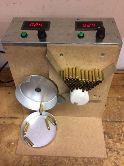


|
|
Originally Posted By RLR350:
The funnel was put on today. Made of 1" x 2" angle aluminum. Each side is 6", with a hack saw slice in the 1" side at 3", then bent to the correct angle in a bench vise. Tested and seems to work fine. Any tips on cutting the pans down to size? I plan to use one that will do both 223 and 300, then one for 308. I haven't given it any thought, but that is the next step, along with the opening. http://i369.photobucket.com/albums/oo134/rlr350/front4_zps922c79e5.jpg From the way I see it, you don't have to cut through the lip of the pan. Leaving the rolled lip will leave the cake pan stronger than just cutting a slice out of the whole side. If your pan is tall enough for .308 cases, cut a rectangular window between the bottom and lip of the pan. I agree that a Dremel with a cutoff wheel is the way to go, but it shouldn't be any harder to cut out a window than a slice. |
"--you can't conquer a free man; the most you can do is kill him."
Heinlein
NRA Life Member
Glock Certified Armorer
Certified AR15 Armorer
Certified M1911 Armorer
Heinlein
NRA Life Member
Glock Certified Armorer
Certified AR15 Armorer
Certified M1911 Armorer
|
Originally Posted By GHPorter:
From the way I see it, you don't have to cut through the lip of the pan. Leaving the rolled lip will leave the cake pan stronger than just cutting a slice out of the whole side. If your pan is tall enough for .308 cases, cut a rectangular window between the bottom and lip of the pan. I agree that a Dremel with a cutoff wheel is the way to go, but it shouldn't be any harder to cut out a window than a slice. Originally Posted By GHPorter:
Originally Posted By RLR350:
The funnel was put on today. Made of 1" x 2" angle aluminum. Each side is 6", with a hack saw slice in the 1" side at 3", then bent to the correct angle in a bench vise. Tested and seems to work fine. Any tips on cutting the pans down to size? I plan to use one that will do both 223 and 300, then one for 308. I haven't given it any thought, but that is the next step, along with the opening. http://i369.photobucket.com/albums/oo134/rlr350/front4_zps922c79e5.jpg From the way I see it, you don't have to cut through the lip of the pan. Leaving the rolled lip will leave the cake pan stronger than just cutting a slice out of the whole side. If your pan is tall enough for .308 cases, cut a rectangular window between the bottom and lip of the pan. I agree that a Dremel with a cutoff wheel is the way to go, but it shouldn't be any harder to cut out a window than a slice. That's exactly what I was thinking. I have parts ordered, but waiting on the slow boat from China. |
|
Originally Posted By Kvanderploeg:
That's exactly what I was thinking. I have parts ordered, but waiting on the slow boat from China. Originally Posted By Kvanderploeg:
Originally Posted By GHPorter:
Originally Posted By RLR350:
The funnel was put on today. Made of 1" x 2" angle aluminum. Each side is 6", with a hack saw slice in the 1" side at 3", then bent to the correct angle in a bench vise. Tested and seems to work fine. Any tips on cutting the pans down to size? I plan to use one that will do both 223 and 300, then one for 308. I haven't given it any thought, but that is the next step, along with the opening. http://i369.photobucket.com/albums/oo134/rlr350/front4_zps922c79e5.jpg From the way I see it, you don't have to cut through the lip of the pan. Leaving the rolled lip will leave the cake pan stronger than just cutting a slice out of the whole side. If your pan is tall enough for .308 cases, cut a rectangular window between the bottom and lip of the pan. I agree that a Dremel with a cutoff wheel is the way to go, but it shouldn't be any harder to cut out a window than a slice. That's exactly what I was thinking. I have parts ordered, but waiting on the slow boat from China. I think I understand what you mean, but it won't work. The neck of the case has to stick out beyond the pan to catch the flame. The pan's entire depth has to be changed. The same depth should work for 300 and 223. Or a deeper pan might work for 223 and 308. The difference in 300 and 308 is too great (I haven't tested it yet, but will.). Cutting a window would work for the drop part, but not the flame part - unless I'm not getting what you mean. The strength of the pan without the lip is not an issue. The pan is just spinning with a single case so it's not under any pressure or load really. |
DIY Annealing Machine (Page 3 of 17)
Armory Sponsor