


Armory Sponsor


Posted: 1/15/2019 11:57:51 PM EDT
|
Boresighting and Collimating Night Vision Devices (at home with basic parts)
One of the topics that I find is often misunderstood is boresighting. It's the reason that Clip On's shoot straight, and can mean the difference between hitting a target and missing it at 10 yards when shooting instinctively. But it's really easy to do, requires only a few common parts most people on this forum should have laying around, and can be set up as a re-usable system that you can pull out when needed, and you can use the parts for their normal application most of the time when not boresighting something. This method is the one I said I'd write up about last year... So today, let's look at boresighting, collimation, optical alignment, repeatability and whether or not it's possible to boresight a PVS-14. I promised I'd set this up, and I have, but it took me a little while as I had to get some other projects out of the way first. Boresighting is a simple concept. If you have a boresighted device, it's been set more-or-less so that it doesn't cause an angular divergence to the path of light. If you boresight a night vision device, then when it's placed in front of, say, a riflescope, then the POI doesn't shift. I won't go into explaining much more than this, because I've already written about it in a past article. Instead, I'm going to talk about how to check the angular divergence of a NOD and what you can do about it. Why might you want to do this? Well, if you have a clip-on, and a high-accuracy optical alignment tool to check it, you can verify how much it moves the POI in practice, or how resistant it is to lateral movement and other factors that can introduce errors. And if you have a set of binoculars, you can measure the divergence and perform collimation not only in one axis, but in two, identifying where the optimal two points of convergence are one step beyond a basic collimation. Yet there's a third option too, and one that isn't well understood. If you have a means to accurately measure optical divergence, how does it help if you only have, say, a PVS-14? You might think that if you boresight a PVS-14, you can use it as a clip-on, and sure, you can, but that's only one practical application and PVS-14's not boresight all that well. More importantly, you can boresight it so that your eyes can converge with using an un-aided eye and, if you happen to be lucky, you can zero-boresight it so that it's not only a basic clip-on, but more importantly, can also be used for instinctive shooting. The problem with using nods is that their optics aren't axially aligned. If you're looking at a target and you slip a NOD between you and the target, the target appears to move. This means your perception about where you think a target is, is greatly distorted. So let's jump straight into how you make such a test device... After all, these things cost easily five figures don't they. But I watched pretty much every episode of the original McGyver series, and I'm pretty sure most of you have this stuff lying around the house and you could knock up a calibration stick in a half-hour or so. What you're going to need is a NV compatible red-dot sight and a telescopic sight, or two telescopic sights with different, illuminated, reticles in which you modify the brightness of the both so that you can adjust them for roughly equal brightness after one is amplified. OK, enough waffling, let's start building. This first step is simple, but getting the alignment correct is critical, even though there's plenty of room to correct errors, so as long as you align the parts by hand as closely as you can, you should be able to use the turrets to calibrate this instrument. Take a piece of wood, about 2.5ft to 1 yard long. I used a bit of 3"x1" pine. Take a couple of Picatinny rails and screw them into the wood at either end, so that when you mount a telescopic sight at one end, it can look at the red-dot sight at the other with a gap larger than the optics you want to measure in the middle. Use spacers so that both centers of the optics are at the same height and then screw the pieces together... Like this. 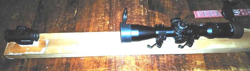
I 3D printed those picatinny rails, so it's isn't complicated, and you don't need quality materials, but you MUST use a front-scope that has a fixed parallax free distance of at least 100m. Forget cheap chinese knockoffs this time, unless you get lucky. Make sure you have a 100m parallax free front scope. Like this nice Aimpoint.. The rear sight should also be parallax free at the same distance eg, 100m. Don't mix 40m and 100m units, but it's OK to mix adjustable-parallax units, since you can set them. Step 2. Congratulations. You've now finished you... No, wait a bit. We need to calibrate this instrument. Turn on the front scope ( in this case, the aimpoint. ) Turn on the back scope reticle. Look through it. See the front scope reticle? Twiddle the turrets until it's in the middle of the back-scope reticle. Like Darth Vader did with Luke's X-wing over the Death Star canyon. Now it should look something like this; (red is aimpoint, green is dayscope) 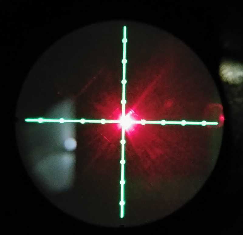
Congratulations, you've really finished now. Sure, go ahead and wiggle stuff to convince yourself it's solid. You may be surprised at how much you can actually bend the wood with your hands. Mine moves all over the place, but it always returns to zero when I remove the stress. If you want a better system, then you can use metal rails and a piece of 1" square section metal tube instead of a piece of wood, and maybe even use a variable 8-40x magnification scope for high accuracy if you're testing clip-on NVDs, but this is how you set up this instrument. OK, now you're complete, it probably took you longer to find all the parts than it did to assemble them. You built an optical path calibration instrument McGyver style, and it's probably more accurate than one you can purchase for under $10,000, assuming you used all quality parts. Have a play, maybe take the day scope off and put it back on a few times, to convince yourself it holds zero. It should. The only really critical part, in terms of integrity, is the front mount that holds the aimpoint in my case. That needs to be solid, and well fixed to the beam. As a first test then, try removing the rear telescopic sight, and re-installing it, then check if it is still holding zero. If it doesn't, or if the red dot moves around a LOT while moving your head from side to side, then your dayscope or red-dot sight is problematic... That knowledge in and of itself is worth the price of admission here. In a good scope, there won't be any movement. In my case, it's solid at 12x but at the lower 3x, I found my dayscope has a parallax issue, which means I can only shoot accurately at maximum magnification. Well, it's an Arctic-Fox scope, so it's kind of a budget scope to begin with, but that kind of information is extremely challenging to figure out any other way. One I hit about 8x it's fine, but any lower than that and the accuracy of my scope is lost so quickly that just a change in shooting position would make a difference in POI with a ratio of about 2cm in 10m. Or 20cm, nearly a foot, over 100m. This was quickly measured with this tool. So now we have two sights in perfect co-witness, looking at the same, well, the target is irrelevant, because one scope is looking at the other, and they are both aligned with a virtual space about 100m away. You could take it outside and still see both sight reticles and a target since the red-dot sight will probably be mostly invisible to the dayscope being a small aimpoint in this case, but that's OK. Now we're set, our instrument is calibrated and we have an accurate way of measuring changes in angular deflection smaller than 0.1 diopters. Maybe even to less than 0.01 diopters if you have a high magnification dayscope. Going outside to test, BTW, is a good way to calibrate the illuminated reticle. Mark out a piece of wood, or paper, with say 1" thick lines, and put it out at 100 yds distance and look at it through the scope. Now you know how much POI variation occurs at 100 yds when you move a mildot on the reticle, and if you want, you might also want to check if you have a real mildot reticle, since a single mildot is supposed to be about 3.6" @ 100yds, and not all mildots are created equal. So, what do we measure with this new tool with relation to the PVS-14 or Clip-On NVDs? If you have a clip-on, and you made the space big enough, now is a good time to see how accurately it was boresighted at the factory. Stick it in the middle, just sit it there if you like, and if the red dot isn't perfectly in the center (note, it's a green or white dot now, since it's going through an image intensifier), then you can tell how much your POI just moved, all without firing a single shot. Are you happy with your clip-on? Do you want to correct by eye or take it back to the factory to be rebuilt? Go ahead. Now you have proof that it's moving the POI, and you know by exactly how much. Try twisting the clip-on left to right a bit, so it's not aligned with the optical axis anymore, but you can still see the dot. Does the dot move? It probably will move a bit. This is off-axis error induced by imperfect magnification, tube distortion and lens aberration. Since you never can be certain your clip-on is perfect, this difference should never exceed 2MOA, or about 2" at 100 yds. I know it's intuitive that twisting it should introduce POI change, but the truth is that you shouldn't introduce any POI change at all, even when a few degrees off-axis. Any movement in POI while you can still see the target is internal error specific to your Clip-On and is likely due to imperfections within the tube rather than the optics. Want to collimate a NOD? Stick it in there. Here's the first result I got when I put my PVS-14 in the middle. 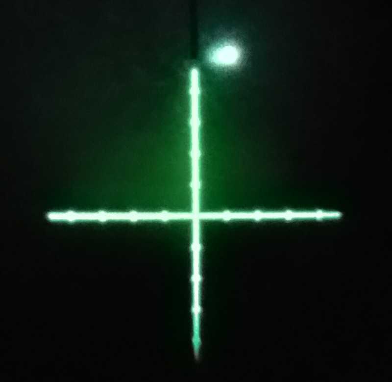
I didn't do anything too complicated. I just put the NOD on a book sitting in the middle... You'll notice when you do this, it doesn't need to be too accurately placed. If the dot from the NOD isn't focussed, then turn the end focus knob to make it focussed. It really is that simple - in fact, wiggle the NOD around while watching the dot, and you'll find it doesn't move much even when the NOD is wiggled around, though you might want to mask off the outer glass of the ocular by making a plate with a 10mm hole and putting this over the ocular first so that aberration in the ocular doesn't make the dot too blurry ( the above is taken without the benefit of such, but your mileage may vary here ). 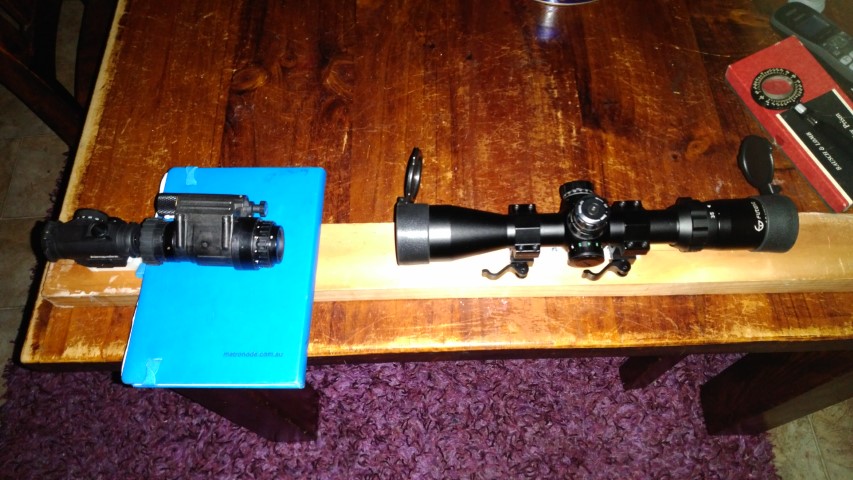
This is my first result. That dot? That's how much the POI moved when I used my PVS-14 as a clip-on. It's all Milspec too, and a much tigher Milspec than even US aviation glasses... As for PVS-14's? They can be out by more than three times this much... Think you're going to hit anything? If you are wearing this nod, you might not even be able to hit someone at 10m instinctively. That's a BIG induced error. OK, so what can we do about this Worse, you can imagine if your other NOD in bino's using PVS-14's is out by this much, you've going to end up cock-eyed. Here's where Milspec for ANVIS oculars comes in. If you rotate the rear ocular lens housing, you can correct by rotating the POI in a 2.5 to 3 prism-diopter circle. 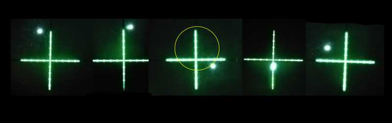
As this POI moves, when the ocular is rotated 360 degrees, it traces out a circle kind of like the one I drew in yellow in the center. These are all the possible angular errors you can configure your PVS-14 to have. Where that circle is from scope to scope will vary a lot, and I think these Mildots are a lot further apart than normal ones, so the error is pretty big, but generally you will find that the size of the circle itself is consistent from monocular to monocular as it's built into the ocular lens. In my case, I chose the fourth setting, which is about 2" to 3" low at 10m, but is centered. This means I lose some elevation when using my NOD, but things are pretty much where I expect them to be. I could also place it on the horizontal line, so that both eyes are at the same height which is definitely recommented, but it's pretty good for my applications at the bottom, and the variation isn't enough to cause me too many visual problems given the amount of time I spend at night with NODs on. If it was an aviation system, you'd put them both on the same horizontal plane, but close to the middle, or as close together on the same side as possible. If it was binocular PVS-14's you'd try to choose the two points where the circles intersected ( optimal ) or as close as possible, and if they were too far apart, don't even try to make binoculars out of them. It will mess with your head. Of course, the PVS-14 should be installed "right way up" when you collimate it like this - that is, whichever way is up when you're head mounting it. The PVS-14 was never intended to be collimated, but that doesn't mean that you won't benefit from understanding how this process works and optimising where you lock down your ocular rotation. There's one other factor Because many PVS-14 ocular lenses distort the image significantly at the edge of the FOV, especially when viewed from a distance or with a large aperture, the aperture of the PVS-14 ocular lens should be limited when you do this, to about 10mm, to correct for these aberration issues. Otherwise error will occur depending on where you're looking from. Better still, use a camera behind the dayscope. This will allow consistency between all measurements. In the above images, I didn't correct for the aberration, so if you were to center them on each other and find a perfect circle, you'd find a slight error in the outcome. So now you've made it, just how valuable is a tool like this to you? There's not an armourer in the world that couldn't use one of these. Keep it in the armoury and test each clip-on before it goes out even whack the NOD being tested a few times with a soft rubber mallet beforehand to ensure it holds its zero. Test NODs for both collimation and that they are within appropriate off-axis specifications in a heartbeat. You don't even need to set it up just calibrate the zero, like you did the first time, before use. This can even be used to check dayscope mounts and holding zero when repeatedly removed and installed. As such, this is a great tool for use, is easy to set up and use, and you don't even need to dedicated a scope to it Just dismount the scopes for storage, and when you need it, you can set it up and calibrate it in less than a minute. It doesn't get any better than that. I did modify mine slightly after this, and included a PVS-14 mount, since I don't have any clipons that I need to test at the moment. This lets me quickly mount and check a PVS-14 for collimation. 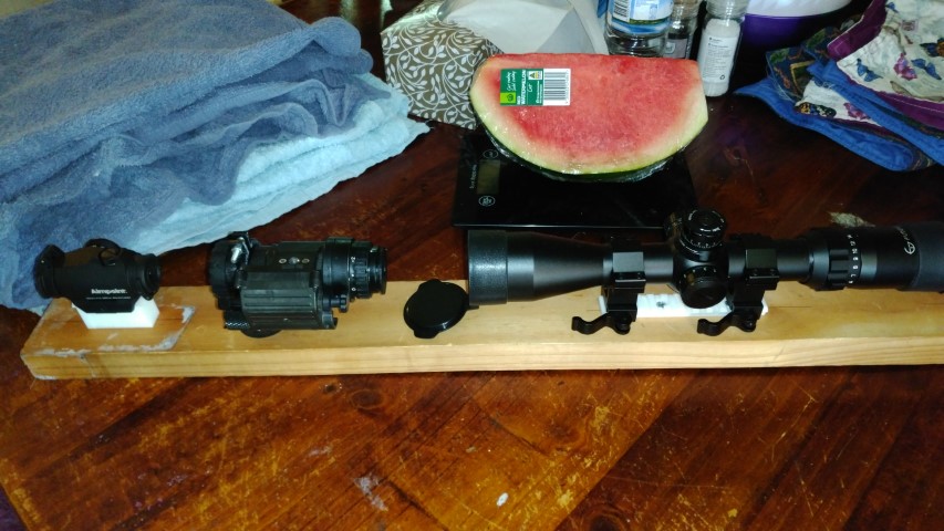
And yeah, that watermelon is my self-assigned reward for McGyvering this stuff out of things I found in the kitchen since I found that too, so I'll eat it now. If you make one, and you do a better job that I did, which I'm pretty sure some of you will, please post pics here. If you find something interesting, or your clipon is really crappy, let us know. If you intend to check Clip-Ons from the start, then make sure to leave enough room between the scopes for the test device to fit, and use a high magnification scope, or better still a variable magnification scope with high magnification settings. Also, if you are using a variable magnification scope, make sure it doesn't lose POI with repeated changes in the magnification level. How do you do that? Well, just do it and observe. Another valuable capability of this jig is, as was mentioned earlier, just testing dayscope. Come to think of it, it's probably more valuable in that respect than any other tool you have in your shooting toolbag. So tell me what you found, what you were happy with and what you were disappointed with. And especially, if you have a commercial clip-on and a decent (eg, 40x magnification) scope to test it's collimation, let us know how far out it was when you tested it. David. |
|
Very interesting David. Wouldn't using a good quality AR rifle with a rail that is aligned properly with the upper and than placed in a vice accomplish the same thing as the pine board with pic rails attached? Now forgive me as I am not a tech guy so maybe I am missing something or not understanding you. How does rotating the rear ocular lens of the PVS14 to move the front scope dot to where you want do anything long term. Once you go to actually use the unit you will have to adjust the rear ocular to work with your individual eyesight again and doesn't that negate the alignment that was done. |
|
Quoted:
Very interesting David. Wouldn't using a good quality AR rifle with a rail that is aligned properly with the upper and than placed in a vice accomplish the same thing as the pine board with pic rails attached? Now forgive me as I am not a tech guy so ,maybe I am missing something or not understanding you. How does rotating the rear ocular lens of the PVS14 to move the front scope dot to where you want it does anything long term. Once you go to actually use the unit you will have to adjust the rear ocular to work with your individual eyesight again and doesn't that negate the alignment that was done. |
|
Quoted: When you rotate the whole ocular lens, it changes the center axis as the rear ocular lens is offset. Simply adjusting the rear ocular diopter adjustment is not what he is describing-you would rotate the entire lens cell then lock it with the locking ring. |
|
Quoted:
Is this not how its done? could you expand on your googly eyes. Quoted:
Quoted:
 Anyway, this method lets you check collimation. It doesn't allow dual-collimation automatically as you can't see both NODs at the same time. You can still collimate them one at a time, but setting them on the same horizontal plane, or you can try to collimate both to the same error. Same horizontal plane is easy- Just stick them both on the horizontal line, as close to each other as you can. If you want to collimate both to the same error though then you need to move to where the circles overlap. The full process is first set your zero diopter position. Ideal is to focus a camera at infinity, and then mask off all but the center 10mm of the ocular and then, with the pinhole cap on and sharp front focus, adjust the rear focus until the picture on the camera comes into sharp focus. This sets the zero diopter position to the same relaxed position as the human eye. Then work our where your circles that rotating the ocular exist on the reticle, and roughly where they cross over, and what part of the circle that was. Then collimate one NOD to that position and remember which direction the tangent to that position was in (eg, 45 degree angle climbing left ). Adjust the center crosshairs turrets on the scope to bring that position to the middle. Switch in the other NOD and try to adjust the ocular to the same center position that the crosshairs indicate. If it's a bit high, low, left or right, then adjust it so it's where the circle line would cross, then again, recenter the crosshairs on the new position and switch back to the first monocular and repeat. Have them in the bridge while doing this ( important ) and eventually, neither monocular will cause a deviation of the dot from the center of the crosshairs. At this point, both are shifting the optical axis, but are doing it by exactly the same amount. ( Slightly more advanced than collimating, not as good as boresighting ). At this point, you won't be looking straight at the target object, but at least both monoculars are parallel. You can recenter the kit and measure how far both are off now if you like, just for informational purposes ( or if you shoot instinctively and want to correct by eye ) but at this point your home-brew binocs should be pretty well collimated. David. |
|
Quoted: You and me both. That wall of text just fell on my brain and killed it. By attaching a riflescope with an adjustable reference point in the form of a graph-style reticle to a fixed rail, and installing co-witness a suitable second reticle in front, with parallax at 100m distance, for reasons of a virtual point of aim, it is possible to confirm optical path deviation for the purpose of boresighting, collimation and equipment testing of Clip-ons, Nods and Dual-NOD setups. And then you can eat watermelon. David. |
|
Quoted:
Hey david, is there adjustment designed into the objective lens side too? Just thinking about how the threads on the cell start into the housing and one of my 14's is definitely a little Even if it does have issues, you can always set it up for infinity since that's where you'll use it most of the time, and it should still remain consistent. So it's not so much of a problem with the front lens since it will usually be in the same position most of the time. I think the rear focus is something like quarter of a marking difference per rotation of the lens, so it's not a big deal there, but at the front lens, it makes a huge difference - Based on travel per turn, the front lens moves way further for a single turn than the rear lens housing( which moves about 0.3mm or something like that per half turn ). I should mention that once you set the 0 diopter position, you should only rotate the entire assembly about a half turn either way, rather than just going around and around until you're in the right spot. David |
|
I tried this with a old scope and a Aimpoint M2. I was kinda hoping that I would be able to get a bullseye with the PVS-14 in the middle, but unfortunately rotating the ocular lens also rotated the M2 dot perfectly around the center of the crosshairs. So basically the POI will be about 2 feet off at 50 yards. I was hoping the rotation would be offset enough that I could hit close to the center of the crosshairs, but it was literally a perfect circle around it. Scope crosshairs Attached File Crosshairs with M2 dot centered perfectly Attached File A couple shots with the PVS-14 in between Attached File Attached File |
|
Quoted:
I was hoping the rotation would be offset enough that I could hit close to the center of the crosshairs, but it was literally a perfect circle around it. You could try an uncorrected lens and see if that improves things. I get some results like that with the ether lenses. If you find your nods are either low or high though, when mounted, you can correct for that much to reduce neck strain a little. David. |
Armory Sponsor