


Armory Sponsor


Posted: 12/8/2013 8:59:51 AM EDT
[Last Edit: PR361][Edited]
|
I like to tuck away dreams in the hope that " One Day", when I'm retired and the Kids are gone,
I'll have unlimited time tinker with all this stuff. For those of you like me, or those of you who actually HAVE the time to take it on; a cool little project. AR Lower Prints in PDF I'm sure it's been seen before, but new to me and probably others. ETA: Found it Here, there's some good photos of the finished product. 
|
The nice part about being a pessimist is that you are constantly being either proven right or pleasantly surprised.
George Will
Eagle Scout
Vet
NRA Life Member
George Will
Eagle Scout
Vet
NRA Life Member


|
Originally Posted By _DR:
I don't have the machinining skills to make parts that look that good. Pretty cool though. Read through this, then tell me you can't make that lower receiver - http://americanlongrifles.org/forum/index.php?topic=25540.0 If that isn't convincing, then look at runastav's other projects. |
It is not easy to explain Liberty to those that are not familiar with Liberty. Kevin Jamison, on explaining firearm regulation to a Massachusetts lawyer. Jeff City, Mo 18 Apr 13.

|
Originally Posted By PR361: I like to tuck away dreams in the hope that " One Day", when I'm retired and the Kids are gone, I'll have unlimited time tinker with all this stuff. For those of you like me, or those of you who actually HAVE the time to take it on; a cool little project. AR Lower Prints in PDF I'm sure it's been seen before, but new to me and probably others. ETA: Found it Here, there's some good photos of the finished product. |
Now that's how a country man do!

|
Originally Posted By PR361:
I like to tuck away dreams in the hope that " One Day", when I'm retired and the Kids are gone, I'll have unlimited time tinker with all this stuff. For those of you like me, or those of you who actually HAVE the time to take it on; a cool little project. AR Lower Prints in PDF I'm sure it's been seen before, but new to me and probably others. ETA: Found it Here, there's some good photos of the finished product. Thanks for posting--I'm gonna make one. |
Sorry, in America you are guilty until proven innocent.
-- godzillamax
-- godzillamax

| Someone needs to design this out of stacked sheets of steel that can be water jetted or lasered out then riveted or use button head hex screws so the thick machinings are minimized. Maybe to the point that only the buffer tube/receiver extension needs threading. |
Omnis vestri substructio es servus ad Chuck Norris.

|
Originally Posted By AJ_Dual:
Someone needs to design this out of stacked sheets of steel that can be water jetted or lasered out then riveted or use button head hex screws so the thick machinings are minimized. Maybe to the point that only the buffer tube/receiver extension needs threading. Does the buffer tuber really need to be installed in a threaded hole? What would you do if you needed a gun now and the only thing holding up the show was a threaded joint? There is an earlier AR lower made up from flat sheet. The catch is that there are a zillion more fasteners. Another option is welding of some subassemblies, maybe even bonding if surface prep is done with some discipline. |
It is not easy to explain Liberty to those that are not familiar with Liberty. Kevin Jamison, on explaining firearm regulation to a Massachusetts lawyer. Jeff City, Mo 18 Apr 13.

|
Originally Posted By AeroE: Does the buffer tuber really need to be installed in a threaded hole? What would you do if you needed a gun now and the only thing holding up the show was a threaded joint? There is an earlier AR lower made up from flat sheet. The catch is that there are a zillion more fasteners. Another option is welding of some subassemblies, maybe even bonding if surface prep is done with some discipline. Originally Posted By AeroE: Originally Posted By AJ_Dual: Someone needs to design this out of stacked sheets of steel that can be water jetted or lasered out then riveted or use button head hex screws so the thick machinings are minimized. Maybe to the point that only the buffer tube/receiver extension needs threading. Does the buffer tuber really need to be installed in a threaded hole? What would you do if you needed a gun now and the only thing holding up the show was a threaded joint? There is an earlier AR lower made up from flat sheet. The catch is that there are a zillion more fasteners. Another option is welding of some subassemblies, maybe even bonding if surface prep is done with some discipline. On a rifle buffer tube I would think a person could use the flange on the tube for mounting. The stock would need modified, but in a pinch it could be made to work. Ugly as sin, but work. A part could be made that presses against the buffer tube flange, and the part could be held in place with screws. Maybe a notch cut in the flange and that fits around a pin in the lower to keep the tube from rotating.  |
AR-10 is my arch enemy
"I'll agree that turtles have feelings if you agree there's a small chance that he enjoyed flying." Brownie55
"I'll agree that turtles have feelings if you agree there's a small chance that he enjoyed flying." Brownie55
|
There's a simpler method.
Anyway, I found an error in those drawings today. It's not serious, but would be annoying and would require the part to be modified or possibly made over, I'll have to check it closer. In any case, the trigger guard does not fit the pistol grip detail. The profile along the 30 degree angle many need to be revised, too. There is one feature I would change during machining the parts; there are some inside corners that need a fillet to reduce the stress concentration in the corners. That will require a chamfer or radius on the edge of the mating parts, but the cost of the materials and time needed to layout and machine the parts more than justifies doing the job right. I expect I'll find a couple more. |
It is not easy to explain Liberty to those that are not familiar with Liberty. Kevin Jamison, on explaining firearm regulation to a Massachusetts lawyer. Jeff City, Mo 18 Apr 13.
|
Originally Posted By substandard:
What are you thinking? Originally Posted By substandard:
Originally Posted By AeroE:
There's a simpler method. What are you thinking? Bond the buffer tube into the receiver. Many receivers from 80% castings have been assembled this way. It's expedient, not perfect. This has caused me to revisit the idea of a simple means to secure the tube besides bonding it into the receiver. In the mean time, there's a dimension missing that I can't uncover or derive. On page 40, the depth of the 0.250 wide slot is missing. It might be right under my nose, but I've looked long enough and can't find a hint. The details really need to be re-dimensioned to cut down on the time to sort 'em out. The number of pages could be cut way down, too. I wish I had a solid model of a pistol grip to check a couple of other details. |
It is not easy to explain Liberty to those that are not familiar with Liberty. Kevin Jamison, on explaining firearm regulation to a Massachusetts lawyer. Jeff City, Mo 18 Apr 13.
|
Originally Posted By AeroE:
Bond the buffer tube into the receiver. Many receivers from 80% castings have been assembled this way. It's expedient, not perfect. This has caused me to revisit the idea of a simple means to secure the tube besides bonding it into the receiver. In the mean time, there's a dimension missing that I can't uncover or derive. On page 40, the depth of the 0.250 wide slot is missing. It might be right under my nose, but I've looked long enough and can't find a hint. The details really need to be re-dimensioned to cut down on the time to sort 'em out. The number of pages could be cut way down, too. I wish I had a solid model of a pistol grip to check a couple of other details. Originally Posted By AeroE:
Originally Posted By substandard:
Originally Posted By AeroE:
There's a simpler method. What are you thinking? Bond the buffer tube into the receiver. Many receivers from 80% castings have been assembled this way. It's expedient, not perfect. This has caused me to revisit the idea of a simple means to secure the tube besides bonding it into the receiver. In the mean time, there's a dimension missing that I can't uncover or derive. On page 40, the depth of the 0.250 wide slot is missing. It might be right under my nose, but I've looked long enough and can't find a hint. The details really need to be re-dimensioned to cut down on the time to sort 'em out. The number of pages could be cut way down, too. I wish I had a solid model of a pistol grip to check a couple of other details. 0.1040 in. |
Sorry, in America you are guilty until proven innocent.
-- godzillamax
-- godzillamax
|
The depth of the cut is not 0.104 inches. Look to the right of that dimension, at the 0.250 wide slot cut part depth into the upstanding flange; the depth is less than 0.104 inches.
|
It is not easy to explain Liberty to those that are not familiar with Liberty. Kevin Jamison, on explaining firearm regulation to a Massachusetts lawyer. Jeff City, Mo 18 Apr 13.
|
Originally Posted By AeroE:
The depth of the cut is not 0.104 inches. Look to the right of that dimension, at the 0.250 wide slot cut part depth into the upstanding flange; the depth is less than 0.104 inches. Ok, that's driving me nuts now. Since that cut is on the left side and looks like it is for the mag release bar, i'm thinking it must be 0.0690 as shown on page 6. |
Sorry, in America you are guilty until proven innocent.
-- godzillamax
-- godzillamax


There's an interference at the upper surface of the pistol grip, otherwise one detail I thought was a problem looks okay but will require hand fitting; that's okay, it's not the only location that will probably need a tweak. There's no guarantee that the pistol grip model is correct, but I have to accept what I was given for now. I suppose I should measure the interference ... It's 0.164 inches at the upper surface, but it's also too wide and interferes at the front edge of the cutout, too. |
It is not easy to explain Liberty to those that are not familiar with Liberty. Kevin Jamison, on explaining firearm regulation to a Massachusetts lawyer. Jeff City, Mo 18 Apr 13.
|
Originally Posted By AeroE:
http://www.ar15.com/media/viewFile.html?i=59229 There's an interference at the upper surface of the pistol grip, otherwise one detail I thought was a problem looks okay but will require hand fitting; that's okay, it's not the only location that will probably need a tweak. There's no guarantee that the pistol grip model is correct, but I have to accept what I was given for now. I suppose I should measure the interference ... It's 0.164 inches at the upper surface, but it's also too wide and interferes at the front edge of the cutout, too. Nice work!!!! 
|
Sorry, in America you are guilty until proven innocent.
-- godzillamax
-- godzillamax
|
Originally Posted By AJ_Dual:
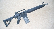
Someone needs to design this out of stacked sheets of steel that can be water jetted or lasered out then riveted or use button head hex screws so the thick machinings are minimized. Maybe to the point that only the buffer tube/receiver extension needs threading. Jack Squat's Flat Spots does a weldable kit. You may be able to modify it to be riveted or screwed together. |
|
Originally Posted By AeroE:
Read through this, then tell me you can't make that lower receiver - http://americanlongrifles.org/forum/index.php?topic=25540.0 If that isn't convincing, then look at runastav's other projects. Originally Posted By AeroE:
Originally Posted By _DR:
I don't have the machinining skills to make parts that look that good. Pretty cool though. Read through this, then tell me you can't make that lower receiver - http://americanlongrifles.org/forum/index.php?topic=25540.0 If that isn't convincing, then look at runastav's other projects. Not a member. 
|
Proud Member of Team Ranstad...The Fantastic Bastards
Never underestimate the power of stupid people in large groups. Circa 11/08 :(
Would cockroach semen make a good gun lube?
Never underestimate the power of stupid people in large groups. Circa 11/08 :(
Would cockroach semen make a good gun lube?
|
Originally Posted By savingprivateyang: Jack Squat's Flat Spots does a weldable kit. You may be able to modify it to be riveted or screwed together. Originally Posted By savingprivateyang: Originally Posted By AJ_Dual: Someone needs to design this out of stacked sheets of steel that can be water jetted or lasered out then riveted or use button head hex screws so the thick machinings are minimized. Maybe to the point that only the buffer tube/receiver extension needs threading. Jack Squat's Flat Spots does a weldable kit. You may be able to modify it to be riveted or screwed together. |
Now that's how a country man do!
|
Originally Posted By APEMANWITHFERALDOG:
I just ordered two of their ar15 flat kits. Looks like fun! Originally Posted By APEMANWITHFERALDOG:
Originally Posted By savingprivateyang:
Originally Posted By AJ_Dual:
Someone needs to design this out of stacked sheets of steel that can be water jetted or lasered out then riveted or use button head hex screws so the thick machinings are minimized. Maybe to the point that only the buffer tube/receiver extension needs threading. Jack Squat's Flat Spots does a weldable kit. You may be able to modify it to be riveted or screwed together. Dammit, it drives me nuts when someone posts links to websites that have stuff that I see and immediately think, "I *MUST* build that!!!!". But at least it drives me nuts in a *good* way.... 
|
Sorry, in America you are guilty until proven innocent.
-- godzillamax
-- godzillamax
|
Originally Posted By AeroE:
http://www.ar15.com/media/viewFile.html?i=59229 There's an interference at the upper surface of the pistol grip, otherwise one detail I thought was a problem looks okay but will require hand fitting; that's okay, it's not the only location that will probably need a tweak. There's no guarantee that the pistol grip model is correct, but I have to accept what I was given for now. I suppose I should measure the interference ... It's 0.164 inches at the upper surface, but it's also too wide and interferes at the front edge of the cutout, too. I have most of the model roughed in using AutoDesk Inventor 14 Pro. The thing that sticks out like a sore thumb to me is the fact that the buffer retainer hole intersects that top middle side bolt hole. It shows in your model too. I have not looked at the dimension closely enough to know whether that is how it is designed to work but it looks funky. I will be looking at dimensions and stuff and doing some stress testing but so far it looks like a few design tweaks would make it workable. ETA: Also need to add detent holes and a few other details. Just noticed that the grip component of your model has an angled lower edge where the trigger guard bolts on. Should be parallel. 
|
Sorry, in America you are guilty until proven innocent.
-- godzillamax
-- godzillamax
| I want to modify the design so it has detents for the pivot pin, takedown pin, and safety selector. Also needs the hole in the rear of the buffer tower where the bump in the retainer plate mates. Seems like ant design *should* be made compatible with a standard lower parts kit if at all possible. |
Sorry, in America you are guilty until proven innocent.
-- godzillamax
-- godzillamax
|
I did a couple of renderings last night. Unless my model is off it looks like the top middle hole on the buffer tower needs to be moved. There is some other stuff I don't like in the FCG pocket but so far I don't see any show stoppers. I need to finish the model (run interference checks and get bolts in place) to verify what I am seeing. Progress is slower than I would like because I'm new to AutoDesk Inventor. Nice software, but takes a while to learn.
Also looks like the buffer retainer pin is a little too long (or the hole too shallow) 

|
Sorry, in America you are guilty until proven innocent.
-- godzillamax
-- godzillamax
|
The hole needs allowance for a spring, but I expect the pin dimension needs to be adjusted.
|
It is not easy to explain Liberty to those that are not familiar with Liberty. Kevin Jamison, on explaining firearm regulation to a Massachusetts lawyer. Jeff City, Mo 18 Apr 13.
|
I do not think there is any intent to have a spring in this design. Comparing the length of the buffer retainer pin (0.9000) to the hole depth (0.765) I think the intent of the original design was to retain the buffer without a retainer pin spring. The hole diameter spec is 0.0938 and the buffer pin diameter spec is 0.0938.
In the D SNIDER blueprint (SECTION A-A), the hole diameter is 0.255 +/- .006 and it is at a 6 degree angle. Since the middle hole on the side of the buffer tower of the bolt together receiver is a bit more than 0.250 (too lazy to do the calcs at the moment), putting the retainer pin hole at 6 degree would give an additional clearance of about 0.25 x sin(6 deg.) = .026. I do not think that would give enough clearance but if we assume (again, too lazy to do calcs at the moment) that the interference is about half the diameter of the top middle side hole (0.1065 / 2 = 0.05325) then angling the buffer retainer at about 12.3 degrees would give the needed clearance. That would also drop the retainer shoulder a bit lower, which would look better to me. Of course it would also allow the buffer to come forward a little. Personally I would rather try to move the bolts and go with the standard AR buffer pin, spring, and hole. Thoughts? |
Sorry, in America you are guilty until proven innocent.
-- godzillamax
-- godzillamax
|
A clamp setup for the buffer tube like a motorcycle fork tree, or handlebars should work. Just halve the top off, dont tap it, maybe incorporate a sling point. Use the same bolts and thread used in the rest of the build.
edit, like a scope ring. |

|
Originally Posted By perpetual_fng: I do not think there is any intent to have a spring in this design. Comparing the length of the buffer retainer pin (0.9000) to the hole depth (0.765) I think the intent of the original design was to retain the buffer without a retainer pin spring. The hole diameter spec is 0.0938 and the buffer pin diameter spec is 0.0938. In the D SNIDER blueprint (SECTION A-A), the hole diameter is 0.255 +/- .006 and it is at a 6 degree angle. Since the middle hole on the side of the buffer tower of the bolt together receiver is a bit more than 0.250 (too lazy to do the calcs at the moment), putting the retainer pin hole at 6 degree would give an additional clearance of about 0.25 x sin(6 deg.) = .026. I do not think that would give enough clearance but if we assume (again, too lazy to do calcs at the moment) that the interference is about half the diameter of the top middle side hole (0.1065 / 2 = 0.05325) then angling the buffer retainer at about 12.3 degrees would give the needed clearance. That would also drop the retainer shoulder a bit lower, which would look better to me. Of course it would also allow the buffer to come forward a little. Personally I would rather try to move the bolts and go with the standard AR buffer pin, spring, and hole. Thoughts? Just forget about the buffer retainer pin completely. In my CavArms plastic lowers I leave out the buffer retainer pin, because it is a pain, somehow. I even forget the details, now. Just gotta remember when you open the upper, otherwise you got a jack-in-the-box - sproooing, and you gotta chase down the buffer.  |
Motor Racing, Mountain Climbing and Bullfighting are the only true sports. The others are simply children's games played by adults. - Ernest Hemingway

|
Originally Posted By perpetual_fng:
Dammit, it drives me nuts when someone posts links to websites that have stuff that I see and immediately think, "I *MUST* build that!!!!". But at least it drives me nuts in a *good* way....
Originally Posted By perpetual_fng:
Originally Posted By APEMANWITHFERALDOG:
Originally Posted By savingprivateyang:
Originally Posted By AJ_Dual:
Someone needs to design this out of stacked sheets of steel that can be water jetted or lasered out then riveted or use button head hex screws so the thick machinings are minimized. Maybe to the point that only the buffer tube/receiver extension needs threading. Jack Squat's Flat Spots does a weldable kit. You may be able to modify it to be riveted or screwed together. Dammit, it drives me nuts when someone posts links to websites that have stuff that I see and immediately think, "I *MUST* build that!!!!". But at least it drives me nuts in a *good* way....
He has an interesting solution to Threading the buffer tube....get an extra castle nut, and weld it to the receiver... |
NorCalLEO Callsign "Fang"
Originally Posted By XCRmonger: I'm a simple creature. I like dark hired men with beards.
Originally Posted By XCRmonger: I'm a simple creature. I like dark hired men with beards.

| I'm a tool junky as much as a gun junky. I bought the tap for the receiver extension. I now have a lathe and can turn the internal threads, but for a flatspot lower, it's easier to just use the tap. I also used it once to chase threads when somebody cross-threaded their receiver extension into the lower. The more tools you acquire you'll be amazed at what you can build, rebuild or fix. |
A firearm is like a parachute, if you need one but don't have one, you'll probably never need one again.

|
I don't think I have looked at that model since I posted the last photo.
I like the clamped buffer tube retention, and I have discussed using set screws into dimples in the tube. There might be a way to use a tube with a flange at the forward end, then trap it in the receiver with a conventional nut. Bonding in is easy and really not that tough to disassemble if the adhesive isn't crazy tough. The way to get the dimensional stuff out of the way is to build a prototype wood receiver instead of screwing around in a 3D model without good drawings of the trigger group or the other small parts. My Eliseo rifle uses magazines machined from plate. They work great, my only complaint is that the springs feel wimpy. |
Keep your powder dry, and watch your back trail.
Armory Sponsor