|
Posted: 12/8/2011 9:11:45 PM EDT
[Last Edit: MaxxII]
I’ve seen countless threads here where someone asks how to install the SRT Trigger in a Sig Classic Series Pistol, or why their Sig might be doing this or that. I’ve always found it easier to understand things when I could follow along with a series of pictures or drawings. Hopefully you will too.
Before I get started : I am not a gunsmith, super genius, nor have I ever been a Space Shuttle Door Gunner. I’m a police officer who attended the Sig Pistol Armorer’s Course and really enjoyed it. I enjoy shooting and thought I’d share some knowledge that be useful to others as well. Therefore, if you screw things up, somehow break your pistol, lose parts, or shoot your eye out….I’m not responsible. If you have any questions regarding how to do this, or are unsure about anything covered here….I’ll try to answer questions as best as I can, but if in doubt, call Sig at 1-603-772-2302. Sig also sell a DVD on how to disassemble and reassemble the Classic Series Pistols… You can find it here Interactive Armorer CD, Classic Series http://www.sigsauer.com/SigStore/interactive-armorer-cd-classic-series-295.aspx ETA- 09-28-2013 I just found some youtube videos of the disassembly/reassembly of the Sig Classic series pistols. Since my pics aren't the greatest, I think a video would help in seeing what is being done: Some of these photo’s flat out suck. I’m not a photographer. I was working with a point and shoot camera and trying to disassemble/reassemble the gun while taking pictures with a point shoot camera with a fussy auto focus…sorry for any headaches caused by blurry photo’s. Okay, I’m going to start with the disassembly/reassembly of the lower receiver first. I will add the upper later. First, unload and clear your pistol. After you’ve done that, remove the slide from the lower receiver. 
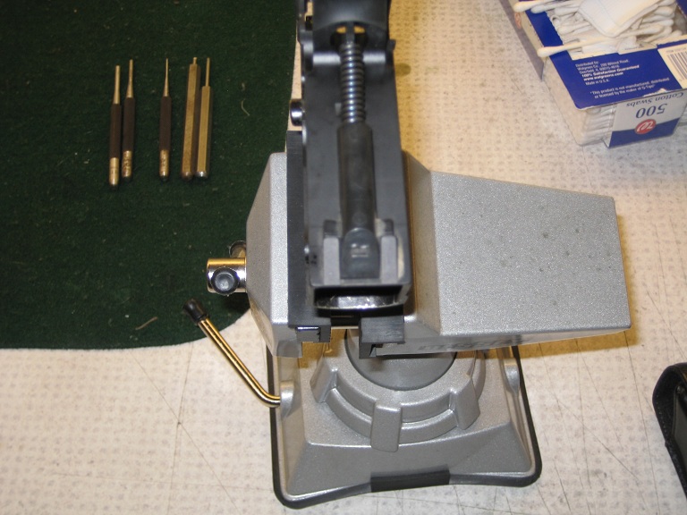
You will need a Sig Armorer’s tool (http://www.sigsauer.com/SigStore/sig-sauer-armorers-tool-94.aspx $34.95 from Sig, available at Brownells for less), and two punches. The Sig Armorer’s tool is just a multi screw driver with 4 different tips, most of the time you’ll only be using 3 of the four. You can get by without the Sig Armorer’s Tool, but its much easier and probably safer as well to do this with it. You will also need a 1.5 mm pin punch and 3mm punch. 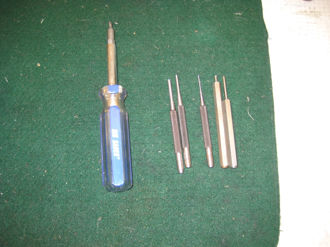
Using the Flat Tip screw driver portion of the SAT (Sig Armorer’s Tool), remove the grip screws. Some later model guns have torx head screws. 
Next remove the Takedown Lever by pushing it to the left while rotating it in a circle. 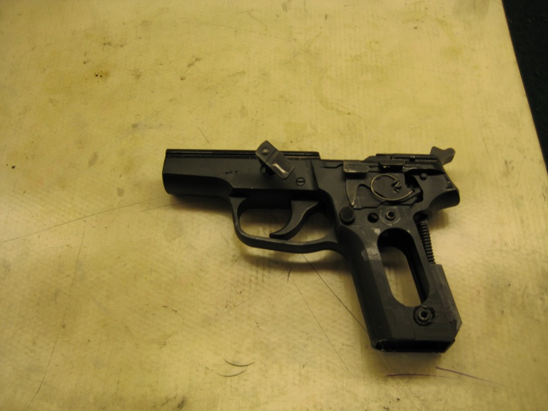
|
|
|
|
|
[#1]
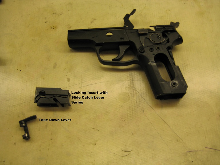
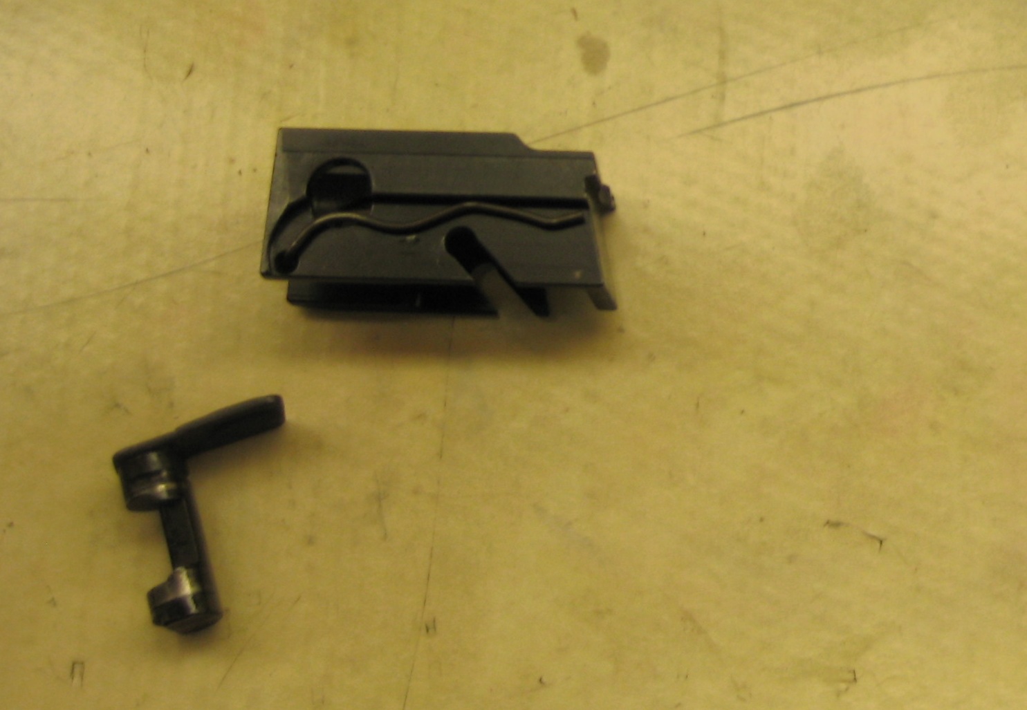
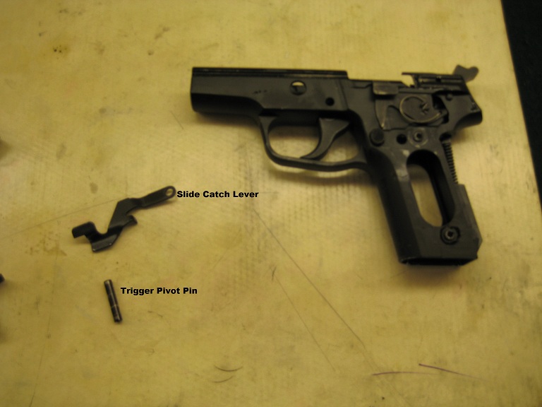
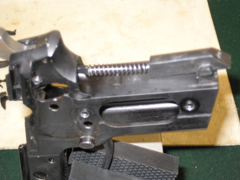
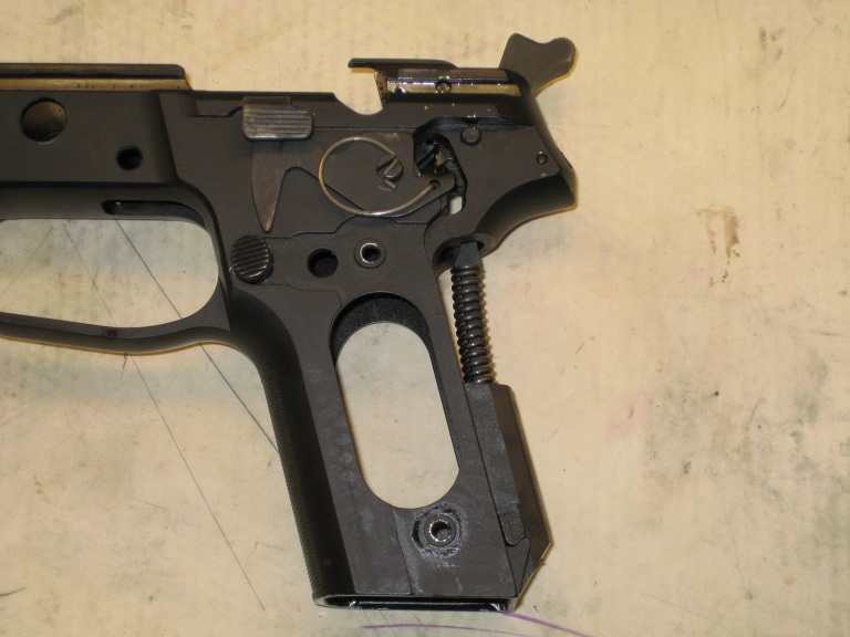
Once the Take Down Lever is removed, you can pull the Locking Insert, (Locking block) and the Slide Catch Lever Spring out of the receiver. The Slide Catch Lever Spring is loosely attached to the Locking Insert and is held in place by pressure from the side of the receiver. You can see the Slide Catch Lever sticking up in the photo below.
The Slide Catch Lever and the Trigger and Trigger Bar are kept in place by the Trigger Pivot Pin. Once the Locking Insert is removed, simply push the Trigger Pivot Pin out to the right. The Slide Catch Lever will fall right out. 
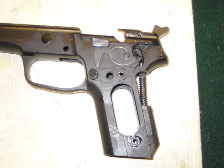
Next, turn the receiver over to the other side. The Trigger and Trigger Bar are held in place by the Trigger Bar Spring. Pay close attention to how the trigger bar spring is connected. The rear has to be hooked into the correct spot otherwise you will have malfunctions. 


|
|
|
|
|
[#2]
Remove the Trigger Bar Spring. This can be done with just your fingers.

To remove the Trigger and Trigger Bar, you need to tilt them slight to the right to clear a small channel or shelf. This can be somewhat tricky. I’ve worked on some guns where the Trigger Bar just doesn’t want to come out at all, and others where it pops out very easily. The important thing to remember is DO NOT FORCE IT. There are some things on this gun where its okay to use force to either remove or reinstall a part. THIS IS NOT ONE OF THEM! 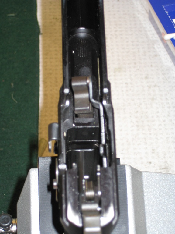

The Trigger Bar and Trigger will come out as a single piece. They also have to go back in as a single piece. 
Here they are separated for cleaning. 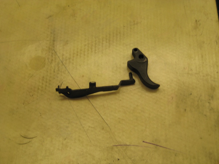
|
|
|
|
|
[#3]
Thanks, I just poked my eye out!
 No, seriously, thanks for doing the rest of the breakdown. I have an old W. German 220 that has never been cleaned up. It has to be scrungy in there. No, seriously, thanks for doing the rest of the breakdown. I have an old W. German 220 that has never been cleaned up. It has to be scrungy in there. |
|
|
|
|
[#4]
Now turn the receiver over to the other side again. Its time to take out the Decocking Lever, Bearing, and Spring.
Using the small notched flat tip bit in SAT, I gently pry up the Decocking lever spring at the rear, (closest to the hammer). 
Once its loose, the Decocking Lever Spring can just be lifted right out. This will usually cause the Decocking Lever Bearing to fall right out. It fits directly underneath, the Decocking Lever, inside the magazine well. I moved it for picture purposes. It is also in the correct orientation for reassembly. (Put it back this way) 
The Decocking Lever now easily lefts off the receiver. Here are the three parts together. 
|
|
|
|
|
[#5]
Now its time to remove the Mainspring, the Hammer Strut, and the Mainspring Seat. Turn the gun over so the muzzle end is pointing towards the ground. Use the same notched end of the SAT, and insert it into the small slot of the Mainspring Seat, (black plastic piece. Be careful when removing the Mainspring Seat. Its under pressure and the spring could go flying off somewhere.
Older versions of the Classic Series Pistols, (220’s, 226’s, 225’s and early model 239’s) will have a metal Mainspring Seat. You will need to use this bit in your SAT to remove it. 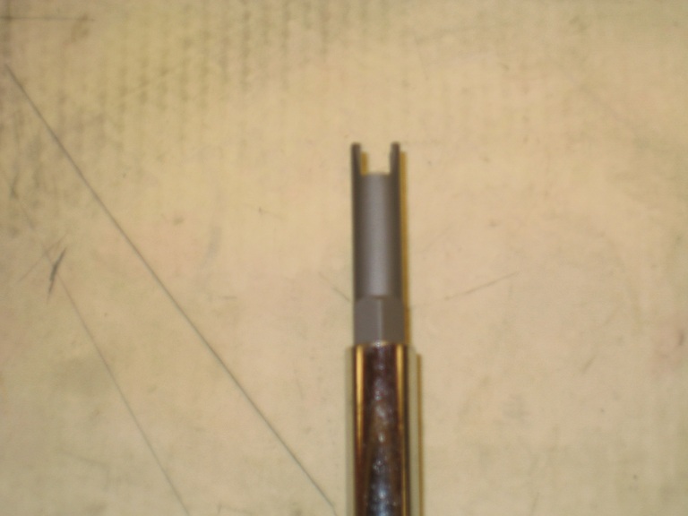
If you have a black plastic Mainspring Seat as pictured, you will use this small notched bit of the SAT. 
|
|
|
|
|
[Last Edit: MaxxII]
[#6]
You only need to use enough pressure to get the Seat to ride over the two small stirrups it sits in. It should look like this:
With the Seat removed, you’re left with the Mainspring and the Hammer Strut. 


Notice the Hammer Strut has two notches in it. The front notch is what the Hammer sits on. Remember this for later. Now we’re left with the Hammer, and Sear Assemblies…. Before we can remove these parts, we need to free the Sear Spring. it’s a captive spring, so no worries about it flying off somewhere. Turn the gun right side up and look down the Magazine well. You should see the spring being held by the Sear Spring Pin. This pin does not get removed. 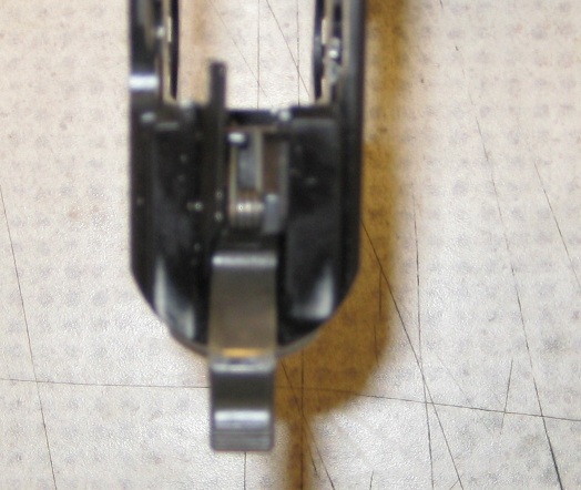
Take the small notched bit of the SAT and slide the spring into the notched portion. Push down, and to the right, and allow the arm of the spring to pop free of the Sear Spring Pin. It should look like this now: 


|
|
|
|
|
[Last Edit: MaxxII]
[#7]
Once the Sear Spring is loose, you can push out the Hammer Pivot pin and the Sear Pivot Pin.

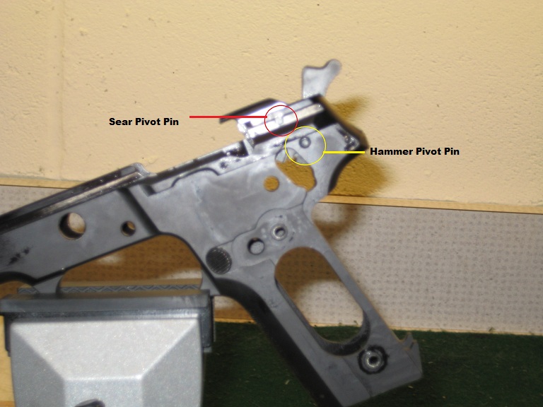

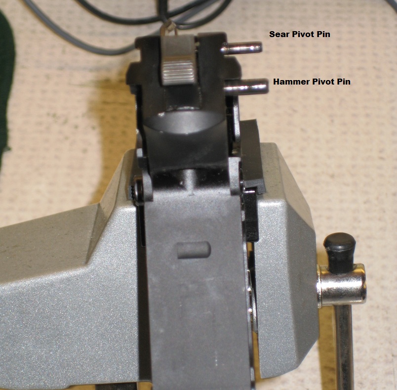
Once the Sear Pivot Pin is free, the following parts should fall right out: 
Once the Sear and its associated parts are out, you can remove the Hammer. 
This is what you’re left with: 
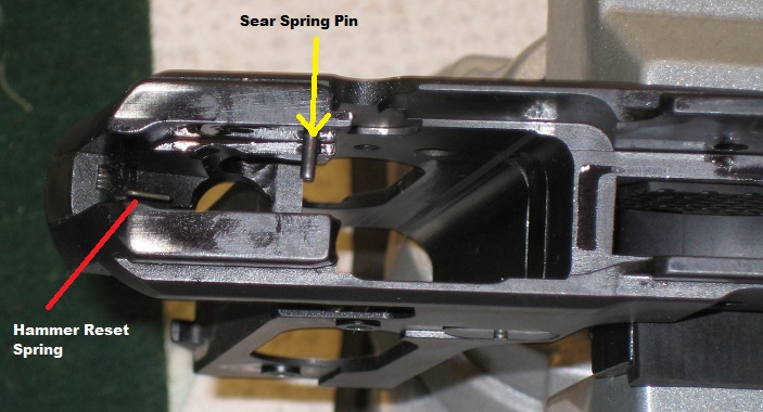
The only reason you would need to remove these two parts if they break. If you are converting your pistol (manufactured after 2005) to a DAK trigger you will need to remove the Hammer Stop by removing the Hammer Stop Pin with a 1/16" punch and take out the Hammer Reset Spring. Then reinstall the Hammer Stop and Hammer Stop Pin . You will also be replacing the Hammer, Hammer Strut, Sear, Sear Spring, Safety Lever, and Trigger Bar. The Decocking Lever Assembly, (Decocking Lever, Bearing, and Spring) will be removed. |
|
|
|
|
[Last Edit: MaxxII]
[#8]
Next is to remove the Magazine Catch. This is only done if you want to change the Magazine Release Button from the normal right handed use, (left side of gun) over to the left handed use, (right side of gun). Interestingly enough, I asked all of the lefties in the Department if they wanted me to swap their mag releases over to left handed use. All of them said no. They had gotten used to right handed mag releases and were more comfortable with them that way.
To disassemble the Mag Catch, you will need to use the smallest pointed bit of the SAT. 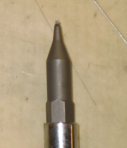
On the front of the Mag Catch, facing the rear of the trigger guard is a very tiny part, the Mag Catch Stop. This stop is what “Stops” the mag catch from coming free from the receiver. Take the pointed bit of the SAT and depress the Mag Catch Stop like this: 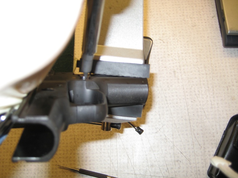
BE CAREFUL!!! The Mag Catch Stop sits on top of a very small spring, (The Mag Catch Stop Spring). This spring will happily launch across the room never to be seen again. (Ask me how I know…sigh). Let the Mag catch Stop out slowly to avoid losing the Mag Catch Stop Spring. It should look like this: 

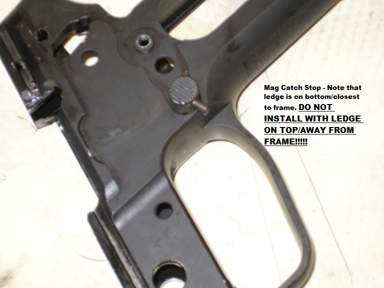
Note that the Mag Catch Stop has a beveled edge/ledge on one side. This beveled edge/ledge is installed closest to the frame. The tension from the Mag Catch Stop Spring pushes the Mag Catch Stop against the frame. This beveled edge/ledge prevents the Mag Catch Stop from falling out or coming loose. BE CAREFUL!!! Make sure to re-install the Mag Catch Stop with the Beveled side/ledge down, (IE closest to the frame and trigger guard). Getting this backwards will make it almost impossible to get the Mag Catch Stop out of the frame. |
|
|
|
|
[Last Edit: MaxxII]
[#9]
The Mag Catch, Mag Catch Stop, and Springs look like this when removed from the receiver:

Please note that the Mag Catch Stop Spring is pictured here still inside the Mag Catch Stop. These are two separate parts that I chose not to separate for this picture. 
Finally, flip the pistol over, and remove the Mag Catch Support Plate. 
To do this, take either the flat tip screw driver bit or the small notched bit of the SAT and push the support plate towards the rear of the pistol. Reinstall it on the opposite side. Since none of the Lefties in the Department wanted a left handed mag catch on their pistols, I reinstalled all mag catch parts back the way they had come out. If you’re changing your mag catch from right handed to left handed, just do the same things on the opposite side. With the Mag Catch Support plate in place, take the Mag Catch, install the Mag Catch Spring in the hole it rides in, and slide the Mag Catch back into position. Note that the cut out portion of the Mag Catch faces the inside of the mag well. Also take care not to bend the Mag Catch Spring when reinstalling the Mag Catch. 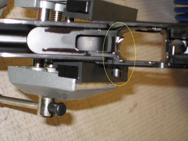
|
|
|
|
|
[#10]
Reinstall the Mag Catch Stop. Don’t forget the beveled end/ledge goes in closest to the frame. Once the Mag Catch is reinstalled, I find it easiest to go ahead and reinstall the Decocking Lever.
Take the Decocking Lever Bearing and place it like so. It should go in with no force needed. If you’re having to force it, stop, make sure your placing it in like so, and try again. Sometimes they will hang up somewhat, but they can always be adjusted into place. 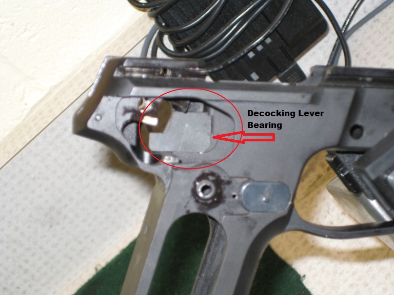
Once the Decocking Lever Bearing is in place, hold it there with your fingers, while you place the Decocking Lever on top of it, place the Deecoking Lever Spring in position, and then using the notched bit of the SAT, install the spring. It will look like this when finished: 
Now place the Ejector on the Sear Spring Pin, like so. The first hole on the Ejector fits on the Sear Spring Pin. 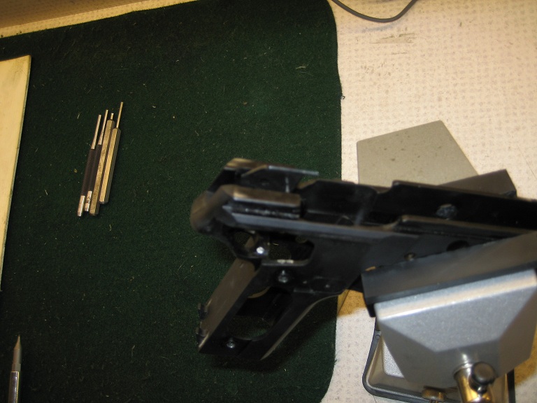
Then place the Hammer in. The Hammer pin fits UNDER the Hammer Reset Spring. 
Here is another look at the Hammer Reset Spring
|
|
|
|
|
[#11]
Once you have the Hammer Secured under the Hammer Reset Spring, (pull back gently against the spring. If the Hammer comes straight back, you didn’t get the spring over the Hammer Pin.), Secure the Hammer by reinstalling the Hammer Pivot Pin.
Now for the most awkward part…Installing the Sear. The Sear goes into the gun in this direction… 
The flat face of the sear butts up against the hammer. It also has to fit UNDER the Sear Spring Pin, so you’re having to wiggle it up through there. With practice, it gets easier. But the fastest way to do that I’ve been taught is to take a Q Tip and insert into the gap in the back of the Sear like this: 
Be sure to keep the Sear Pivot Pin hole clear so you can insert the pin. Once you’ve got the Sear threaded under the Sear Spring Pin, and onto the Hammer, slide the Sear Pivot Pin over slightly so that you can partially secure the Sear in place. 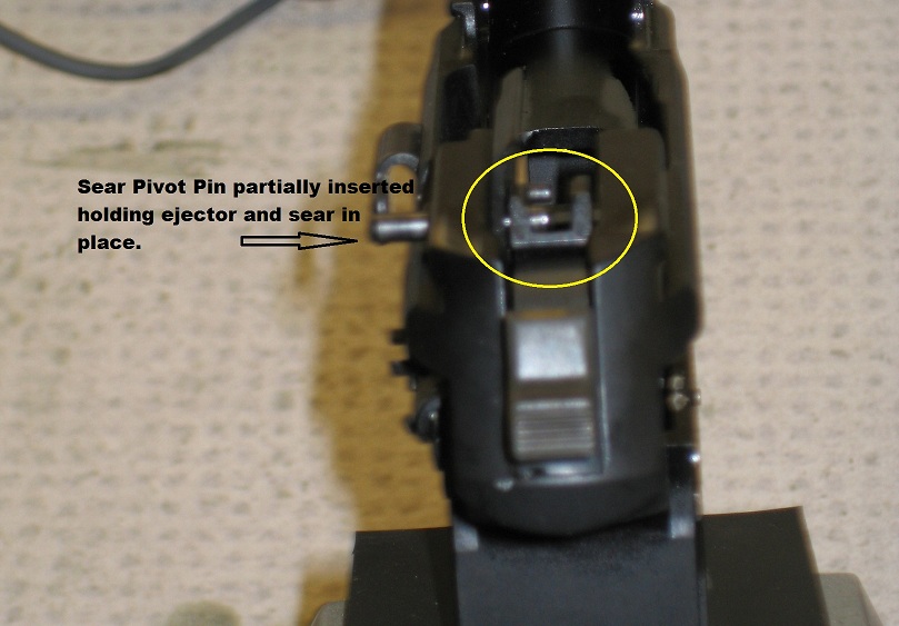
Some guns are looser than others, and I’ve had Sear Pivot Pins fall right out, so I have learned to apply a slight bit of pressure against the side of the pin to keep it in place when installing the Sear parts. Now its time install the Sear Spring 
The Sear Spring sits inside the Sear. 
Once you have the Sear Spring in place, slide the Sear Pivot Pin over slightly more to contain the Sear Spring. Leave room for the Safety Lever on the right, outside the Sear. Don’t secure the upper arm of the Sear Spring just yet. You still need to install the Safety Lever before you get there. |
|
|
|
|
[#12]
The Safety Lever looks like an elephant to me. When you install the Safety Lever, its important to note that the rear “leg” goes behind the ledge of the Sear, (closer to the Hammer), and the bent/front “leg” actually sits on the ledge of the Sear. Here are some horrible pictures to show you what I’m talking about:


If you’re installing a Short Reset Trigger (SRT) from Sig, this is where you will do it. Here is a comparison photo of the different parts… 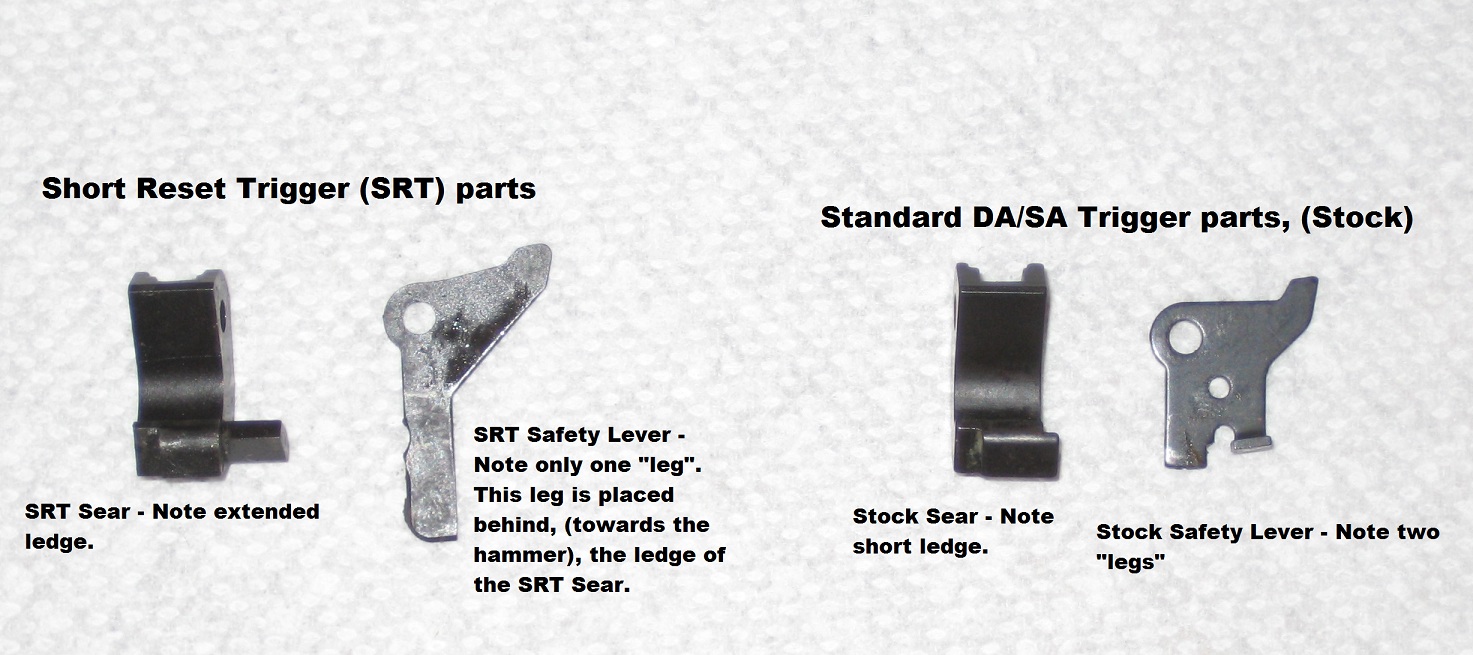
If you are installing the SRT trigger only, you do not need to completely disassemble the gun. Remove the slide, take off the grips. Using the notched end of the SAT, unhook the Sear Spring. Take the 1.5 mm punch and lightly tap the Sear Pivot Pin over until you can remove the Sear, Sear Spring, and Safety Lever. Take the Sear and Safety lever and put them aside. Use the Q tip as shown previously on the Sear, and thread it through. Gently slide the Sear Pivot Pin over until the SRT Sear is partially held. Install the Sear Spring, and again slide the Sear Pivot Pin over to capture the Sear Spring. Then take the the SRT Safety Lever, and place the single “leg” behind the extended ledge of the SRT Sear. Once you have everything lined up, slide the Sear Pivot Pin all the way over. Congrats, you’ve just installed an SRT Trigger. Make sure the Sear Pivot Pin isn’t sticking too far out on one side or the other. It is in the slide rail, and will bind up the gun. Once the Sear Pivot Pin is properly in place, and the Sear, the Sear Spring, and the Safety lever are lined up and held in place by the Sear Pivot Pin, secure the Sear Spring by using the notched end bit of the SAT to do so. Make sense? 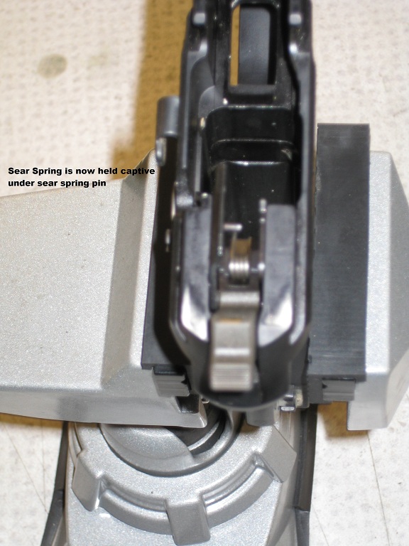
|
|
|
|
|
[#13]
Now we’re ready to reinstall the Hammer Strut, and Mainspring.
Here’s the tricky part about this…the front notch of the Hammer Strut, needs to be threaded as far back as possible. You’ll know you’ve done it right the hammer actually moves forward a slight distance when you push up on the Hammer Strut. If the hammer does not move forward, you’re not in the right place.

With the Hammer Strut in the right position, place the Mainspring back on the Strut, and then place the Mainspring Seat over the base of the Mainspring. Using your fingers, push against the Mainspring Seat, compressing the Mainspring, and allowing the seat to slip over the Stirrups that hold the Seat in place. 
|
|
|
|
|
[#14]
Now to put the Trigger and Trigger bar in place.
They have to be connected before placing them in, (Trigger Bar connects to the top/smaller hole in the Trigger from the right side). Don’t forget you have to get past the choke point as seen in this picture:
Just like taking it apart, it works best if you tilt it sideways somewhat to get it in. Once the Trigger Bar is in place, things will look like this: 
Now insert the front hook of the Trigger Bar Spring into the tiny hole behind the Mag Catch Support Plate.
Then connect the rear hook to the divot in the Trigger Bar. When you’re done it should look like this: 
Now insert the Trigger Pivot Pin. 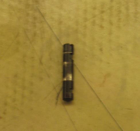
You notice that it has a pair of cuts in the side and a slot machined into one end. The slots lock into the Locking Insert, (locking block) and the slot is designed to perfectly fit the flat tip notched bit from SAT. Put the Trigger Pivot Pin in the receiver so that the slot is on the left side of the gun, and the cuts are facing forwards towards the muzzle. 

Note that you need to install the Slide Catch Lever into the receiver before you install the locking insert. |
|
|
|
|
[Last Edit: MaxxII]
[#15]
I needed both hands to do this next part, so I couldn’t take photo’s of it…
Place the Locking Insert into the receiver. As you press downwards and back, using the SAT to turn the Trigger Pivot Pin 90 degree’s towards the rear of the gun. The Locking Insert should drop right in. If it doesn’t, you may need to fiddle with the Trigger Pivot Pin until you get the alignment just right between the Locking Insert and the Trigger Pivot Pin cuts. This is what it look likes when you’ve got it…. 

Now reinsert the Take Down Lever, twisting it in a circle as you go. Once this is done, all you have left is to put the grips and grips screws back on. You should function check the pistol to ensure you didn’t forget something. Pull the trigger in DA mode. It should function normally. Pull the trigger in SA mode. It should also function normally. Cock the hammer, and hit the decocted. It should function normally. Pull the trigger and hold it back. Then rack the slide. Let go of the trigger. You should feel the sear reset. If this is a stock sear and safety lever, there will be some play in the trigger before the slack takes up. If you just installed an SRT sear and safety lever, there will be no creep in the trigger and the reset will be shorter. Finally take an unloaded magazine and insert it into the gun. Turn the gun so the butt is parallel to the ground, and release the magazine. Do this from several angles to ensure you did not retighten the grips screws to the point that they bind the magazine and keep it from dropping free. Congratulations, you’ve just disassembled and reassembled your Sig Classic Series pistol frame. Disassembly/reassembly of the slide to follow later. |
|
|
|
|
[Last Edit: MaxxII]
[#16]
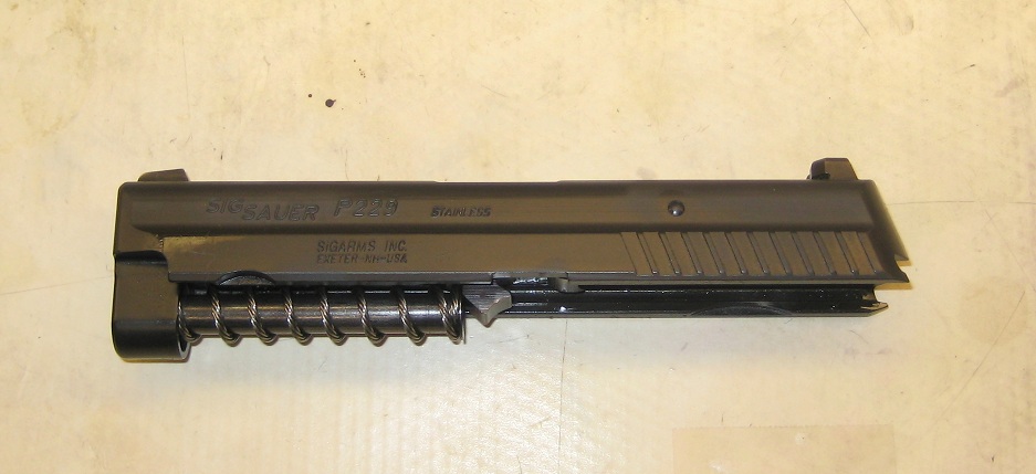
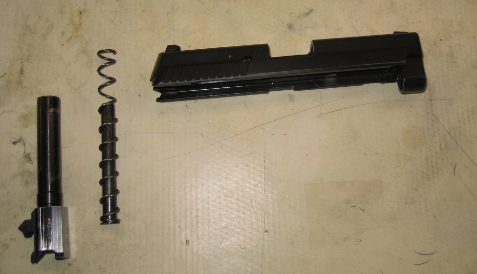
With the slide removed from the frame, remove the barrel and recoil spring and guide rod.
Next I remove the extractor. To do this you will need either the small notched tip of the SAT, or a similarly sized flat tip bladed screw driver. 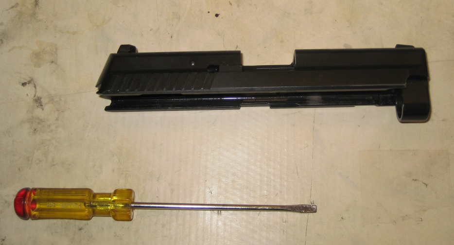
Insert it into the space between the extractor and the extractor pin, and twist the blade, this will pop the extractor loose. 
In this picture, the extractor has fallen loose, and tumbled into the breech of the pistol. 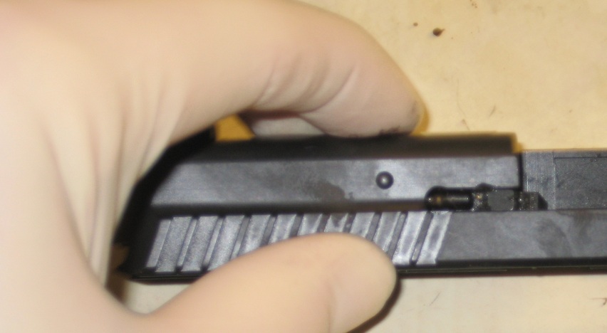
With the extractor out, remove the extractor pin and extractor spring, they will look like this: 
This is what gets removed most often from the slide, and this doesn’t happen very often at all. To remove everything else from the inside of the slide you will need a 3mm punch, a hammer/mallet, the screw driver used before or something similarly small sized, and a block. Sig will cheerfully sell you a polymer armorer’s block with lots of holes drilled through it for about $39.99. Or you can take a small piece of 2x4 and drill a hole through the middle of it, and it will do the same thing for a whole lot less money. Obviously, I bought the block before learning about the 2x4 DIY version…..save your money, spend it on ammo. 
Taking the 3mm cup tipped punch, knock out the Firing Pin Position Pin, from right to left.. The Firing Pin Position Pin has a knurled side, which holds it in place and prevents it from being knocked loose from the wrong side. This is one the parts where you may use force to remove it. Most guns are relatively easy to knock loose. They will require some force, but nothing obscene. I’ve had one that was just a hair too large and I had to beat the hell out of it to get it to come loose. Seriously, it was ridiculous how much and how hard I had to hit the damn thing. 


With the firing pin position pin out the firing pin will rest against the punch, and make it either difficult to remove the punch or impossible, depending on the size of the punch. To get to the punch loose, turn the slide upside down so you’re looking at the bottom of it. 
|
|
|
|
|
[Last Edit: MaxxII]
[#17]
Note the position of the firing pin in the above picture. Use a punch or the screw driver etc to gently depress the Firing Pin Safety Lock, (The little half moon looking thingy) this will release the firing pin and you can remove the punch now. Notice the position of the firing pin now. 
The firing pin and firing pin spring should come loose along with the firing pin safety lock and firing pin safety lock spring: 
Here is what the entire disassembled slide will look like (minus sights) with all parts labeled. To reassemble I start with the firing pin and spring. Reinsert the firing pin and spring into the slide. Note the position of the firing pin in the following picture. For reference, the bottom of the picture (as you’re looking it) is the right side of the slide: 
With the firing pin positioned like shown above, reinsert the firing pin safety lock spring and firing pin safety lock in the slide. The raised half moon part goes to the rear of the slide…for some reason I neglected to take a picture of this step. In order to get the firing pin back into proper place, you will need to use the screw driver or another punch to gently depress the firing pin safety lock. While you’re doing this, you want to gently push the firing pin forward, (towards the muzzle). When the firing pin is as far forward as possible, let up on the firing pin safety lock. 
When you let up on the firing pin safety lock, the firing pin will be kept in place. 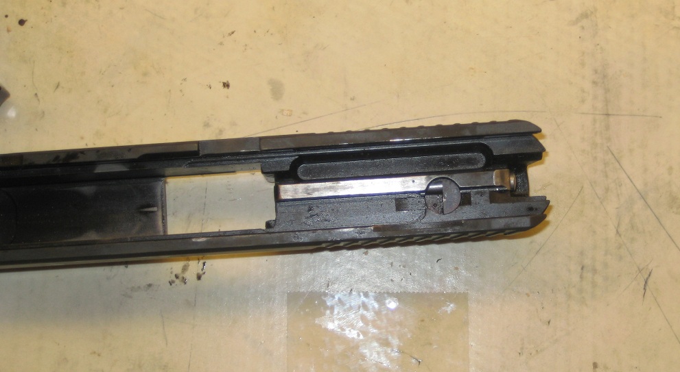
Now its time to install the Firing Pin Position Pin. Sig states the Firing Pin Position Pin should be replaced every time its been removed. Personally, I’ve reused them without incident. I will not reuse them more than once however. The knurls on the side of it get crushed down and allow the pin to work loose while firing. Install this from the opposite side it came loose, IE, install the firing pin position pin from the left side of the slide. 
To get the firing pin position pin into the proper alignment, its necessary to push the firing pin forward again while pushing down on the firing pin position pin. 
Stop pushing when you feel resistance. This should be right where the knurls on the pin touch the slide. If its after that, replace the firing pin position pin as Sig states. 
Once you cannot push the firing pin position pin any farther with your fingers, place the slide back on the block so that the hole for the pin is directly over the hole in the middle of your block. Then hit it back into place with your hammer. It should require less force to reinstall than it did to come loose. 
Stop hammering when the pin is flush with the side of the slide: 
Now its time to reinstall the extractor. Start by reinserting the extractor spring in the hole, and then insert the extractor pin. 
|
|
|
|
|
[Last Edit: MaxxII]
[#18]
Line up the extractor with the extractor pin, the short ledge should be lined up with the pin. As shown in the picture:

You will need the screwdriver or a punch to push the extractor straight back into the hole. When done properly, it will pop right in place. When its not, it wont go in at all. I didn’t have a third hand to take a picture of that step, sorry. When everything is finished, it will once again look like this… 
|
|
|
|
|
[#19]
Place holder
|
|
|
|
|
[Last Edit: MaxxII]
[#20]
Maintenance and Parts Replacement Schedule
Detailed Disassembly and inspection should be done every three years or every 5000 rounds. Whichever comes first. Barrel...........................................................................................If the pistol exhibits keyholing or unacceptable accuracy. Recoil Spring.............................................................................3 years or 5000 rounds, whichever comes first. Extractor Spring..........................................................................20000 rounds Extractor.......................................................................................20000 rounds Firing Pin......................................................................................20000 rounds Firing Pin Spring.........................................................................20000 rounds Firing Pin Safety Lock Spring....................................................20000 rounds Takedown Lever...........................................................................20000 rounds Slide Catch Lever Spring............................................................10000 rounds Trigger Bar Spring.........................................................................10000 rounds Decocking Lever Spring................................................................10000 rounds Magazine Spring.............................................................................When Magazine fails to lock the slide back. |
|
|
|
|
[#21]
Originally Posted By Intune69:
Thanks, I just poked my eye out! No, seriously, thanks for doing the rest of the breakdown. I have an old W. German 220 that has never been cleaned up. It has to be scrungy in there. Depending on how much you've shot it, you're going to be HORRIFIED at what you find when you disassemble the gun. I would also add that if you have an older gun with the Metal Mainspring Seat, I would Highly reccomend getting the Sig Armorer's Tool, (SAT). Trying to remove the Seat without the goofy H shaped bit is a damn nightmare otherwise. |
|
|
|
TN, USA
|
[#22]
Great instructions. Definitely needs to be tacked.
I'd also include that the Hammer Reset Spring needs to be removed for a DAK installation with a 1/16'' punch. |
|
|
|
[#23]
Good catch, thank you.
My Department doesnt use the DAK trigger system and consequently, I havent played with one since attending the Armorer's Course. My Dad has a 229 DAK, but I never really play with it much. When I get some time and a chance to tear his apart, I'll post up comparison pictures of the DAK, and the DA/SA Classic Pistols. Unless you've got one and feel like doing it? Regardless, I appreciate the feedback Rightwing87. |
|
|
|
TN, USA
|
[#24]
Originally Posted By MaxxII:
snip This is what you’re left with: http://www.ar15.com/media/viewFile.html?i=35463 http://www.ar15.com/media/viewFile.html?i=35462 The only reason you would need to remove these two parts if they break. If you are converting your pistol (manufactured after 2005) to a DAK trigger you will need to remove the Trigger Reset Spring with a 1/16th pin punch. You will also be replacing the Hammer, Hammer Strut, Sear, Sear Spring, Safety Lever, and Trigger Bar. The Decocking Lever Assembly, (Decocking Lever, Bearing, and Spring) will be removed. Needs to be "Hammer Reset Spring" I'd maybe change the wording to "remove the Hammer Stop by removing the Hammer Stop Pin with a 1/16" punch and take out the Hammer Reset Spring. Then reinstall the Hammer Stop and Hammer Stop Pin." |
|
|
|
[#25]
Thank you! Hate it when I goof up terms like that.
Fixed the screw up and changed the wording on the original post to what you suggested. It read better and made more sense. |
|
|
|
|
[#26]
As requested by OP, I saved the thread to PDF. It isn't cleaned up or anything, just a print to PDF and if someone wants to host it more permanently, by all means!
http://www.multiupload.com/POKC9QH640 |
|
|
|
|
[#27]
Originally Posted By JSteensen:
As requested by OP, I saved the thread to PDF. It isn't cleaned up or anything, just a print to PDF and if someone wants to host it more permanently, by all means! http://www.multiupload.com/POKC9QH640 AWESOME!!! Thank you! |
|
|
|
|
[#28]
Anytime. Needed to do something to celebrate me picking up my first Sig tomorrow. West German P226 I traded for. I see your manual being very useful to me for the tear down and inspection.
|
|
|
|
|
[#29]
Hope it helps.
I'd love to be able to scan & post the Sig Armorer's Manual but that's verboten by Sig without permission... Hence this thread.... |
|
|
|
|
[#30]
Quick question on the slide, what holds in the extractor to the breech block? Im disassembling my 228 for US Anodizing to do their Navy package to it and that is the last thing before I box it up, is there any trick to getting it out or does it pretty much just pop out?
|
|
|
|
|
[#31]
The extractor pops right when "pried" out.
Take a small flat bladed screwdriver, hold it so the blade is vertical and gently slide it into the narrow space between the slide and the extractor. There is a spring and a small rod behind it that you will need to hang on to. Put them in a small ziploc baggie and label them so you dont lose them. I should be able to take apart an upper and upload photo's here in the next couple of day so you can see how to put them together. Hope that helps. |
|
|
|
|
[#32]
The disassembly/reassembly of the slide has been added to the first page of this thread.
As before, please feel free to point out any errors/mistakes, or improper terminology used in the posts so that they can be corrected. And again, feel free to download and save the images in anyway useful to you. This is meant as a resource to be used by any and all. If you want to download it and turn it into a PDF file, please do so. |
|
|
|
|
[#33]
Successfully completed spring replacement on my beloved 228 using this guide but have a question.My 228 is a stamped slide internal extractor.I need to replace the double roll pins as their WAY overdue.Iv'e read that the larger roll pin goes with the slit up and the smaller one goes slit down but that is all iv'e found.Can I just knock the old ones out and put the new ones in without any disassembly?
|
|
|
|
|
[#34]
Originally Posted By MadBodhi:
Successfully completed spring replacement on my beloved 228 using this guide but have a question.My 228 is a stamped slide internal extractor.I need to replace the double roll pins as their WAY overdue.Iv'e read that the larger roll pin goes with the slit up and the smaller one goes slit down but that is all iv'e found.Can I just knock the old ones out and put the new ones in without any disassembly? Can you post a picture of it so that I can see it clearly? I wasnt trained on the older models, we used the newer versions in the class. I would assume, (not having seen it to be sure) that you could knock one loose, replace it, and then do the same with the other. Hopefully, someone with experiance on the older models can answer. Have you called Sig and asked them? |
|
|
|
|
[#35]
Originally Posted By MaxxII:
Originally Posted By MadBodhi:
Successfully completed spring replacement on my beloved 228 using this guide but have a question.My 228 is a stamped slide internal extractor.I need to replace the double roll pins as their WAY overdue.Iv'e read that the larger roll pin goes with the slit up and the smaller one goes slit down but that is all iv'e found.Can I just knock the old ones out and put the new ones in without any disassembly? Can you post a picture of it so that I can see it clearly? I wasnt trained on the older models, we used the newer versions in the class. I would assume, (not having seen it to be sure) that you could knock one loose, replace it, and then do the same with the other. Hopefully, someone with experiance on the older models can answer. Have you called Sig and asked them? All you are doing is running the roll pins through the slide and breechblock. Use your 1/8" punch to hold the slide and breechblock together as the breechblock is under spring tension from the firing pin safety. Tap the large rollpin in from the opposite side, then install the small rollpin with the opening 180 degrees from the large rollpin. Easy peasy. |
|
|
|
|
[Last Edit: 762AP]
[#36]
Outstanding post! Thanks much.
Since you posted this thread, I was able to convert my KD coded P220 to non spur hammer. There were a couple "propritary" things regarding the P-220 compared to your post, but overall, it was 99% on the spot. I couldn't have done it without this thread. I and my now "modern" hammer 220 thank you. |
|
|
|
|
[#37]
Glad it helped. You got an IM.
|
|
|
|
|
[#38]
Originally Posted By nf9648:
Originally Posted By MaxxII:
Originally Posted By MadBodhi:
Successfully completed spring replacement on my beloved 228 using this guide but have a question.My 228 is a stamped slide internal extractor.I need to replace the double roll pins as their WAY overdue.Iv'e read that the larger roll pin goes with the slit up and the smaller one goes slit down but that is all iv'e found.Can I just knock the old ones out and put the new ones in without any disassembly? Can you post a picture of it so that I can see it clearly? I wasnt trained on the older models, we used the newer versions in the class. I would assume, (not having seen it to be sure) that you could knock one loose, replace it, and then do the same with the other. Hopefully, someone with experiance on the older models can answer. Have you called Sig and asked them? All you are doing is running the roll pins through the slide and breechblock. Use your 1/8" punch to hold the slide and breechblock together as the breechblock is under spring tension from the firing pin safety. Tap the large rollpin in from the opposite side, then install the small rollpin with the opening 180 degrees from the large rollpin. Easy peasy. Thanks for the reply. Sorry I didnt see this until now. |
|
|
|
NH, USA
|
[#39]
New here, I have a in depth understanding of the Sig Sauer pistols. Just took a look through on this thread. To add something that I see a lot of people who shouldn't be taking there gun apart do when re-assembling it, that causes the gun to be non-functioning.
When installing the hammer, there is a pressed in bar horizontally in the hammer above the hammer pivot pin holes. You must loop that underneath the hammer reset spring and make sure it stays in that orientation. If you just push the hammer straight in you will damage the hammer reset spring. Also once you have it in the correct position with the hammer pivot pin installed do not push the hammer to far forward or the reset spring will fall beneath that bar and be damaged as you continue re-assembly. This is an obvious sign to look for when someone hands you there gun and the hammer no longer resets, and you ask them did someone take this gun apart, they always say(lying) no. But the only way it can happen is described above. |
|
|
FL, USA
|
[#40]
Thank you for your time and trouble.
|
|
|
|
[#41]
You're welcome.
I hope it helps you or someone else out. |
|
|
|
UT, USA
|
[#42]
Thank you for your help. Several years ago I bought a police trade-in P228 and have wanted to trade the trigger out for the short one. Thanks to your fine photos and help this went well this morning. Only had a bit of trouble with the reinstallation of the locking block, but it went right in when it was ready. Contributions like yours is what makes ar15.com such a world class site.
|
|
|
|
[#43]
Thanks!
|
|
|
|
SC, USA
|
[#44]
Thank you. I just used the thread to assemble a 226 tacops. The note about the hammer strut moving the hammer fixed my initial wrong assembly. Thanks. Also, I thought I missed a part because the SRT safety lever is different than the one in the video I watched the first time.
|
|
|
|
[#45]
Glad it helped.
|
|
|
|
OR, USA
|
[#46]
Thank You! for this thread.
|
|
|
|
[Last Edit: MaxxII]
[#47]
You're welcome!
ETA @Corsair Your IM inbox is full. |
|
|
|
TN, USA
|
[#48]
I have a P228 and I took it apart to clean it and now I can’t get the locking insert installed. I did get it back in but the slide would not go back on. There are bird on the feed ramp on the barrel so it is hitting the locking insert is my guess. So I took it back out and am having problems getting it back together. I have checked a few places and they say that the insert is to high and that the trigger pin is not positioned correctly. To be honest I’m at a loss. Any ideas?
|
|
|
|
[#49]
The notches in the trigger pin should be facing downwards...check to see how the trigger pin is oriented and rotate as necessary. It might take some fidgeting to get it to finally seat...
|
|
|
|
TN, USA
|
[#50]
Once I faced them downward the block went right in. But know the slide will not go on. It looks as if the feed ramp on the barrel is hitting the block. I marked where the barrel ends and the block begins and that’s where the slide stops. The take down lever is pointed down.
|
|
|
 Win a FREE Membership!
Sign up for the ARFCOM weekly newsletter and be entered to win a free ARFCOM membership. One new winner* is announced every week!
You will receive an email every Friday morning featuring the latest chatter from the hottest topics, breaking news surrounding legislation, as well as exclusive deals only available to ARFCOM email subscribers.

AR15.COM is the world's largest firearm community and is a gathering place for firearm enthusiasts of all types.
From hunters and military members, to competition shooters and general firearm enthusiasts, we welcome anyone who values and respects the way of the firearm.

Subscribe to our monthly Newsletter to receive firearm news, product discounts from your favorite Industry Partners, and more.
Copyright © 1996-2024 AR15.COM LLC. All Rights Reserved.
Any use of this content without express written consent is prohibited.
AR15.Com reserves the right to overwrite or replace any affiliate, commercial, or monetizable links, posted by users, with our own.