|
[#1]
It's certainly not rocket science, but it still best done by a pro. There are a lot of little things that a do it yourselfer can miss or do wrong, which can result in a lock out.
Switching from mechanical to electronic is pretty straight forward. The other way around isn't as easy. |
|
|
|
[#2]
Is it possible to switch any mechanical lock to electric?
|
|
|
|
[#3]
Is it possible to switch any mechanical lock to electric?
If it is a UL rated lock, then it is very likely. Most modern UL rated locks share a common footprint, so they are fairly easy to switch around from one style to another, and from one manufacturer to another. |
|
|
|
[#4]
I happen to be writing an article describing the reverse...updating an old safe combo lock to having a modern digital keypad. If you're lock is a typical Group II gun safe lock (like my nearly 20 year old Browning is), then it's pretty simple, and I have a combo lock I was just about to put up on eBay. IM me and I can help you out with this. I'll probably have my article written and posted this weekend (or sooner if I can find the time) |
|
|
|
[#5]
Unfortunately the only informationI have on the safe lock is that it contains a "Type I Electronic Lock"....not sure what the differences are between Type I and Group 2 locks....
P2B |
|
|
|
[#6]
Quoted:
I happen to be writing an article describing the reverse...updating an old safe combo lock to having a modern digital keypad. If you're lock is a typical Group II gun safe lock (like my nearly 20 year old Browning is), then it's pretty simple, and I have a combo lock I was just about to put up on eBay. IM me and I can help you out with this. I'll probably have my article written and posted this weekend (or sooner if I can find the time) Has this article been posted yet? |
|
|
|
[#7]
Quoted:
Unfortunately the only informationI have on the safe lock is that it contains a "Type I Electronic Lock"....not sure what the differences are between Type I and Group 2 locks.... P2B Who made it? What brand safe do you have? You shouldn't have any problems replacing a group 1 electronic lock with either a Sargent & Greenleaf 6730, or a LaGard 3300. They'll cost you between $75-100 NIB. The only issue I see is if you have a Sentry or Stack On brand safe. They use their own type of locks (think cheap chinese-like crap  ) , that are much differant from a standard group 1 or 2 mechanical safe lock like those I listed above. ) , that are much differant from a standard group 1 or 2 mechanical safe lock like those I listed above.
|
|
|
|
[#8]
Thanks for the help...My safe is a Cannon Safe. I can take some photos and hopefully there might be some input on converting the electronic lock to a manual combo. I will post safe model info as well.
Thanks for reaching out and providing help.....I appreciate it! P2B |
|
|
|
[#9]
Quoted:
Thanks for the help...My safe is a Cannon Safe. I can take some photos and hopefully there might be some input on converting the electronic lock to a manual combo. I will post safe model info as well. Thanks for reaching out and providing help.....I appreciate it! P2B I'll explain the swap in some detail, so you can decide if you want to attempt it, or hire a pro. This is a swap that as an experienced pro takes me about 30 minutes (going from mechanical to electronic is easier). A Cannon more than likely has a LaGard electronic lock, but it could have a Sargent & Greenleaf. Either way, the mounting footprint (mounting screw pattern) will be indentical to that used by a S&G 6730 or LaGard 3300 mechanical lock (all 4 use same screw holes). There's six steps below that take some knowledge (or at least some coaching 1) Screw new lock body to the door with the lock bolt pointing in the same direction as the one on the lock you removed was pointing. 2) Install dial ring on outer door. You must center the ring around the dial spindle hole in the lock body, so that the dial doesn't bind when turned. The dial ring gets screwed to the outer door using the same holes as the keypad studs. But the holes which the screws pass through on the ring are slightly elongated, so there's some "play" , for exact centering over the hole in the lock body where the dial spindle enters it. You don't just screw it on in "any old position". I usually look through the hole in the ring and into the hole in the lock, and line the two holes up visually... like using a peep sight. 3) Cutting the dial spindle to the correct length (they all come a long, universal length, and must be cut to fit the door thickness of the safe you're mounting it on). This is precision stuff, and likely the most critical step. Too long, it hits the lock's back cover when it's turned... if real long, it won't turn at all when the cover plate on the lock gets screwed in place. Cut it too short, it's ruined... you can't glue it back together. The perfect fit is so that the back edge of the spline key is flush with, or a little above, the face of the driver wheel. I usually screw the driver on the spindle (with spindle inserted into lock, with dial installed onto ring) until the proper spline match-up (explained later), then mark spindle with a felt-tip marker at the driver wheel. I then unscrew it, remove dial from ring. Thread driver wheel back onto spindle, well past your marking, then cut spindle at 3 threads towards dial end from where felt-tip pen was kept from marking spindle by driver. After cutting, unthreading driver will now "clean up" the threads where you cut. 4) Next is installing the dial into the ring and spindle through lock. Thread driver wheel onto the (cut to length) dial spindle and spline the driver wheel correctly to match the handing of the lock (handing = which of four directions the lock's bolt is pointing). There's 4 possible mounting positions, like the compass points on a map. You don't choose or decide, it'll only fit your safe's pre-drilled/tapped lock body screw mounting holes two ways, and only one is correct ... with the lock bolt interferring with the bolt linkage. The driver wheel will be marked at four positions (north, south, east , west), and have a small cut-out in the threads by each, to accept the spline key. The driver wheel is threaded onto the spindle until the marking that corresponds with the way the lock is handed is aligned with the single spline cut in the dial spindle, and the dial is not too loose, nor too tight. The spline key is then inserted between spline cut in driver and the single spline cut in the spindle, locking the spindle & driver wheel into one piece. BTW.... those markings on the driver wheel are not N, S, E, W.... they are VU (vertical up), VD (vertical down), RH (right-handed), LH (left-handed), and corrrespond with which way the lock-bolt is pointing. Most common handing is RH for most safes, but on gun safes, which typically have the handle below the lock, it's usually VD. (Not a hard & fast rule, but most safes' locks are mounted so the lock's bolt points toward the handle, because that's where the lock bolt blocks the handle and/or door bolt linkages). 5) Installing the lock's rear cover plate and relocker. If I were you, I'd take a picture of how the electronic lock is installed before you remove it, so you can install the relocker the same way it was. 6) After it's installed, it's time to set your combination. I've had new locks come from the box set at 50-50-50 or sometimes they're set at 50-25-50. Obviously, this must be changed. When doing so, the 3rd number should never be near what's called the "drop-in point", because if it is, is causes the lock to bind up. If splined correctly, the drop-in point will be at about the number "7" on the dial. The 3rd number should not be set within about 12-13 numbers of this number in both directions, or not between 95-20 (I use 90-25 to be safe). It doesn't matter on the 1st two numbers, just the 3rd. Directions on combo changing procedure, and a special tool needed to do so, come with the new locks. Always always always test everything, especially combo, 10 times in a row with the door open. If it does not work EVERY time, reset it again. Problems are 1,000 times easier to solve with the door open, vs with the door locked and unable to be opened. 
|
|
|
|
[#10]
Great Info!! The lock is a Lagard....Thank You for the most detail I have been able to find...If I could, I would like to take a photo one step at a time and post PRIOR to destroying a working assembly!!
I think I would like to purchase a S&G combo to begin the project. I will post the front and rear/inner workings of the current lock prior to moving forward. Any help is appreciated! P2B |
|
|
|
[#11]
Don't forget that doing your own work will likely void the warranty on the safe, lock, or both. Not always the end of the world, but certainly worth keeping in mind.
|
|
|
|
[#12]
rfb45colt,
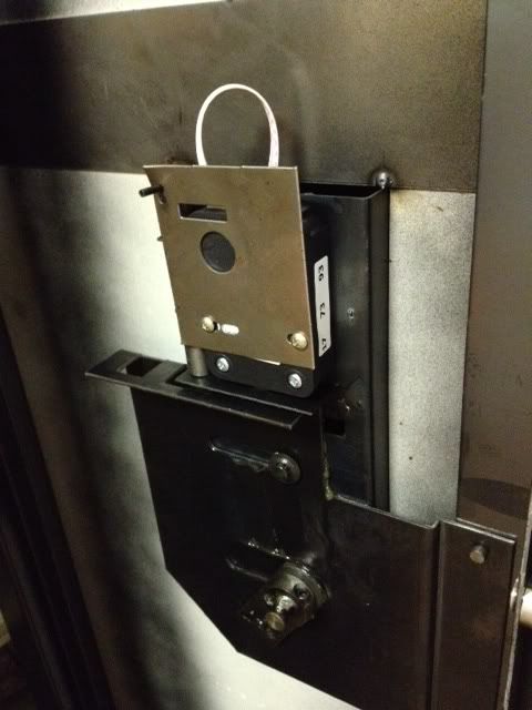
I am attempting to post two photos of my lock (hope it works, if not I will attempt again). The first shows the lock (a LaGard I believe) from the front...the second shows the internal view of the lock from the inside of the safe door. Prior to starting and buying a new S&G lock, I want to confirm it is appropriate.... P2B  [/URL]" /> [/URL]" />
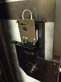 [/URL]" /> [/URL]" />
Quoted:
Quoted:
Thanks for the help...My safe is a Cannon Safe. I can take some photos and hopefully there might be some input on converting the electronic lock to a manual combo. I will post safe model info as well. Thanks for reaching out and providing help.....I appreciate it! P2B I'll explain the swap in some detail, so you can decide if you want to attempt it, or hire a pro. This is a swap that as an experienced pro takes me about 30 minutes (going from mechanical to electronic is easier). A Cannon more than likely has a LaGard electronic lock, but it could have a Sargent & Greenleaf. Either way, the mounting footprint (mounting screw pattern) will be indentical to that used by a S&G 6730 or LaGard 3300 mechanical lock (all 4 use same screw holes). There's six steps below that take some knowledge (or at least some coaching 1) Screw new lock body to the door with the lock bolt pointing in the same direction as the one on the lock you removed was pointing. 2) Install dial ring on outer door. You must center the ring around the dial spindle hole in the lock body, so that the dial doesn't bind when turned. The dial ring gets screwed to the outer door using the same holes as the keypad studs. But the holes which the screws pass through on the ring are slightly elongated, so there's some "play" , for exact centering over the hole in the lock body where the dial spindle enters it. You don't just screw it on in "any old position". I usually look through the hole in the ring and into the hole in the lock, and line the two holes up visually... like using a peep sight. 3) Cutting the dial spindle to the correct length (they all come a long, universal length, and must be cut to fit the door thickness of the safe you're mounting it on). This is precision stuff, and likely the most critical step. Too long, it hits the lock's back cover when it's turned... if real long, it won't turn at all when the cover plate on the lock gets screwed in place. Cut it too short, it's ruined... you can't glue it back together. The perfect fit is so that the back edge of the spline key is flush with, or a little above, the face of the driver wheel. I usually screw the driver on the spindle (with spindle inserted into lock, with dial installed onto ring) until the proper spline match-up (explained later), then mark spindle with a felt-tip marker at the driver wheel. I then unscrew it, remove dial from ring. Thread driver wheel back onto spindle, well past your marking, then cut spindle at 3 threads towards dial end from where felt-tip pen was kept from marking spindle by driver. After cutting, unthreading driver will now "clean up" the threads where you cut. 4) Next is installing the dial into the ring and spindle through lock. Thread driver wheel onto the (cut to length) dial spindle and spline the driver wheel correctly to match the handing of the lock (handing = which of four directions the lock's bolt is pointing). There's 4 possible mounting positions, like the compass points on a map. You don't choose or decide, it'll only fit your safe's pre-drilled/tapped lock body screw mounting holes two ways, and only one is correct ... with the lock bolt interferring with the bolt linkage. The driver wheel will be marked at four positions (north, south, east , west), and have a small cut-out in the threads by each, to accept the spline key. The driver wheel is threaded onto the spindle until the marking that corresponds with the way the lock is handed is aligned with the single spline cut in the dial spindle, and the dial is not too loose, nor too tight. The spline key is then inserted between spline cut in driver and the single spline cut in the spindle, locking the spindle & driver wheel into one piece. BTW.... those markings on the driver wheel are not N, S, E, W.... they are VU (vertical up), VD (vertical down), RH (right-handed), LH (left-handed), and corrrespond with which way the lock-bolt is pointing. Most common handing is RH for most safes, but on gun safes, which typically have the handle below the lock, it's usually VD. (Not a hard & fast rule, but most safes' locks are mounted so the lock's bolt points toward the handle, because that's where the lock bolt blocks the handle and/or door bolt linkages). 5) Installing the lock's rear cover plate and relocker. If I were you, I'd take a picture of how the electronic lock is installed before you remove it, so you can install the relocker the same way it was. 6) After it's installed, it's time to set your combination. I've had new locks come from the box set at 50-50-50 or sometimes they're set at 50-25-50. Obviously, this must be changed. When doing so, the 3rd number should never be near what's called the "drop-in point", because if it is, is causes the lock to bind up. If splined correctly, the drop-in point will be at about the number "7" on the dial. The 3rd number should not be set within about 12-13 numbers of this number in both directions, or not between 95-20 (I use 90-25 to be safe). It doesn't matter on the 1st two numbers, just the 3rd. Directions on combo changing procedure, and a special tool needed to do so, come with the new locks. Always always always test everything, especially combo, 10 times in a row with the door open. If it does not work EVERY time, reset it again. Problems are 1,000 times easier to solve with the door open, vs with the door locked and unable to be opened. |
|
|
|
[#13]
I am having issues posting the photos (from photobucket)....any tips on that and I can fix it. The link text is below if someone more knowledgable would like to give it a go...
http://i1055.photobucket.com/albums/s518/Plan2build/ce1e5ab6.jpg http://i1055.photobucket.com/albums/s518/Plan2build/12999502.jpg |
|
|
|
[#14]
Think I have it now:

|
|
|
|
[#15]
Quoted:
Great Info!! The lock is a Lagard....Thank You for the most detail I have been able to find...If I could, I would like to take a photo one step at a time and post PRIOR to destroying a working assembly!! I think I would like to purchase a S&G combo to begin the project. I will post the front and rear/inner workings of the current lock prior to moving forward. Any help is appreciated! P2B I'm confused. The old electric lock is LaGard? Or the new mechanical lock is LaGard? The photo shows SecuRam. Does SecuRam = LaGard? |
|
|
|
[#16]
I have had fairly bad luck with the Securam keypads. Good call on wanting to swap it out.
It will have the exact same footprint as any of the other locks already mentioned. It's an easy swap. |
|
|
|
[#17]
You are correct and I was in error. When disassembling to take photos, I saw that the lock is indeed a SecuRam. Cannon also utilized both S&G and Lagard according to the user instructions with the safe. Thanks for the clarification.
P2B Quoted:
Quoted:
Great Info!! The lock is a Lagard....Thank You for the most detail I have been able to find...If I could, I would like to take a photo one step at a time and post PRIOR to destroying a working assembly!! I think I would like to purchase a S&G combo to begin the project. I will post the front and rear/inner workings of the current lock prior to moving forward. Any help is appreciated! P2B I'm confused. The old electric lock is LaGard? Or the new mechanical lock is LaGard? The photo shows SecuRam. Does SecuRam = LaGard? |
|
|
|
[#18]
RFB45Colt provided great instructions for the lock replacement. I purchased a Sargent and Greenleaf 6730 combination lock kit that included all parts necessary for this modification. The overall lock change from electronic to manual combo lock took about 45 minutes and was extremely straight forward and required no special tools....just an understanding of the mechanics of the lock. I am embedding some photos of the procedure....
Overall I am extremely satisfied how it turned out...no more battery replacements. If anyone wants the electronic lock I removed, drop me an IM (old lock already gone 8/24). Thanks for all the help provided...I would recommend this conversion for all those thinking about it but imagining it is difficult. Take your time, have a beer close by, and give it a try. Best advice is to ALWAYS try the combination with the door OPEN....this should be done multiple times to make sure you have the correct installing! Again, thanks to this forum for getting me through this!! P2B Quoted:
Quoted:
Thanks for the help...My safe is a Cannon Safe. I can take some photos and hopefully there might be some input on converting the electronic lock to a manual combo. I will post safe model info as well. Thanks for reaching out and providing help.....I appreciate it! P2B I'll explain the swap in some detail, so you can decide if you want to attempt it, or hire a pro. This is a swap that as an experienced pro takes me about 30 minutes (going from mechanical to electronic is easier). A Cannon more than likely has a LaGard electronic lock, but it could have a Sargent & Greenleaf. Either way, the mounting footprint (mounting screw pattern) will be indentical to that used by a S&G 6730 or LaGard 3300 mechanical lock (all 4 use same screw holes). There's six steps below that take some knowledge (or at least some coaching 1) Screw new lock body to the door with the lock bolt pointing in the same direction as the one on the lock you removed was pointing. Very simple....use of a magnetic screw driver is recommended....really no difficulty here. 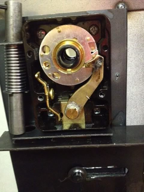
2) Install dial ring on outer door. You must center the ring around the dial spindle hole in the lock body, so that the dial doesn't bind when turned. The dial ring gets screwed to the outer door using the same holes as the keypad studs. But the holes which the screws pass through on the ring are slightly elongated, so there's some "play" , for exact centering over the hole in the lock body where the dial spindle enters it. You don't just screw it on in "any old position". I usually look through the hole in the ring and into the hole in the lock, and line the two holes up visually... like using a peep sight. This was very straight forward and the "peep site" reference was on target 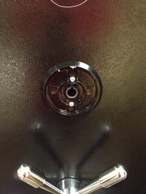
3) Cutting the dial spindle to the correct length (they all come a long, universal length, and must be cut to fit the door thickness of the safe you're mounting it on). This is precision stuff, and likely the most critical step. Too long, it hits the lock's back cover when it's turned... if real long, it won't turn at all when the cover plate on the lock gets screwed in place. Cut it too short, it's ruined... you can't glue it back together. The perfect fit is so that the back edge of the spline key is flush with, or a little above, the face of the driver wheel. I usually screw the driver on the spindle (with spindle inserted into lock, with dial installed onto ring) until the proper spline match-up (explained later), then mark spindle with a felt-tip marker at the driver wheel. I then unscrew it, remove dial from ring. Thread driver wheel back onto spindle, well past your marking, then cut spindle at 3 threads towards dial end from where felt-tip pen was kept from marking spindle by driver. After cutting, unthreading driver will now "clean up" the threads where you cut. Scariest part...but worked out great with minimal effort. Cut was straight forward and provided nice action on the combo dial. 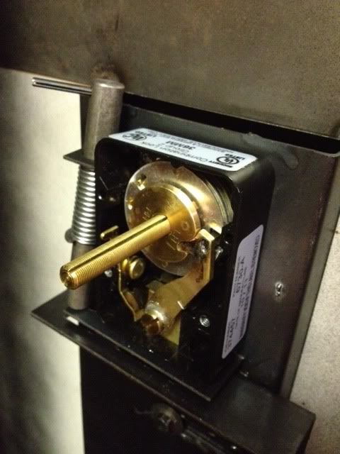
4) Next is installing the dial into the ring and spindle through lock. Thread driver wheel onto the (cut to length) dial spindle and spline the driver wheel correctly to match the handing of the lock (handing = which of four directions the lock's bolt is pointing). There's 4 possible mounting positions, like the compass points on a map. You don't choose or decide, it'll only fit your safe's pre-drilled/tapped lock body screw mounting holes two ways, and only one is correct ... with the lock bolt interferring with the bolt linkage. The driver wheel will be marked at four positions (north, south, east , west), and have a small cut-out in the threads by each, to accept the spline key. The driver wheel is threaded onto the spindle until the marking that corresponds with the way the lock is handed is aligned with the single spline cut in the dial spindle, and the dial is not too loose, nor too tight. The spline key is then inserted between spline cut in driver and the single spline cut in the spindle, locking the spindle & driver wheel into one piece. BTW.... those markings on the driver wheel are not N, S, E, W.... they are VU (vertical up), VD (vertical down), RH (right-handed), LH (left-handed), and corrrespond with which way the lock-bolt is pointing. Most common handing is RH for most safes, but on gun safes, which typically have the handle below the lock, it's usually VD. (Not a hard & fast rule, but most safes' locks are mounted so the lock's bolt points toward the handle, because that's where the lock bolt blocks the handle and/or door bolt linkages). Again, a very straight forward instruction....be careful with the spline key as the kit only provides one. Went on smooth and as planned! 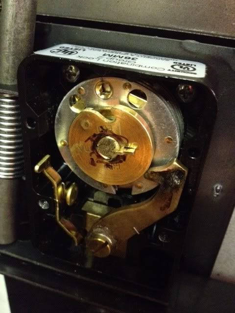
5) Installing the lock's rear cover plate and relocker. If I were you, I'd take a picture of how the electronic lock is installed before you remove it, so you can install the relocker the same way it was. 6) After it's installed, it's time to set your combination. I've had new locks come from the box set at 50-50-50 or sometimes they're set at 50-25-50. Obviously, this must be changed. When doing so, the 3rd number should never be near what's called the "drop-in point", because if it is, is causes the lock to bind up. If splined correctly, the drop-in point will be at about the number "7" on the dial. The 3rd number should not be set within about 12-13 numbers of this number in both directions, or not between 95-20 (I use 90-25 to be safe). It doesn't matter on the 1st two numbers, just the 3rd. Directions on combo changing procedure, and a special tool needed to do so, come with the new locks. The back plate and relocker were installed with no issues....very straight foward. Here is a picture of the front with the replacement combination lock!!! 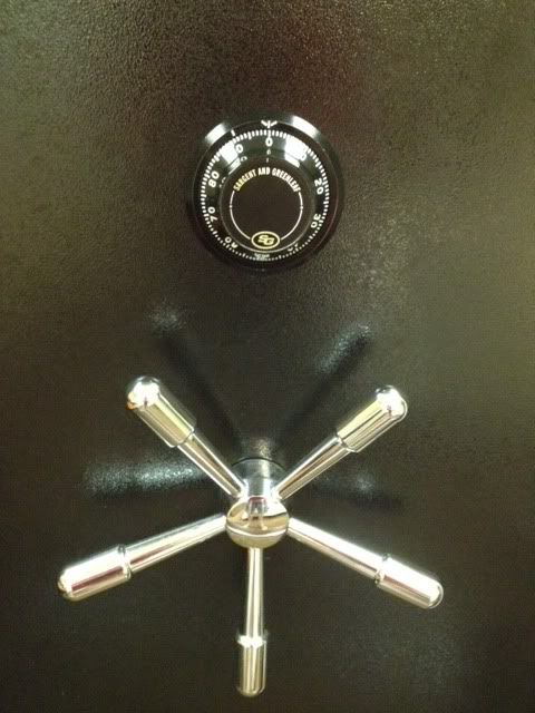
Always always always test everything, especially combo, 10 times in a row with the door open. If it does not work EVERY time, reset it again. Problems are 1,000 times easier to solve with the door open, vs with the door locked and unable to be opened. |
|
|
 Win a FREE Membership!
Sign up for the ARFCOM weekly newsletter and be entered to win a free ARFCOM membership. One new winner* is announced every week!
You will receive an email every Friday morning featuring the latest chatter from the hottest topics, breaking news surrounding legislation, as well as exclusive deals only available to ARFCOM email subscribers.

AR15.COM is the world's largest firearm community and is a gathering place for firearm enthusiasts of all types.
From hunters and military members, to competition shooters and general firearm enthusiasts, we welcome anyone who values and respects the way of the firearm.

Subscribe to our monthly Newsletter to receive firearm news, product discounts from your favorite Industry Partners, and more.
Copyright © 1996-2024 AR15.COM LLC. All Rights Reserved.
Any use of this content without express written consent is prohibited.
AR15.Com reserves the right to overwrite or replace any affiliate, commercial, or monetizable links, posted by users, with our own.