|
Posted: 6/16/2014 9:15:24 AM EDT
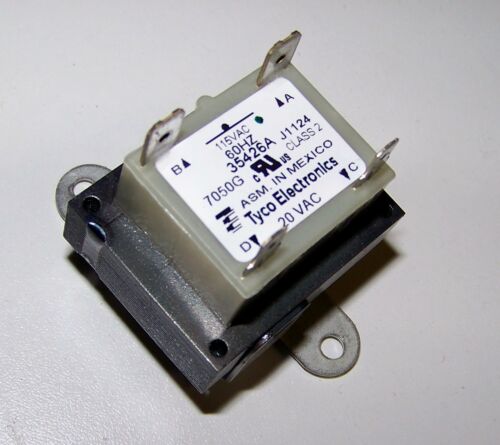
Garage door opener Issue. Primary windings showing an open. Confirmed using a scope that one of the primary windings is busted. 120V is at the pins but no output. Pic below. I can;t find this anywhere online. Maybe the power of GD can help me.

|
|
|
|
[#1]
Continuity check acros the pins of the primary show an open?
Did you check the continuity of the secondary? What is the load of the device it drives? Transformers are common and dirt. |
|
|
|
[#2]
What is secondary output voltage?
How many watts? Should be easy to find if you know these things. |
|
|
|
[#3]
That exact transformer is an OEM product made by Tyco. It is unlikely you will be able to get the same model unless you find it from a surplus place.
On the other hand, if you know the voltage of the secondary and the anticipated load, finding a substitute should be trivial. |
|
|
|
[#4]
Quoted:
Continuity check acros the pins of the primary show an open? Did you check the continuity of the secondary? What is the load of the device it drives? Transformers are common and dirt. Secondary shows 5 ohms. Not sure on the load. The transformer goes into the logic board which is driven on 24v. |
|
|
|
[#5]
Take it to granger.
|
|
|
|
[#6]
Quoted:
What is secondary output voltage? How many watts? Should be easy to find if you know these things. Secondary voltage should be 24Vac The output feeds into a diode bridge and into a 220uF 50V cap. I assume that circuit there converts it to 24VDC. |
|
|
|
[#7]
|
|
|
|
[#8]
Quoted:
Here is your answer: http://www.liftmaster.com/lmcv2/productdetail/19724/elite-series-wall-mount-garage-door-opener/ Yep, I only wish. Can't afford a new garage door opener now. I am thinking of using this in lieu of the PCB mount one. 
|
|
|
|
[#9]
At a loss since I can't find any info at all for the OEM transformer.
|
|
|
|
[#10]
This is what I found so far online.
Get a 24 V transformer (it is probably not more than this) and connect its primary to a Variac and its secondary to the opener. Slowly increase the variac until everything works. (check every volt or so from 5 to 24). Measure the output voltage of the transformer, add 10-20%, you've probably got the secondary rating. If it is near a standard value like 12 or 24, this is most likely correct. |
|
|
|
[#11]
24VAC is going to be ~33VDC once rectified.
|
|
|
|
[#12]
Quoted:
24VAC is going to be ~33VDC once rectified. Yep. So I need like a 120V primary and a 18v secondary |
|
|
|
[#13]
Probably dropping through a regulator or zener rail. Usually a regulator in a circuit like that.
|
|
|
|
[#14]
Quoted:
Yep. So I need like a 120V primary and a 18v secondary Quoted:
Quoted:
24VAC is going to be ~33VDC once rectified. Yep. So I need like a 120V primary and a 18v secondary Eh, it probably uses 24vac and regulates it on the board. I just mentioned that so you did not try to get by with a 24VDC power supply. |
|
|
|
[#15]
Quoted:
Eh, it probably uses 24vac and regulates it on the board. I just mentioned that so you did not try to get by with a 24VDC power supply. Quoted:
Quoted:
Quoted:
24VAC is going to be ~33VDC once rectified. Yep. So I need like a 120V primary and a 18v secondary Eh, it probably uses 24vac and regulates it on the board. I just mentioned that so you did not try to get by with a 24VDC power supply. Im gonna try using the Variac and see where the opener operates. |
|
|
|
[#16]
Look for a fuse on the board and thst will tell you the max current for the secondary,
|
|
|
|
[#17]
Quoted:
Look for a fuse on the board and thst will tell you the max current for the secondary, Only fuse it has on the board is a 10 amp. |
|
|
|
[#18]
Quoted:
Continuity check acros the pins of the primary show an open? If so, quite likely that it was overloaded, and the embedded thermal fuse blew. |
|
|
|
[#19]
40 VA will get you pretty close to that 10 amps that the fuse indicates.
Make sure all the gears and tracks are lubed. If the thermal fuse in the original blew, it may be because it was working too hard. |
|
|
|
[#20]
Quoted:
24VAC is going to be ~33VDC once rectified. If they didn't cost-reduce the full-wave rectifier out of the thing and just dropped in a diode or two. Cheap bastards are like that. |
|
|
|
[#21]
http://www.te.com/catalog/pn/en/1611535-2?RQPN=7143C
Looks like that specific one is OEM only or something. I would just get a 50va transformer and replace it. |
|
|
|
[#22]
Quoted:
http://www.te.com/catalog/pn/en/1611535-2?RQPN=7143C Looks like that specific one is OEM only or something. I would just get a 50va transformer and replace it. yeah but if I exceed what the logic board is looking for ( 24V ) then I may mess it up. Here is a pic of the rectifier circuit. 
|
|
|
|
[#23]
Quoted:
yeah but if I exceed what the logic board is looking for ( 24V ) then I may mess it up. Here is a pic of the rectifier circuit. http://i61.tinypic.com/iw84uh.jpg Quoted:
Quoted:
http://www.te.com/catalog/pn/en/1611535-2?RQPN=7143C Looks like that specific one is OEM only or something. I would just get a 50va transformer and replace it. yeah but if I exceed what the logic board is looking for ( 24V ) then I may mess it up. Here is a pic of the rectifier circuit. http://i61.tinypic.com/iw84uh.jpg That is a full wave rectifier. |
|
|
|
[#24]
You get a 110V/24V transformer rated at 50Va.
Hold on and I will find you a link to Amazon or something. |
|
|
|
[#25]
what about this?
|
|
|
|
[#26]
The transformers on Amazon are the big ones. I sell the little ones. Bump this thread tomorrow and I will look to see what we have in stock and get a part number and post that and you can buy it locally.
|
|
|
|
[#27]
Quoted:
what about this? http://i.ebayimg.com/00/s/MTQyNVgxNjAw/$(KGrHqZHJEkFC(hB8jkNBQmE0nuoHw~~60_12.JPG That is 20VAC. You said it was 24VAC? |
|
|
|
[#28]
Hmmm.. the plot sickens.
I see 4 diodes in one area, a couple more in another, and more through hole lands than a single winding transformer would account for. The transformer may be putting out multiple voltages on the secondary side. OP, can you look at the PC traces on the secondary side of the board to confirm or deny? |
|
|
|
[#29]
Quoted:
That is 20VAC. You said it was 24VAC? Quoted:
Quoted:
what about this? http://i.ebayimg.com/00/s/MTQyNVgxNjAw/$(KGrHqZHJEkFC(hB8jkNBQmE0nuoHw~~60_12.JPG That is 20VAC. You said it was 24VAC? Logic board drives off of 24V DC. Im not 100% sure what the secondary A/C voltage is supposed to be. But it seems that every Genie transformer out there is 20 V A/C at the secondary. Maybe this model is the same. |
|
|
|
[#30]
Quoted:
If so, quite likely that it was overloaded, and the embedded thermal fuse blew. Quoted:
Quoted:
Continuity check acros the pins of the primary show an open? If so, quite likely that it was overloaded, and the embedded thermal fuse blew. True. OP, see if you can unwind the tape covering the primary wires. Sometimes the thermal fuse is added after the transformer is assembled and is accessible by cutting away the tape. If you bypass it you will be able to measure the secondary output. I'm not a fan of the variac method since under voltage can sometimes be more destructive than over voltage. |
|
|
|
[#31]
Quoted:
Hmmm.. the plot sickens. I see 4 diodes in one area, a couple more in another, and more through hole lands than a single winding transformer would account for. The transformer may be putting out multiple voltages on the secondary side. OP, can you look at the PC traces on the secondary side of the board to confirm or deny? So the 2 center top holes are the secondary The 2 center bottom are the primary. The other holes are for mounting / ground.
|
|
|
|
[#32]
Quoted:
Take it to granger. This. |
|
|
|
[#33]
24VAC 40VA is your typical transformer used in HVAC. Cheap and easy to find. Quoted:
40 VA will get you pretty close to that 10 amps that the fuse indicates. 24V @ 40VA = 1.67 A. You're not even close. |
|
|
|
[#34]
Really need the exact specs from the transformer. If its 115v to 24v I have 50 of them. These are a real common transformer in the HVAC field.
|
|
|
|
[#35]
Quoted:
Really need the exact specs from the transformer. If its 115v to 24v I have 50 of them. These are a real common transformer in the HVAC field. yeah, thats the problem. It's a genie proprietary part and there are no specs for it out there. Ive spent all day searching. |
|
|
|
[#36]
Does anyone here have a Genie Excelerator ISD series grage door opener? If so can you take a reading what your secondary is outputting on your transformer?
|
|
|
|
[#37]
Tried a 16.5vAC 40VA transformer I had at the house. While it was enough power to get the backlight at the keypad and the trip sensors lit up it wasn't enough to drive the logic board or the motor.
|
|
|
|
[#38]
Quoted:
24VAC is going to be ~33VDC once rectified. No it's not. Only if you rectify it, let a filter cap charge up with no load, maybe. As soon as you load it, it's back down to RMS. |
|
|
|
[#39]
Quoted: yeah, thats the problem. It's a genie proprietary part and there are no specs for it out there. Ive spent all day searching. Quoted: Quoted: Really need the exact specs from the transformer. If its 115v to 24v I have 50 of them. These are a real common transformer in the HVAC field. yeah, thats the problem. It's a genie proprietary part and there are no specs for it out there. Ive spent all day searching. Funny, mine was a screw drive xcellerator. I never installed the new board....too bad I gave it to the guy who bought my opener.  |
|
|
|
[#40]
Quoted:
Did you call them and see if they sell the entire board? My Genie, back a house ago, had a two year warranty. Then sent me a free board because mine had a stuck relay. Sears repair depot may even have the board in stock. Funny, mine was a screw drive xcellerator. I never installed the new board....too bad I gave it to the guy who bought my opener.
Quoted:
Quoted:
Quoted:
Really need the exact specs from the transformer. If its 115v to 24v I have 50 of them. These are a real common transformer in the HVAC field. yeah, thats the problem. It's a genie proprietary part and there are no specs for it out there. Ive spent all day searching. Funny, mine was a screw drive xcellerator. I never installed the new board....too bad I gave it to the guy who bought my opener.
This opener is 10 + years old................
|
|
|
|
[#41]
genie opener
buy new end of story. Transformers burn up usually from another issue. You can find a transformer, put it in and burn it up also. |
|
|
|
[#42]
You're welcome. Crappy plot and excessive CGI not included. |
|
|
|
[#43]
Found a way around the transformer.
I got a 24VDC 8A power supply that is adjustable between 22.5 and 28.5VDC. Plugged the 120VAC into the pads of the circuit board that provide 120VAC and then took the ground lead to ground of the board. Then took the 24V lead into one leg of the rectifier circuit. I now have 24V at the lead that goes into the logic board. It's a bit crude and a brute force way to get it to work but I spent $0 on it. Next will be to snug it all down and see if it works tonight. |
|
|
|
[#44]
C1 probably filters the output of the bridge(4 diodes) , other capacitor filters output of volt rgulator U1. U1 won't provide much current, probably just control circuitry.
|
|
|
|
[#45]
And all this time, I've just been replacing the GDO when it stops working
Since I can't even comprehend what you guys are talking about, I'll just wish the OP good luck |
|
|
|
[#46]
here is what I wound up going with.

|
|
|
|
[#47]
right there on the board are relays. The two little black boxes. What is the voltage required to make them work?
|
|
|
|
[#48]
Quoted:
right there on the board are relays. The two little black boxes. What is the voltage required to make them work? 24VDC |
|
|
|
[#49]
Here is a step down transformer:

|
|
|
|
[#50]
you look to be on track to me.
|
|
|
 Win a FREE Membership!
Sign up for the ARFCOM weekly newsletter and be entered to win a free ARFCOM membership. One new winner* is announced every week!
You will receive an email every Friday morning featuring the latest chatter from the hottest topics, breaking news surrounding legislation, as well as exclusive deals only available to ARFCOM email subscribers.

AR15.COM is the world's largest firearm community and is a gathering place for firearm enthusiasts of all types.
From hunters and military members, to competition shooters and general firearm enthusiasts, we welcome anyone who values and respects the way of the firearm.

Subscribe to our monthly Newsletter to receive firearm news, product discounts from your favorite Industry Partners, and more.
Copyright © 1996-2024 AR15.COM LLC. All Rights Reserved.
Any use of this content without express written consent is prohibited.
AR15.Com reserves the right to overwrite or replace any affiliate, commercial, or monetizable links, posted by users, with our own.