|
[#1]
Without knowing the nature of your problem, I'm going to guess it's common mode radiation. What do you have at your feedpoint to prevent it?
|
|
|
|
[#2]
Quoted:
Without knowing the nature of your problem, I'm going to guess it's common mode radiation. What do you have at your feedpoint to prevent it? and just added one in the station between the amp and the antenna coax. Funny think, after the problems I had tonight after carefully measuring with a multimeter first to make sure nothing would blow up, I connected the in-shack choke's ground to the ground pin of an electrical socket and literally all problems went away at any power. I doubt that's an NEC approved way to do it, but it convinced me that's probably where the problem is. |
|
|
|
[#3]
@seek2: don't stress over doing it absolutely perfectly. I have a second story shack and the main ground line to a ground rod is over 30ft long and nowhere near the main service entrance on the house. I've found the really important thing is to make sure that everything is well BONDED, not necessarily grounded.
I use 6AWG stranded copper exclusively for this. Good enough for utility pole lightning protection, good enough for me. No braid or copper strips. Too expensive, and at HF freq's not a huge difference in RF impedance. I use a ground/neutral bar centrally located among my equipment: 
Then I use one of these 6AWG wire lugs on EVERYTHING: 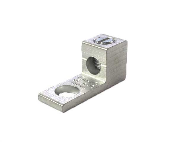
Adding one to the power supply takes care of bonding to the house ground system. Like you, I use a choke at my antenna feed points where things change to coaxial cable, although I just use a series of snap on ferrites to do that, not anything fancy. After all this, the only ferrite I have in my station is a single ferrite snap on where my microphone goes into my sound interface. The new inverted L is radiating into the house a bit (the dipole is up 65ft and is not an issue) and I wound up with a little audio RFI on 80M. No amount of grounding/bonding is going to fix RFI from radiated emissions! |
|
|
|
[#4]
To be honest my grounding at the bench looks like a rednecks checkbook but it works. I do have a 6ft ground rod. I am not however connected to the house ground except for the power plugs to the walls. All the chassis' are grounded with my ground, and typically all components have the ground wire secured to the chassis as well. No potential is seen, now with that said a friend in my area has never used a ground other than the 3 prong plug for his equipment and he has 8 band DXCC with 100w or less. Better to have something that is corectly setup, looking into a ground loop is confusing and a good learning experience. Fighting refl power (common mode current) is where a good ground will shine. Been slightly popped with a ic-746 on my first attempt to make a ssb contact. That was my first interduction to refl power.. Learning curve was quick...
Would add a pic but it would look like spaghetti and make no sense.. Prosise |
|
|
|
[#5]
Quoted:
Adding one to the power supply takes care of bonding to the house ground system. The other thing I discovered this morning, running around with a meter on set for continuity, is that I had a coax jumper between the KPA and the 7300 that was somehow a 40 ohm resistor on the ground shield. Just replaced that. Thanks for the advise -- I think bonding is a big issue for my shack, nothing is really connected to each other and I was counting on the coax shield to do the job -- but with a floating AC power supply, that's not happening at all! Guess I'll be digging a trench for the ground wire this weekend... |
|
|
|
[#6]
RF ground is a totally different animal than an electrical safety ground. An improperly designed and installed grounding system can be a lot worse than no grounding at all! I have seen this way too many times.
We have had a lot of threads about it. Just remember that a SINGLE POINT grounding is a MUST in a ham shack. You are having grounding loops that create common mode RF noise. Everything that enters your shack, must be grounded to a single point grounding. This includes all coax shields, all 120 VAC power wires and any control wiring. Your single point shack ground must be bonded to the house's ground with an uninsulated copper grounding conductor (I recommend - #4 gauge uninsulated solid copper), as short as possible. Here are a few links to read up on grounding: LINK LINK Another link although I don't agree with everything. He covers the basics very well though. Home depot rents trench diggers for about $40 for half a day. This is what I used. Also, look at adding a whole house surge protector at your main breaker panel. A decent surge protector can be bought for around $100. You will need one dual breaker opening to install a 30A dual pole breaker to feed your surge protector. It's a relatively cheap device that may save you a lot of headache in the future. I installed a $1,100 Zone Defender Plus at my house to be safe. My shack has a separate 200A feed and both meters are connected to a large step-down transformer on my property. The antenna tower is way above the trees and I'm not taking any chances. I also disconnect everything in my shack when I'm not operating. So far it's been ok and the noise level at the shack is way below S1 on 20-10m bands and at S1 or less on 40 meters. |
|
|
|
[#7]
These probably won't show up if I try to embed them but I did connect probably a dozen ground rods and hook onto the house's grounding system
http://nullbits.foxxz.net/shackbuild |
|
|
|
[#8]
Quoted:
These probably won't show up if I try to embed them but I did connect probably a dozen ground rods and hook onto the house's grounding system http://nullbits.foxxz.net/shackbuild |
|
|
|
[#9]
Quoted:
Daaaaaamn. I looked at every picture. I think you win this thread so far! Quoted:
Quoted:
These probably won't show up if I try to embed them but I did connect probably a dozen ground rods and hook onto the house's grounding system http://nullbits.foxxz.net/shackbuild |
|
|
|
[#10]
I recently put up a 30 foot mast for my son and I to use with our 2m/70cm dual band base station antenna and a G5RV HF antenna. The only place that I could put the mast was on the back side of our house in the middle. The service delivery point for the AC power was on the left side of our house, 90 degrees opposite from the mast. I did a lot of research and asked a lot of questions. This is the grounding system that I came up with.
What I did was sink an 8 foot ground rod close to the mast. The mast is bonded to that ground rod. The coax lightning arrestors and coax braid are all bonded to that ground rod using a bus bar inside of a plastic box. A length of 6 AWG bare solid copper ground wire connects the bus bar to the ground rod. Another 6 AWG solid copper wire runs along the back side of the house from the ground rod to the corner, where its bonded to another 8 foot ground rod. Another piece of 6 AWG bare copper ground wire runs along the left side of the house from the ground rod on the corner to the AC service ground where it is bonded to the AC service ground rod. I didn't realize it, but the AC service ground rod is under the condensation drain outlet from our heat pump so the soil is always moist! Our radios and antenna tuner inside the shack are bonded to a bus bar, which is connected to the AC ground by a 2 AWG stranded copper ground wire I had left over from another project. The shack is just on the other side of the exterior wall from the AC service delivery point. For 6 AWG soft copper, look on eBay. I was able to buy 100 feet pretty cheap. |
|
|
|
[#11]
seek2, here's my 2010 thread on this topic. Most of the pics were lost when Comcast stopped hosting several years ago. You may get some ideas, anyway. ARCHIVED THREAD - Station Grounding / Lightning Protection Pic Thread
More recent pics from a 2015 upgrade... BD's KF7P Cable Entrance Panel |
|
|
|
[#12]
sigh
This is making me think I need to re-route those nice short runs from my VHF/UHF+ antennas that sneak in though the attic vents to go around the entire perimeter of the house so they all enter in one grounded place. (I do have ground on those antennas at point of entry right now.) That's going to change the run to my discone from ~ 75' to probably 125'. So much loss! At least the HF is comparatively easy, though I can't tie the station ground into it easily (and I really can't do a NEC compliant run.) The other thing I'm wondering about is I've got security cameras with ethernet wiring, and they're on the same network as the radios and computers. I can't see running them to a single point entry, though I could see making a single point ground block for them -- but inside the house. Outside they're not grounded. |
|
|
|
[#13]
Quoted:
seek2, here's my 2010 thread on this topic. Most of the pics were lost when Comcast stopped hosting several years ago. You may get some ideas, anyway. ARCHIVED THREAD - Station Grounding / Lightning Protection Pic Thread More recent pics from a 2015 upgrade... BD's KF7P Cable Entrance Panel |
|
|
|
[#14]
Quoted:
lol, I went to the K7FP website and they're using your station to advertise the panel! |
|
|
|
[#15]
Quoted:
sigh This is making me think I need to re-route those nice short runs from my VHF/UHF+ antennas that sneak in though the attic vents to go around the entire perimeter of the house so they all enter in one grounded place. (I do have ground on those antennas at point of entry right now.) That's going to change the run to my discone from ~ 75' to probably 125'. So much loss! At least the HF is comparatively easy, though I can't tie the station ground into it easily (and I really can't do a NEC compliant run.) The other thing I'm wondering about is I've got security cameras with ethernet wiring, and they're on the same network as the radios and computers. I can't see running them to a single point entry, though I could see making a single point ground block for them -- but inside the house. Outside they're not grounded. If it works, you win, no fuss, no muss, and you did it in a few hours. If it doesn't then you can start in with the NEC compliant shit, trenching, UFER grounds and whatever other complexities you think you need. The only wrinkle in this plan is the power supply with the floating chassis. You are going to need to go inside that thing and, in a safe manner, fix that, or at least bring out a ground wire to bond to. What the hell kind of supply is that, anyway? |
|
|
|
[#16]
Quoted:
The only wrinkle in this plan is the power supply with the floating chassis. You are going to need to go inside that thing and, in a safe manner, fix that, or at least bring out a ground wire to bond to. What the hell kind of supply is that, anyway? The strange thing is I moved a bunch of cables and jumpers around today (I found one of my coax jumpers seem to have a pretty high resistance on the ground shield) and now it's showing as grounded, but I think it's getting there through some other pathway, e.g a downstream device is providing the ground via a connection to the DC negative supply. It also doesn't have any kind of ground lug on it, just a normal 3-prong power cable and nothing else. I've seen so many goofy readings (and heard some kind of ground currents when the continuity buzzer is going) I think the solution is just ground all the things per the bus bars suggested and then revisit the problem. I think last week when I inserted the choke, it wasn't the choke that fixed the problem, but bumping a cable that got un-bumped when I installed the 7300. |
|
|
|
[#17]
seek2, I opened up one of my Samlex power supplies and grounded it directly to my single point grounding bus under my operating desk. That had a particularly good pic that was lost!
 Samlex SEC 1223 power supply grounding Samlex SEC 1223 power supply grounding
|
|
|
|
[#18]
Bonding a Powerwerx power supply is no problem. I have a Powerwerx SPS-30DM and here is how I do it:
|
|
|
|
[#19]
Quoted:
It's the PowerWerx SS-30DV. The strange thing is I moved a bunch of cables and jumpers around today (I found one of my coax jumpers seem to have a pretty high resistance on the ground shield) and now it's showing as grounded, but I think it's getting there through some other pathway, e.g a downstream device is providing the ground via a connection to the DC negative supply. It also doesn't have any kind of ground lug on it, just a normal 3-prong power cable and nothing else. I've seen so many goofy readings (and heard some kind of ground currents when the continuity buzzer is going) I think the solution is just ground all the things per the bus bars suggested and then revisit the problem. I think last week when I inserted the choke, it wasn't the choke that fixed the problem, but bumping a cable that got un-bumped when I installed the 7300. Also, you only need an RF choke at the antenna's feedpoint. Installing one at the amp output will not really accomplish much. Again, beware of creating ground loops! DX Engineering sells a relatively inexpensive coax entrance grounding panel. It works well if you only have a few antennas. This is what I used and so far it's been working very well. I used Polyphaser coax protectors (commonly used in many commercial installations). They are rated for full legal limit and up to 500 Mhz. So far they survived numerous lightning strikes nearby. This is the only picture I could find: 
|
|
|
|
[#20]
I ground my 40 foot fold over mast to a ground rod with #1 stranded wire
that's it none of my radios , power supplies or my tuner even have ground wires on them. The only ground is the 3 prong equipment ground on the plug. I dont even have a ground bus. It does not seem to be an issue. I still dont get how if you ground the coax shield how is it supposed to radiate the other half of the dipole. So I dont ground it,but I have resonant dipole antennas. |
|
|
|
[#21]
Quoted:
I ground my 40 foot fold over mast to a ground rod with #1 stranded wire that's it none of my radios , power supplies or my tuner even have ground wires on them. The only ground is the 3 prong equipment ground on the plug. I dont even have a ground bus. It does not seem to be an issue. I still dont get how if you ground the coax shield how is it supposed to radiate the other half of the dipole. So I dont ground it,but I have resonant dipole antennas. when I did even the simplest grounding test, they completely went away, to the point I could run QRO where the problems popped up out at the antenna/tuner rather than in the shack. Anyone remember the name of that magic do-it-all coax that was both low loss and super flexible (like a flex version of LMR400)? I think my plan will be to pull the runs on my VHF antennas, and run everything to a panel on the side of my garage nearest my office/shack, ground it all there and then run it into the rafters and back down. It'll make long runs but I've had enough lightning scares (replaced routers and modems several times) and now this 20M issue, I think I've had my come-to-Jesus moment on grounds. |
|
|
|
[#22]
I bond everything including the computer to a copper bar that connects out to a ground rod.
Where my feedline comes into the shack I also have a 1:1 Isolation balun (double UHF connectors). All my TX antennas connect out at the tower via remote switch and come into the shack via 7/8 hard line. Probably wrong but works for me. |
|
|
|
[#23]
If I run a separate ground wire to a single point ground from each piece (radio, tuner, amp, etc) that are connected to each other by coax, wouldn't it create a possible ground loop situation since they are already grounded to each other by the coax shield? Wouldn't it be better to just ground the tuner to eliminate possible ground loops?
|
|
|
|
[#24]
Quoted:
If I run a separate ground wire to a single point ground from each piece (radio, tuner, amp, etc) that are connected to each other by coax, wouldn't it create a possible ground loop situation since they are already grounded to each other by the coax shield? Wouldn't it be better to just ground the tuner to eliminate possible ground loops? See here |
|
|
|
[#25]
Quoted:
From my reading, the fact that it's a single point ground is what makes the difference at RF frequencies as it provides a low-impedance route to ground and because all the equipment is at the same ground potential, no current flows -- without the single-point aspect, the ground potential varies and current does flow. See here |
|
|
|
[#26]
Quoted:
Anyone remember the name of that magic do-it-all coax that was both low loss and super flexible (like a flex version of LMR400)? |
|
|
|
[#27]
Seek2,
I am far from an expert ( I do have an EE degree ) but since your problem seems to be only on 20 meters and power related, I would look at the coax and the antenna being used for 20 meters. What type of antenna? Does it have a current balun at the antenna feed point? How long is the coax and what type is it? Have you checked the coax loss? It might be a non-resonant antenna and a coax length that is resonant without a current balun or a bad balun or a bad coax. If 20m is your only problem then it looks frequency specific. I dont think a ground problem is going to be freq specific. If you have RF in the shack due to a grounding issue I would think it would be all rf freqs not just 20 meters. I think it is more likely a poor connection in the antenna, a faulty current balun, ( ir you dont have one ) and or a coax problem either the coax is radiating due to a problem above or the coax has been compromised or it may even be a multiple of wavelength. What I would do. measure coax loss inspect antenna connections for breaks or corrosion add some feet of coax check all connections inspect the coax for breaks, pinches, bends, etc Try changing the coax completely just my 2 cents |
|
|
|
[#28]
Quoted:
If I run a separate ground wire to a single point ground from each piece (radio, tuner, amp, etc) that are connected to each other by coax, wouldn't it create a possible ground loop situation since they are already grounded to each other by the coax shield? Wouldn't it be better to just ground the tuner to eliminate possible ground loops? I'm an EE and work with industrial automation most of the time. Sometimes I have to design low and medium power systems as well. You would not believe how many times i had to fly across the country to troubleshoot mysterious intermittent problems with process control systems, caused by grounding loops. 4-20 mA analog control circuits are very common in industrial controls. Unfortunately, many electricians and even plant engineers don't have a good understanding of proper grounding principles. They would add an analog control link and all of the sudden they have issues with another device, unrelated to the one they just worked on. For example, a shield on a shielded analog cable should only be terminated to ground on one end. They'd terminate it on both ends and create grounding loops that may cause issues several months later. Common mode noise is another "animal" that can be very tricky. I have always carried a few dozen on "snap-on" RF chokes and installed them on analog links when I suspected this kind of a problem. This is why a lot of times, no ground can be better than improperly designed and installed ground. At work, I never counted on electrical contractors to know proper grounding principles and had my designers (CAD guys) specify every little detail of grounding, in all of our drawings. Many contractor electricians told me that they simply never paid that much attention to grounding in their previous projects. They called it good as long as things were connected to ground, for electrical safety. I have seen guys spend a lot of efforts to ground everything in their shack to only find out that nothing works right and they have all kinds of noise in their TX audio and RX on all frequencies. Simply disconnecting all the grounding contraptions fixed the problem. A closer look revealed multiple grounding loops and several grounding rods not bonded together. Most of the time doing it right by creating a single point ground system, got rid of noise and tuning problems. Sometimes it takes some trial and error to find out what works best for that particular setup. As for tuning and SWR issues, altering coax length often greatly improved the situation. |
|
|
|
[#29]
This is all very interesting, but I'd recommend looking for horses not zebras, first.
Do the simple things as a first step. If you have no grounding or bonding, add grounding and bonding. Obviously try to approximate the best "single point ground" you can. Obviously try to bond everything in the shack that touches your radio, amp or tuner in any way (power meters, PC's, the works). Make BIG changes looking for obvious differences, e.g. second story shack, disconnect the wire to the ground rod that's far away. Only after doing the simple stuff then start to consider the more complex and esoteric stuff. Two personal cases in point: a) My station would go ape-sh*t when running Olivia on 40M. I tried all kinds of crazy stuff, ferrites up the wazoo, changing feedline lengths, baluns, etc. After a few weeks I finally tracked it down to a broken shield on my PTT line. RF was getting into the PTT input and causing havoc. While this problem itself was sort of a zebra, I was able to undo all of the other crazy zebra stuff and was fine. b) Literally just this week I had RFI on audio for the first time in years. Only on 80M. The only change to the station was transmitting on the new inverted L. Digitally sourced audio coming over virtual audio cable connections was fine. That meant I could limit my investigations to the microphone wiring. A single ferrite on the mic cable did the trick. Again, horses, not zebras. Absolutely no requirement to change feedlines, baluns, isolators, grounding and bonding, use coax as ground lines, or any other crazy stuff. Don't like zebras? Use Occam's Razor, then, instead |
|
|
|
[#30]
Quoted:
This is all very interesting, but I'd recommend looking for horses not zebras, first. Do the simple things as a first step. If you have no grounding or bonding, add grounding and bonding. Obviously try to approximate the best "single point ground" you can. Obviously try to bond everything in the shack that touches your radio, amp or tuner in any way (power meters, PC's, the works). Make BIG changes looking for obvious differences, e.g. second story shack, disconnect the wire to the ground rod that's far away. Only after doing the simple stuff then start to consider the more complex and esoteric stuff. Two personal cases in point: a) My station would go ape-sh*t when running Olivia on 40M. I tried all kinds of crazy stuff, ferrites up the wazoo, changing feedline lengths, baluns, etc. After a few weeks I finally tracked it down to a broken shield on my PTT line. RF was getting into the PTT input and causing havoc. While this problem itself was sort of a zebra, I was able to undo all of the other crazy zebra stuff and was fine. b) Literally just this week I had RFI on audio for the first time in years. Only on 80M. The only change to the station was transmitting on the new inverted L. Digitally sourced audio coming over virtual audio cable connections was fine. That meant I could limit my investigations to the microphone wiring. A single ferrite on the mic cable did the trick. Again, horses, not zebras. Absolutely no requirement to change feedlines, baluns, isolators, grounding and bonding, use coax as ground lines, or any other crazy stuff. Don't like zebras? Use Occam's Razor, then, instead 
|
|
|
|
[#31]
Time for an update. So over the last couple days I've been digging into this more.
For context, I've had some kind of RF in the shack problems since the beginning, it's worst on 20M, but it's present on all bands. It's one the reasons I never run the KPA anywhere near its full ratings. I can run 150W, 200W tops on 40M, and less than that on other bands before things just start to get really wonky. On 20M even 100W is a problem -- I usually lose my trackpad first. (For the record, that trackpad is wired and has no fewer than 4 ferrites on the cable.) During the nets I switch to a wireless mouse as a backup. Let's start with the basics, which is just having DC continuity between everything. When I first started, with everything hooked up, the coax shield from the antenna to the ground pin of a nearby electrical socket measured as an open circuit (mostly, there's actually a slight AC voltage, which you might expect, and I measured current at 40 uA or so flowing. That made the ohm meter go a little crazy.) I started walking step by step from the antenna connector inside the shack through each jumper and piece of equipment. My setup is a little goofy due to doing power injection: Antenna->tuner->coax->bulkhead->jumper->12V DC injector->polyphaser->SWR->KPA500->IC 7300 (and yeah, I know the polyphaser is going to provide very little protection, it works as a DC block and at least drains some static.) To make life easier I just tried to measure resistance from the antenna coax to the ground of the 7300, and when I started I was seeing anything from 50 ohms to several K ohms. I found a couple of (what I thought at the time) bad jumpers, where I was reading 50-150 ohms end to end, replaced those. I could get the total resistance down to under 5 ohms, which still seemed high. Then I went to bed, woke up, and the resistance is up again, over 60 ohms. Repeat process, more bad jumpers? So I started testing the jumper at the shield, and they're OK. But when screwed onto equipment, I'm seeing pretty high resistance. I started to suspect there was something more going on here than just a bad jumper. I thought it might be possible the shield and PL-259s weren't making a solid electrical connection, so on a lark I took some penetrox on a q-tip and applied small amounts on all the mating surfaces of each jumper. One by one the resistance starts falling, until I got 0 ohm readings from the antenna coax shield to the ground terminal of the IC-7300. Interestingly, at this point I also got a near 0 ohm reading from the coax shield to the outlet ground, as well. I'm fairly sure that's happening via the KPA500. So phase one -- there's obviously a lot of oxide-induced resistance in jumper connections! That's fixed. Fired up 20M, and switched in the amp and... improvement, but not much. So phase 2... bonding equipment. Made up a few short pigtails with ring terminals, and wired everything together -- but no ground connection. As you'd expect, no change, since we already have good connections via the jumpers and coax now. A few days ago I did a simple connection from the coax shield to the electrical outlet ground, and saw a big improvement. I did the same, and saw barely any improvement -- and then realized I had excess wire that was coiled in the ground wire this try. Cut that off and noticable improvement, but still far from perfect. But that change with v. without the coil was a big hint that I not only have a ground bonding problem, but a ground bonding impedance problem. At this point, I think I have/had a collection of problems -- a lot of bad connections in the shack, which are now fixed, but pretty much everything points at be needing a low-impedance connection between the antenna ground and the house electrical ground. Plenty of literature out there talks about that, and it's probably time to stop ignoring it. One other tidbit -- I tried one other thing. My desktop system is plugged into a very robust UPS, and everything runs off of it. I dropped all hard connections to it and pulled the plug, which should in theory make it floating. Still have the RFI problems. For now I'll live with it, but once it's cooler this fall, I suspect I'll be putting in a ground system on par with BigDaddy's, e.g. do a trench and lay down a copper strap from my house's ground around to the shack (and probably further.) I'm not convinced it will cure this issue, but it can't hurt. |
|
|
|
[#32]
Following.
|
|
|
|
[#33]
Quoted:
Yes, this may cause a problem. Grounding loops can be very tricky, especially in complex systems that were installed long time ago. It's often nearly impossible to trace all grounding lines and cable shield connections/terminations. A lot of times the only way to fix it is by trial and error. I'm an EE and work with industrial automation most of the time. Sometimes I have to design low and medium power systems as well. You would not believe how many times i had to fly across the country to troubleshoot mysterious intermittent problems with process control systems, caused by grounding loops. 4-20 mA analog control circuits are very common in industrial controls. Unfortunately, many electricians and even plant engineers don't have a good understanding of proper grounding principles. They would add an analog control link and all of the sudden they have issues with another device, unrelated to the one they just worked on. For example, a shield on a shielded analog cable should only be terminated to ground on one end. They'd terminate it on both ends and create grounding loops that may cause issues several months later. Common mode noise is another "animal" that can be very tricky. I have always carried a few dozen on "snap-on" RF chokes and installed them on analog links when I suspected this kind of a problem. This is why a lot of times, no ground can be better than improperly designed and installed ground. At work, I never counted on electrical contractors to know proper grounding principles and had my designers (CAD guys) specify every little detail of grounding, in all of our drawings. Many contractor electricians told me that they simply never paid that much attention to grounding in their previous projects. They called it good as long as things were connected to ground, for electrical safety. I have seen guys spend a lot of efforts to ground everything in their shack to only find out that nothing works right and they have all kinds of noise in their TX audio and RX on all frequencies. Simply disconnecting all the grounding contraptions fixed the problem. A closer look revealed multiple grounding loops and several grounding rods not bonded together. Most of the time doing it right by creating a single point ground system, got rid of noise and tuning problems. Sometimes it takes some trial and error to find out what works best for that particular setup. As for tuning and SWR issues, altering coax length often greatly improved the situation. Quoted:
Quoted:
If I run a separate ground wire to a single point ground from each piece (radio, tuner, amp, etc) that are connected to each other by coax, wouldn't it create a possible ground loop situation since they are already grounded to each other by the coax shield? Wouldn't it be better to just ground the tuner to eliminate possible ground loops? I'm an EE and work with industrial automation most of the time. Sometimes I have to design low and medium power systems as well. You would not believe how many times i had to fly across the country to troubleshoot mysterious intermittent problems with process control systems, caused by grounding loops. 4-20 mA analog control circuits are very common in industrial controls. Unfortunately, many electricians and even plant engineers don't have a good understanding of proper grounding principles. They would add an analog control link and all of the sudden they have issues with another device, unrelated to the one they just worked on. For example, a shield on a shielded analog cable should only be terminated to ground on one end. They'd terminate it on both ends and create grounding loops that may cause issues several months later. Common mode noise is another "animal" that can be very tricky. I have always carried a few dozen on "snap-on" RF chokes and installed them on analog links when I suspected this kind of a problem. This is why a lot of times, no ground can be better than improperly designed and installed ground. At work, I never counted on electrical contractors to know proper grounding principles and had my designers (CAD guys) specify every little detail of grounding, in all of our drawings. Many contractor electricians told me that they simply never paid that much attention to grounding in their previous projects. They called it good as long as things were connected to ground, for electrical safety. I have seen guys spend a lot of efforts to ground everything in their shack to only find out that nothing works right and they have all kinds of noise in their TX audio and RX on all frequencies. Simply disconnecting all the grounding contraptions fixed the problem. A closer look revealed multiple grounding loops and several grounding rods not bonded together. Most of the time doing it right by creating a single point ground system, got rid of noise and tuning problems. Sometimes it takes some trial and error to find out what works best for that particular setup. As for tuning and SWR issues, altering coax length often greatly improved the situation. |
|
|
|
[#34]
I had another idea late this evening.
So I pondered, with all the oxide issues with the jumpers... could there be issues with my actual electrical ground as well? Got out the ohm meter. The resistance between grounds on the outlets that supply my computer and the outlet that supplies the transceiver and amplifier... 303 Ohms. That ain't right. Guess I'll be opening up the main electric panel tomorrow. |
|
|
|
[#35]
Got any Chinese drywall?
|
|
|
|
[#36]
Quoted:
I had another idea late this evening. So I pondered, with all the oxide issues with the jumpers... could there be issues with my actual electrical ground as well? Got out the ohm meter. The resistance between grounds on the outlets that supply my computer and the outlet that supplies the transceiver and amplifier... 303 Ohms. That ain't right. Guess I'll be opening up the main electric panel tomorrow. FYI: Neutral must be bonded to ground in the main breaker box. So, all measurements between all the neutral wires and the ground should read very low resistance. Have you thought about installing a whole house surge protector? Lowes sells small surge protectors that fit into a double slot in a breaker panel. They cost only around $60. It's not as good as a dedicated surge protector but it's better than nothing at all. |
|
|
|
[#37]
Quoted:
What voltage do you read from neutral to ground and from ground to "hot"? FYI: Neutral must be bonded to ground in the main breaker box. So, all measurements between all the neutral wires and the ground should read very low resistance. Have you thought about installing a whole house surge protector? Lowes sells small surge protectors that fit into a double slot in a breaker panel. They cost only around $60. It's not as good as a dedicated surge protector but it's better than nothing at all. I know they should be bonded, which is why I was surprised by the ground-to-ground measurement of 300 Ohms. My panel is ancient (mid 70s) and I'm sure the bus bars haven't been touched since it was installed. My plan is to pull the main breaker and torque all the ground screws on the bus bar and see if the ground- to-ground readings change. I doubt any off-the-shelf stuff from Lowes will fit this panel. My house was built by a contractor using cast-off and rejected materials, and the panel is so obscure when the AC breaker melted my HVAC guy had to special order the replacement breaker. It's not the usual Square D stuff. |
|
|
 Win a FREE Membership!
Sign up for the ARFCOM weekly newsletter and be entered to win a free ARFCOM membership. One new winner* is announced every week!
You will receive an email every Friday morning featuring the latest chatter from the hottest topics, breaking news surrounding legislation, as well as exclusive deals only available to ARFCOM email subscribers.

AR15.COM is the world's largest firearm community and is a gathering place for firearm enthusiasts of all types.
From hunters and military members, to competition shooters and general firearm enthusiasts, we welcome anyone who values and respects the way of the firearm.

Subscribe to our monthly Newsletter to receive firearm news, product discounts from your favorite Industry Partners, and more.
Copyright © 1996-2024 AR15.COM LLC. All Rights Reserved.
Any use of this content without express written consent is prohibited.
AR15.Com reserves the right to overwrite or replace any affiliate, commercial, or monetizable links, posted by users, with our own.