|
Posted: 9/21/2017 1:04:15 AM EDT
Specifically, for inverter generator models that normally only produce 120VAC when paralleled?
Seems like it would be pretty easy to invert the synchronization signal to one of the two generators, so that it produced AC power 180 degrees out of phase with the other one. ETA: Obviously, the original parallel AC output connection between both generators would also have to modified, in order to avoid certain...um, unpleasantries... 
|
|
|
|
[#1]
Quoted:
Specifically, for inverter generator models that normally only produce 120VAC when paralleled? Seems like it would be pretty easy to invert the synchronization signal to one of the two generators, so that it produced AC power 180 degrees out of phase with the other one. Some years ago someone had a YouTube video of a new product and it was discussed here quite a bit... We were all trying to figure out how it worked... Apparently the device was in a little NEMA box, but never heard of it again. |
|
|
|
[#2]
|
|
|
|
[#3]
|
|
|
|
[#4]
That video seems like an overly complex solution(?) to a pretty basic task:
1. Take the synchronization signal from one generator, 2. Use an op-amp to produce an exact duplicate of it that is 180 degrees out of phase with the original, 3. Feed this inverted signal to the other generator, and 4. Re-connect the AC outputs of both generators so that they supply 120 VAC between either generator's LINE and NEUTRAL wires, and 240 VAC between both generators' LINE connections. Am I overlooking something important here? |
|
|
|
[#5]
Quoted:
That video seems like an overly complex solution(?) to a pretty basic task: 1. Take the synchronization signal from one generator, 2. Use an op-amp to produce an exact duplicate of it that is 180 degrees out of phase with the original, 3. Feed this inverted signal to the other generator, and 4. Re-connect the AC outputs of both generators so that they supply 120 VAC between either generator's LINE and NEUTRAL wires, and 240 VAC between both generators' LINE connections. Am I overlooking something important here? Didn't have 2 2000's in 2009, now I do, so -maybe... That info would likely have provided the answer. OTOH, maybe Honda has designed the system to simply lock up to any AC phase angle the opposite genny sees. Maybe each genny does it simultaneously and autonomously, I have no idea how that could be done, having thought abt it some. |
|
|
|
[#6]
Is the procedure to hook two together require that they first be connected and then started?
Or can they both be running and then connected -- |
|
|
|
[#7]
I'm guessing that the kit is connected before the generators are started.
That just makes more sense than having to reconnect the kit every time you restart the generators. Champion provides schematics for their inverter models - Here's the 2000i model: 
Note that the "Parallel Terminal" (highlighted in blue) is connected directly to the LINE and NEUTRAL pins on the AC output receptacle. Presumably, any line frequency synchronization signals or data are sent on the 4-pin "Parallel Operation Control" receptacle (highlighted in red) - 2 pins of which are probably just carrying low-voltage DC power from the "Parallel Power Unit". |
|
|
|
[#8]
Quoted:
I'm guessing that the kit is connected before the generators are started. That just makes more sense than having to reconnect the kit every time you restart the generators. Champion provides schematics for their inverter models - Here's the 2000i model: http://www.skibane.com/Champion_2000i_Schem.jpg Note that the "Parallel Terminal" (highlighted in blue) is connected directly to the LINE and NEUTRAL pins on the AC output receptacle. Presumably, any line frequency synchronization signals or data are sent on the 4-pin "Parallel Operation Control" receptacle (highlighted in red) - 2 pins of which are probably just carrying low-voltage DC power from the "Parallel Power Unit". I did know from looking at the diagrams that the parallel binding posts were paralleled with the AC outlets --and think I commented here [and elsewhere] several times that there was no need to buy the $49 or whatever kit, just wire the two gennys together. I'm not aware that to sync two Honda gennys together there's any need for more than connecting the outlets together via their fancy banana plug kit [or a homemade one]. Just saw you were talking about the Champion and not the Honda regarding the schematic. Maybe that's how Champion got around any patents Honda may have had. I do now recall seeing some inverter Champion's in the box stores with the additional interconnect synching connector and wondering abt their system. |
|
|
|
[#9]
Jury-rigging or jury tampering is against the law. Just sayin
|
|
|
|
[#10]
This would be awesome.
I have a pair of Yamaha EF2000's that I'd love to use to power my mini-splits or furnace during an emergency. |
|
|
|
[#11]
Quoted:
That video seems like an overly complex solution(?) to a pretty basic task: 1. Take the synchronization signal from one generator, 2. Use an op-amp to produce an exact duplicate of it that is 180 degrees out of phase with the original, 3. Feed this inverted signal to the other generator, and 4. Re-connect the AC outputs of both generators so that they supply 120 VAC between either generator's LINE and NEUTRAL wires, and 240 VAC between both generators' LINE connections. Am I overlooking something important here? Other than that, I don't see why inverting/reversing the AC power just on a signal line wouldn't work. |
|
|
|
[#12]
tag again
|
|
|
|
[#13]
Quoted:
The concern is that if the 120 output is tied directly to the "sync signal" there is going to be issues. You will have to isolate that "sync line" from the "AC line" before connecting them. 
|
|
|
|
[#14]
I'm wondering and would guess, that the Honda sync pulse modulates the AC power and might be a 'tone' at crossover of the sine, or an actual data packet.
Probably observable on a scope. Someone needs to do it and quit speculating...
|
|
|
|
[#15]
Paralleling/ synching will be difficult with these to get 240V / 180 degrees out. I had 2 EU3000 and always jumped A-B in plug. A EU type that could do 30-50 Amps would be nice but pricey.
|
|
|
|
[#16]
Quoted:
Apparently, on the EU2000i, that "sync" connection to the 120VAC output is made on the "Inverter Unit" circuit board itself. http://www.skibane.com/Honda EU2000i Schematic.jpg Quoted:
Apparently, on the EU2000i, that "sync" connection to the 120VAC output is made on the "Inverter Unit" circuit board itself. http://www.skibane.com/Honda EU2000i Schematic.jpg I would be more than willing to test this if I had 2 EU2000is and the circuits knowledge to do it right, but I don't have either. I would have tested it years ago when it was proposed but I didn't have them then either. I'm willing to help make this come to fruition if I can...
Quoted:
Paralleling/ synching will be difficult with these to get 240V / 180 degrees out. Are you following along with this conversation and have something valuable to add or are you just speculating that it will be difficult. The OP has proposed the exact same solution that I proposed in the thread several years ago but nobody has tried it yet. There was supposedly a guy that was going to have some cords made and do a group-buy in the above-linked thread but it got shut-down by mods as an unapproved group-buy. The idea isn't new or novel, and it's actually rather simple (if that's all there is to it). It just hasn't panned out that somebody with the desire also had the knowledge and capabilities so far. And if those 3 do occur, you can bet that it won't necessarily be marketed; UL-listings aren't cheap, among many other challenges for a very low-demand item. I think if one did figure it out they would be better served to sell a "DIY kit" with directions. FWIW, 180-degrees out of phase is the exact same thing as "opposite voltage". I would definitely agree with you if you said that about creating a sine-wave 120-degrees out of phase (like a 2nd leg of 3-phase), or any value other than 180 degrees out. But 180 degrees (and only 180-degrees) is very simple. |
|
|
|
[#17]
Quoted:
I'm wondering and would guess, that the Honda sync pulse modulates the AC power and might be a 'tone' at crossover of the sine, or an actual data packet. 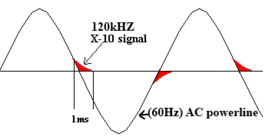
Looks like there might be different solutions for Champion (intercept and modify a signal on the parallel control connector), and for Honda & clones (intercept and modify a signal on the AC power output). I'll fire up a Champion 2000i this weekend to put a scope on the parallel control connector. Don't have any Honda inverter models to test. |
|
|
|
[#18]
Quoted:
Reminds me of the old X10 power line comm scheme. http://www.ee.ic.ac.uk/leon.zhang11/yr2proj/img/sinewave.png Looks like there might be different solutions for Champion (intercept and modify a signal on the parallel control connector), and for Honda & clones (intercept and modify a signal on the AC power output). I'll fire up a Champion 2000i this weekend to put a scope on the parallel control connector. Don't have any Honda inverter models to test. |
|
|
|
[#19]
Working on it now...
|
|
|
|
[#20]
Over in the current GD thread, Desert_AIP mentioned that the Hondas will work when paralleled with other brands of inverter generators - Which seems to imply that either (1.) they are self-synching (i.e., don't communicate with the other generator), or (2.) the clones have also cloned Honda's communication scheme.
Possibility (1.) doesn't seem very likely, since that would mean that you could even parallel a Honda inverter model with some ratty old Harbor Freight 2-stroke non-inverter generator...
|
|
|
|
[#21]
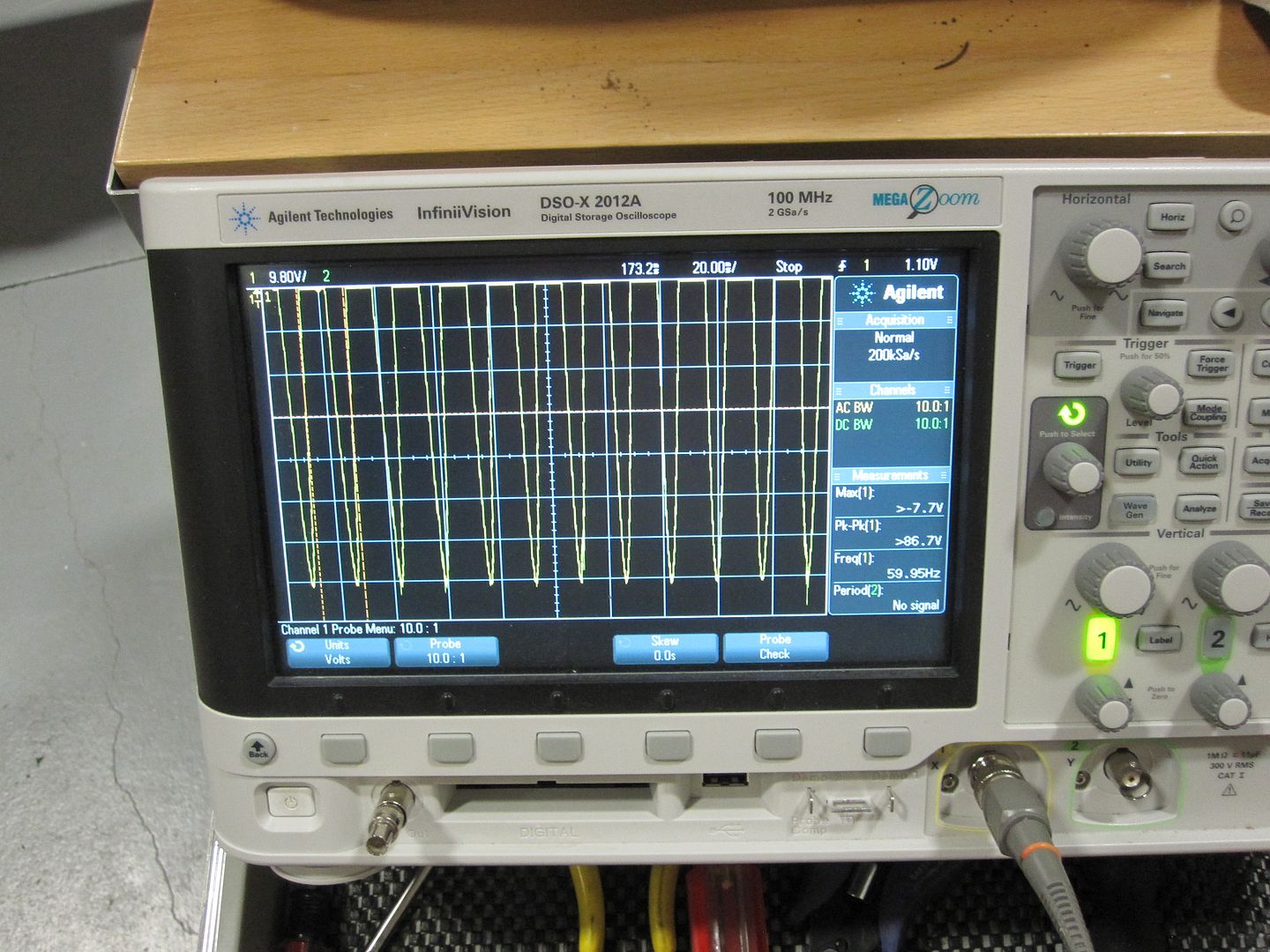
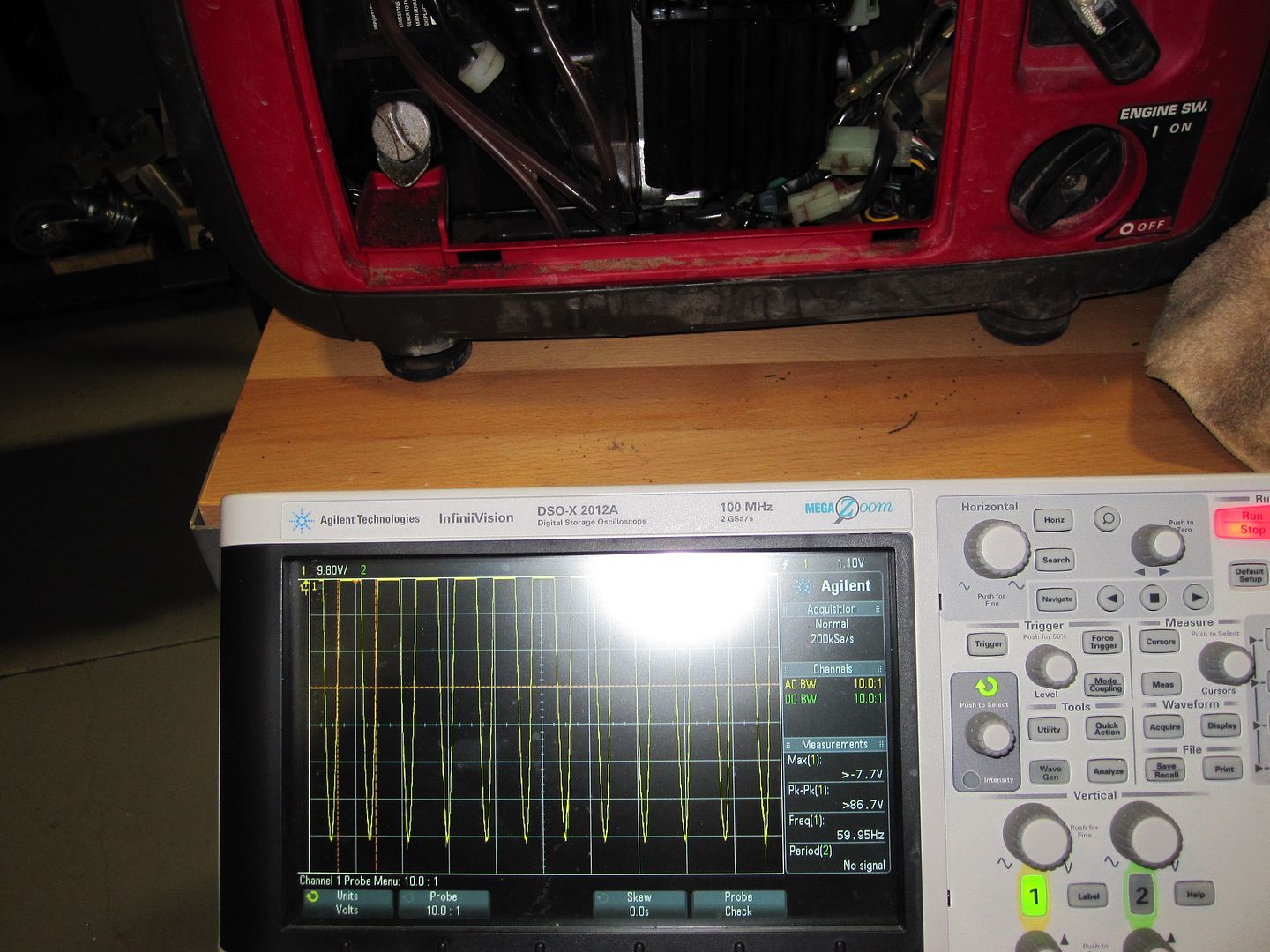
Scope traces.
On the 'negative side' there's some subtle but interesting pulses that are hard to see. Wonder how they are detected ---if they even are ---or are some artifact of the switching inverter. 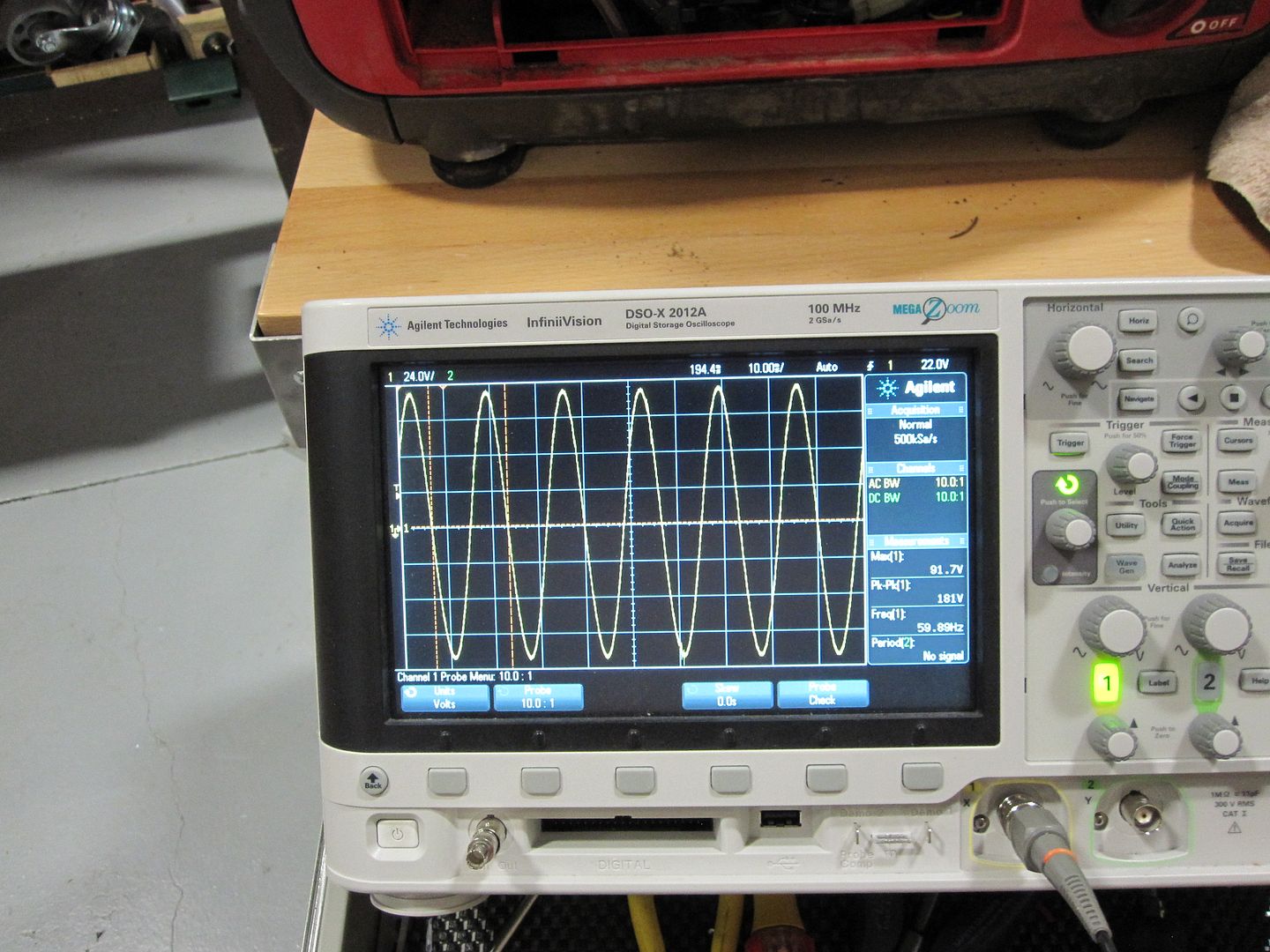
Visible on the 'negative' waveform, not on the 'positive'. Seem to have some consistent period. Not all negative pulses have them, want to think abt this before I scope it further. There seems to be some sort of pattern to the pulses on the negative waveforms using the horizontal 'stretching' capabilities of this scope and scrolling thru looking at each one. Looking for ideas... 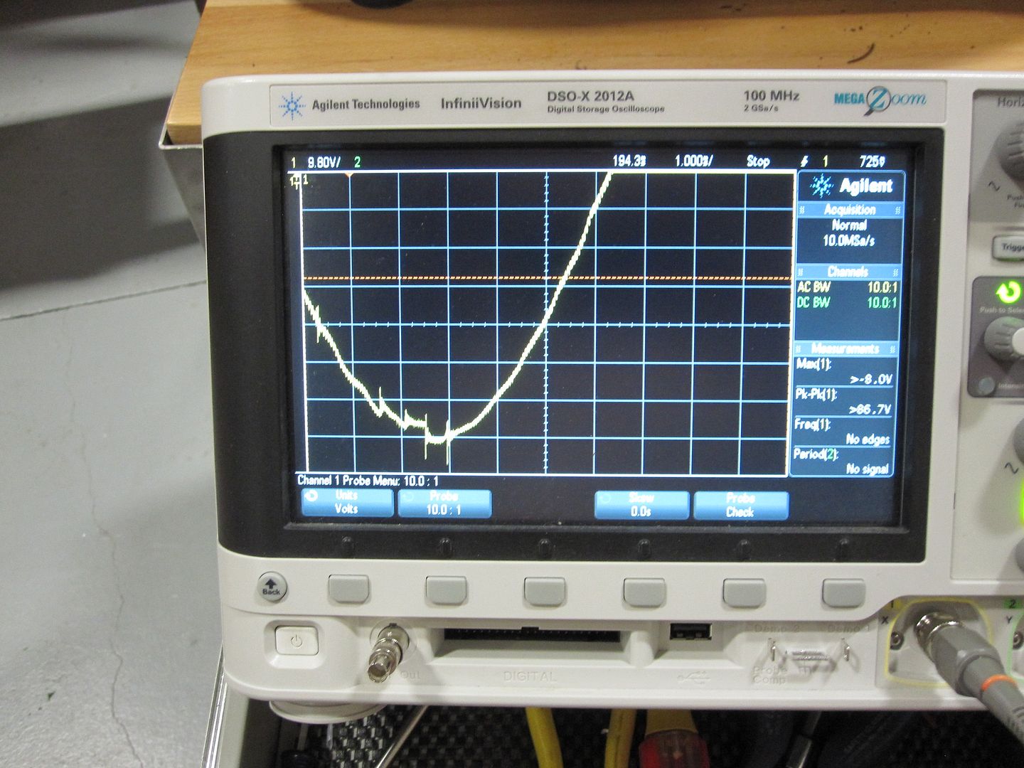
Had trouble with the carb and cleaned it repeatedly, still needs choke to run. No--- before the amateurs start screaming Bad Fuel, the fuel is and was fine.
It's the 'Cementing Silica' issue I've been pursuing and posting abt for years I think. This time the failing genny is down here in my shop with my resources, I studied the carb and finally think I know how to pin point the issue. Yes everything has been blown, all was clean -except some tiny orifices and an adjustment needle on the engine side of the throttle plate that I have to figure some way to evaluate.. These orifices and the adjustable jet are all connected to a small drilled supply passage from the front of the carb. Going to think abt how to precisely diagnose this ----without shot-gunning it. And without losing the symptom. You can see the small fuel filter I added -in the pix above, that stopped the previously -often- recurring 'cementing' issue for years -until now. This genny hasn't run for over a year... 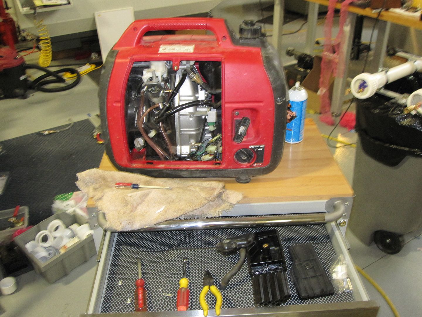
|
|
|
|
[#22]
PARover tried to link 2 of the little Harbor Freight gennys together, but missed the sync moment and fried @ least one of em, if not both. I think it's linked in the main Harbor Freight gen thread if he didn't just post it in there. This is after he got it to start on charcoal lighter fluid and run on rubbing alcohol.
|
|
|
|
[#23]
Quoted:
Scope traces. On the 'negative side' there's some subtle but interesting pulses that are hard to see. Wonder how they are detected ---if they even are ---or are some artifact of the switching inverter. http://i994.photobucket.com/albums/af66/expy37/IMG_0005_zpsn172qye8.jpg Visible on the 'negative' waveform, not on the 'positive'. Seem to have some consistent period. Not all negative pulses have them, want to think abt this before I scope it further. There seems to be some sort of pattern to the pulses on the negative waveforms using the horizontal 'stretching' capabilities of this scope and scrolling thru looking at each one. Embedding a "signal" in an AC power waveform at any spot other than the zero crossing points just seems strange to me - The ZCPs are the only spots in the waveform that aren't likely get distorted or buried in noise produced by whatever load the generator is powering. |
|
|
|
[#24]
Quoted:
What happens to them when you put a sizable electrical load on the generator? Will try. Embedding a "signal" in an AC power waveform at any spot other than the zero crossing points just seems strange to me - The ZCPs are the only spots in the waveform that aren't likely get distorted or buried in noise produced by whatever load the generator is powering. It might look like Honda is 'modulating' the varying PWM frequency by dropping pulses? I'll examine the waveform in much greater detail. If the Honda can sync to another -NON-Honda- genny, then there seems to be no reason it couldn't sync to the AC line, and could be tested by putting a suitable impedence between the sources, like a light bulb. I doubt if other mfgr's are going to add a Honda compatible synching feature to their gennys without making an issue out of it, the same for Honda, ---considering cost, potential customer issues, no purpose, and liability. |
|
|
|
[#25]
The scope is being powered by the genny to reduce 'noise' sources.
I think I have a way to evaluate the carb multiple fine orifice issue and maybe put this to rest. I think I have figured out a simple, PWM oscillator phase detection and locking scheme, that detects the AC output/phase from a 'master' connected and running genny, before turning on the 'phase locked' slave genny output, possibly a -'universal'- way, Honda might use, to synchronize, and I'll test it by trying to sync to the [master] AC mains later today. I'll have to make a suicide cord first. lol . |
|
|
|
[#26]
Quoted:If the Honda can sync to another -NON-Honda- genny, then there seems to be no reason it couldn't sync to the AC line, and could be tested by putting a suitable impedence between the sources, like a light bulb. Quoted:If the Honda can sync to another -NON-Honda- genny, then there seems to be no reason it couldn't sync to the AC line, and could be tested by putting a suitable impedence between the sources, like a light bulb. I doubt if other mfgr's are going to add a Honda compatible synching feature to their gennys without making an issue out of it, the same for Honda, ---considering cost, potential customer issues, no purpose, and liability. Honda's scheme works, so why go to the trouble of coming up with something else? |
|
|
|
[#27]
Ran the test---
Used a 125 watt clear IR reflector lamp with a nice long filament that's easy to see. Connected it in series to the Mains 120 hot leg and tied the neutrals together. Here's what happened.... With the lamp connected to the mains and genny, and the Honda NOT running, the lamp glowed at approx 20 watts brilliance. After starting the Honda, the internal inverter control logic seems to take a couple seconds to analyze what it is connected to --and the microprocessor synched to the mains AC ---and then the lamp dimmed to almost being extinguished, as the Honda matched phase/frequency to the 60 hertz mains. So, it took the inverter phase lock circuitry a couple seconds to 1/analyze, 2/lock, 3/produce, ---whatever power it decided to. Once the lock was accomplished, the Honda seemed to 'waste' some current for the 'sensing' process. Very little, I'd guess 10 watts, as evidenced by the barely glowing filament. My Honda powered the lamp independently, after the test, OK! Never was a concern actually... Next--- I don't know how the load is balanced between two or more connected gennys. Maybe the loads of each are encoded into the PWM steps as a means of communicating between each other, per the scope traces above. Maybe they don't try to balance load, altho that would seem to introduce some RPM instability. Important--- I expect that the loop bandwidth of the [likely crystal controlled] phase lock logic in the Honda is tight... It well may lock to another inverter genny that's within 1% or less frequency of the Honda. How power is balanced between a Honda and another brand genny ---is a question. Caution--- Connecting a Honda inverter genny to a poorly/mechanically regulated genny is likely going to make for some interesting effects. If anyone does it please stay close and take video! Any speculation based on this info? |
|
|
|
[#28]
Quoted:Once the lock was accomplished, the Honda seemed to 'waste' some current for the 'sensing' process. Very little, I'd guess 10 watts, as evidenced by the barely glowing filament. Quoted:Once the lock was accomplished, the Honda seemed to 'waste' some current for the 'sensing' process. Very little, I'd guess 10 watts, as evidenced by the barely glowing filament. After all, power flowing either direction will make the bulb glow just as bright! If your Honda has some sort of current-measuring ability, it may simply be supplying whatever voltage is necessary to keep that current flowing out of the generator, rather than into it. Maybe they don't try to balance load |
|
|
|
[#29]
Quoted:
It might have been contributing those 10 watts to your power grid, rather than dissipating them inside itself... After all, power flowing either direction will make the bulb glow just as bright! If your Honda has some sort of current-measuring ability, it may simply be supplying whatever voltage is necessary to keep that current flowing out of the generator, rather than into it. There are videos showing more than 2 Hondas being paralleled. Also, all Hondas connected in parallel don't have to be the same size - which implies that the load doesn't have to be balanced between them. Really should have said, to be more precise ---balanced in accordance with the % capability of each genny --or something like that... |
|
|
|
[#30]
Here's the "Parallel Operation Connector" pinout for the Champion 2000i -

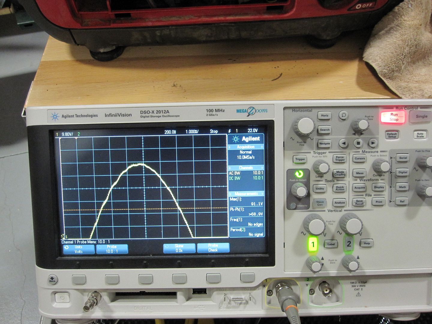
I have labeled the pins arbitrarily, for discussion purposes. Pins 2 and 3 are internally connected together, and are the signal ground connection. However, they are NOT connected to the generator's frame ground - They are isolated from it. The shell of the connector IS connected to the generator's frame ground. Whenever the generator is running, this is the waveform present on Pin 1, with respect to signal ground (Pin 2 or 3): 
Here's a close-up (ECO mode on, no load connected), which shows... 
A 60 Hz timing signal!!! Here's what it looks like with the ECO mode turned off (engine now running at full speed, but still without any load on it): 
Note that the timing hasn't changed, but the amplitude of the signal has increased from approx. 17.2 volts to approx. 25.6 volts. Here's what it looks like with a 1.2KW load added: 
Note that the amplitude has further increased, to approx. 27.6 volts. Finally, here's what Pin 4 looks like, with respect to signal ground (Pin 2 or 3): 
It doesn't get any more distinct when a load is present, or if ECO mode is turned off - Basically, it just looks to me like random switching noise, the most prominent of which is a 60 Hz spike. My guess is that this pin is the signal input to this generator, provided by Pin 1 on the other parallel-connected generator. |
|
|
|
[#31]
Interesting...
Looks like a good way to do the paralleling system. |
|
|
|
[#32]
For the Champion, seems like a sample-and-hold circuit would be the simplest way to produce a duplicate square wave that has the same amplitude as the original, delayed by 1/120th of a second:
1. Sample the Pin 1 voltage from Generator #1 while it's at full amplitude, 2. Start feeding the sampled voltage to Generator #2 as soon as the voltage from Generator #1 drops to approx. zero, 3. Stop feeding the sampled voltage as soon as some voltage from Generator #1 re-appears, 4. Repeat. Not sure about the best way to power the sample-and-hold circuit - The square wave signal present on Pin 1 might be capable of powering a very small DC/DC converter circuit without being loaded down too much. Otherwise, the converter circuit could be powered from one of the generator's 12VDC battery charger receptacles (although this receptacle is not present on all 2000i variants). Another option to get the required 30 VDC or so would be to use a tiny switcher connected to one of the generator's AC outputs. |
|
|
|
[#33]
After probably 20+ hours over the past 4 days of intense diagnosis of the "Failing to Run Correctly but Idles Fine" Honda 2000i issue...
I think I have the problem solved --and it drove me nuts. This issue can be expected more often since the genny fleet is aging... It wasn't a 'dirty' carb... Also, some info on the carb ---not many may know, tips for diagnostic/trouble shooting, what to expect on older units, what to stock if your Honda's availability is critical in an emergency, pictures, and ---maybe--- more. Will be in a new topic... |
|
|
 Win a FREE Membership!
Sign up for the ARFCOM weekly newsletter and be entered to win a free ARFCOM membership. One new winner* is announced every week!
You will receive an email every Friday morning featuring the latest chatter from the hottest topics, breaking news surrounding legislation, as well as exclusive deals only available to ARFCOM email subscribers.

AR15.COM is the world's largest firearm community and is a gathering place for firearm enthusiasts of all types.
From hunters and military members, to competition shooters and general firearm enthusiasts, we welcome anyone who values and respects the way of the firearm.

Subscribe to our monthly Newsletter to receive firearm news, product discounts from your favorite Industry Partners, and more.
Copyright © 1996-2024 AR15.COM LLC. All Rights Reserved.
Any use of this content without express written consent is prohibited.
AR15.Com reserves the right to overwrite or replace any affiliate, commercial, or monetizable links, posted by users, with our own.