|
Posted: 3/15/2021 1:59:10 PM EDT
The following footprints are of my CW signals on 2021-March-14 at about 04:00 to 04:20 UTC.
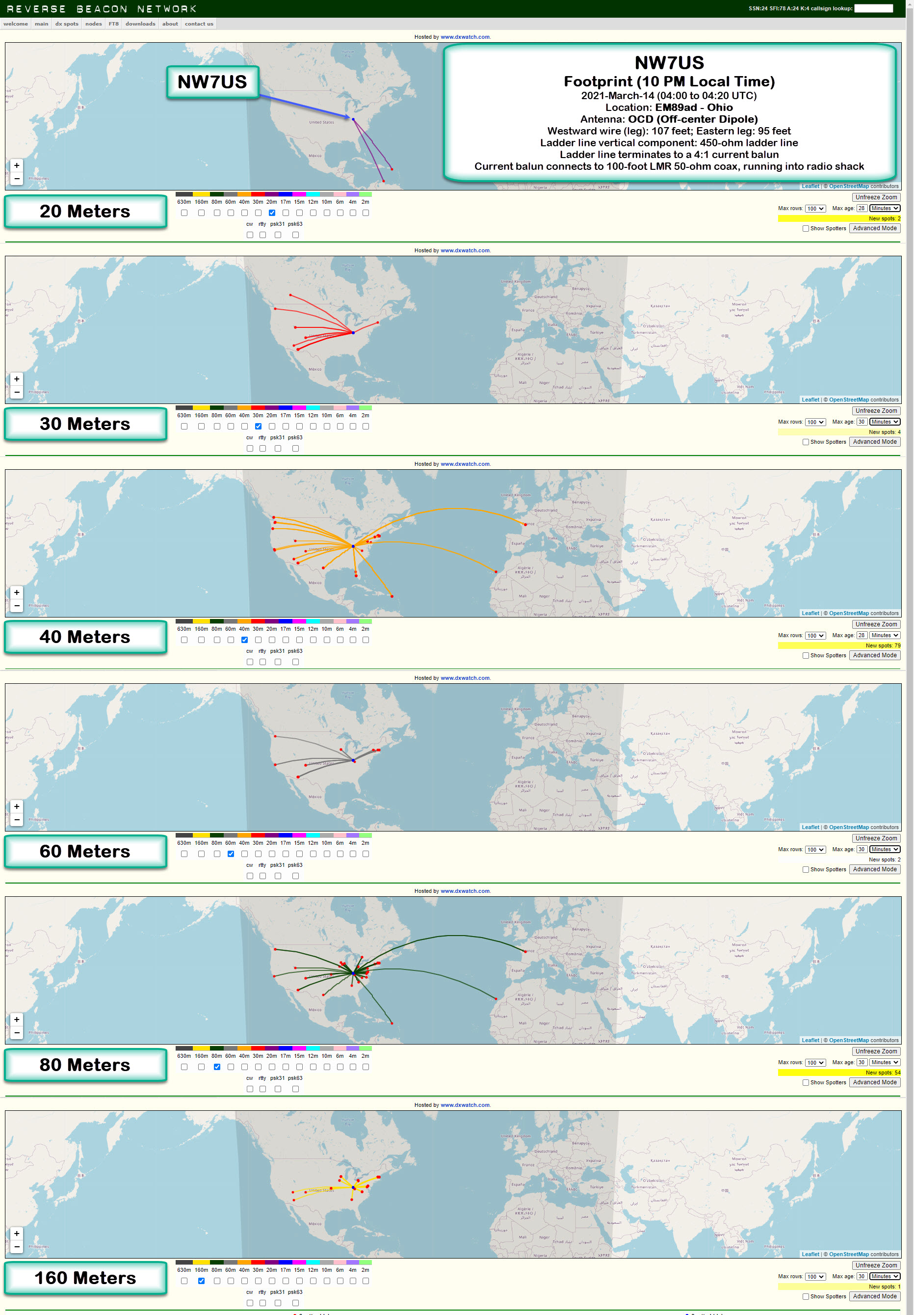 Location: EM89ad - Ohio Antenna: OCD (Off-center Dipole) Description of Antenna: This is an off-center dipole, with the two legs running East-West. The westward wire (leg) is approximately 107 feet in length, while the eastward leg is about 95 feet in length. This is fed with about 90 feet of 450-ohm ladder line, which is hanging directly below, vertically, the feed point which is 50 feet above the ground. The ladder line terminates (at the 12-feet-above-ground point) to a 4:1 current balun. This current balun connects to a 100-foot LMR 50-ohm coax, running into the radio shack where I use it to do these tests. I am transmitting a 100-watt CW signal using an Icom IC-7610. I show the 20-, 30-, 40-, 60-, 80-, and 160-Meter band footprints. 73 de NW7USdit dit .. |
|
|
|
[#1]
Looks like it is working well for you. May I ask, what software are you using to make these and how does it discriminate your signal from all other signals?
|
|
|
|
[#2]
Quoted: Looks like it is working well for you. May I ask, what software are you using to make these and how does it discriminate your signal from all other signals? You can try any of these yourself, just get on and send your call in CW a few times, or send a couple digital mode transmissions in FT8 or any other popular mode and then check the RBN or PSKreporter searches for your call to see who heard you. |
|
|
|
[#3]
Thanks, I will check that out.
|
|
|
|
[#4]
Quoted: Looks like it is working well for you. May I ask, what software are you using to make these and how does it discriminate your signal from all other signals? http://beta.reversebeacon.net/main.php If there is no apparent input field into which you can enter your call sign, then click on Advanced Mode. That will expand an area in which appear many fields that allow you to filter the spots reported by Reverse Beacon Network. For a full explanation of the Reverse Beacon Network, visit this page which goes into detail about the mapping interface to the Reverse Beacon Network, and, visit this page for the details of the RBN. Here is one of a number of YT videos talking about RBN and CW Skimmers: https://youtu.be/5qfd8nSrMLA?t=120 - I am setting the URL to start the viewing of the video at the two-minute point, as that is where he begins talking about CW Skimmers and so forth. Now, the way I used the beta mapping is to enter my call sign, NW7US, into the second text field on the callsign row (the text box under the Spotted (dx) column, not under the Spotter (de) column). I leave the spotter-callsign field blank, and all drop-down options I leave to the default of, any. Next, you will want to go to the CW portion of the band on which you are conducting your CW propagation test. Then, send the following content at whatever speed you are comfortable: TEST TEST TEST DE NW7US NW7US NW7US Of course, you would replace my callsign, NW7US, with your callsign, or whatever callsign about which you are curious. If any of the active CW Skimmer nodes decode your test transmission, they will report to the RBN, and those receptions will be posted on the map. The map allows you to narrow your search by band, as you can see in my screen grabs that I shared in my original post. Enjoy! 73 de NW7US dit dit |
|
|
|
[#5]
Can you talk more about the antenna design? I've never seen an unbalanced antenna fed with ladder line.
What drove the ratio of the lengths? Is it resonant like a typical OCFD or is it nonresonant like a doublet? |
|
|
|
[#6]
Quoted: Thanks, I will check that out. Or, go to an online SDR and set your freq, and call CW. |
|
|
|
[#7]
Quoted: Can you talk more about the antenna design? I've never seen an unbalanced antenna fed with ladder line. What drove the ratio of the lengths? Is it resonant like a typical OCFD or is it nonresonant like a doublet? https://g.nw7us.us/3s4GeoR The 188 feet then would be about 35% of 160 meters, giving an efficiency of roughly 55%. That same 188 feet would be about 71% of 80m, giving an efficiency somewhere between 90% to 98% efficiency. With some length of 450-ohm ladder line, this DOUBLET should perform fairly well. Ok, I hooked up a nanoVNA and did sweeps, and noted where the lowest SWR ranges fell in the 1 MHz to 30 MHz sweeps I did. I then got to thinking that if I cause the feed line to be part of the radiating portion by making the antenna unbalanced (making on side longer), then I could move those low SWR spots in the spectrum around somewhat. And, that indeed worked. What I came away with on my first effort (which is not perfect, yet) was 107 feet on one side, and 95 feet on the other side. In this way, I can get my LDG AT-100ProII tuner to handle 160 through 6 meters. And, I can make contact on all bands -- even somewhat reasonably on 160 meters. I've been doing a lot of WSPR and Reverse Beacon to check out my lobes and so on. I think by getting my ladder line to radiate, I have the vertical as well as horizontal component when transmitting. That's my take on it, so far. I could be wrong. But, real-world testing gives me some pretty positive results. Much better than any wire antenna I have had for a number of years. I also studied this article: https://g.nw7us.us/3tH9IK5 Note what it states, "Notice that the precise length is not critical. Much more critical is getting the doublet as high as you possibly can." Thus, I got mine up at the highest point I have, which is nearly exactly 50 feet high (15.24 meters). Here is a drawing of how it is in real-life (raw drawing made on my phone). 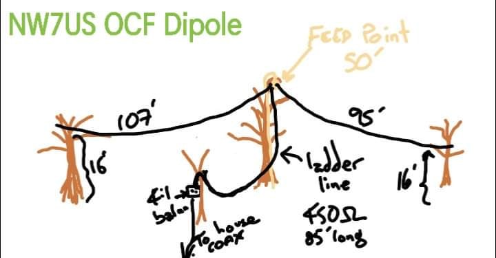 Here is a snapshot of an hour of WSPR at 10w on 40m, using this antenna: 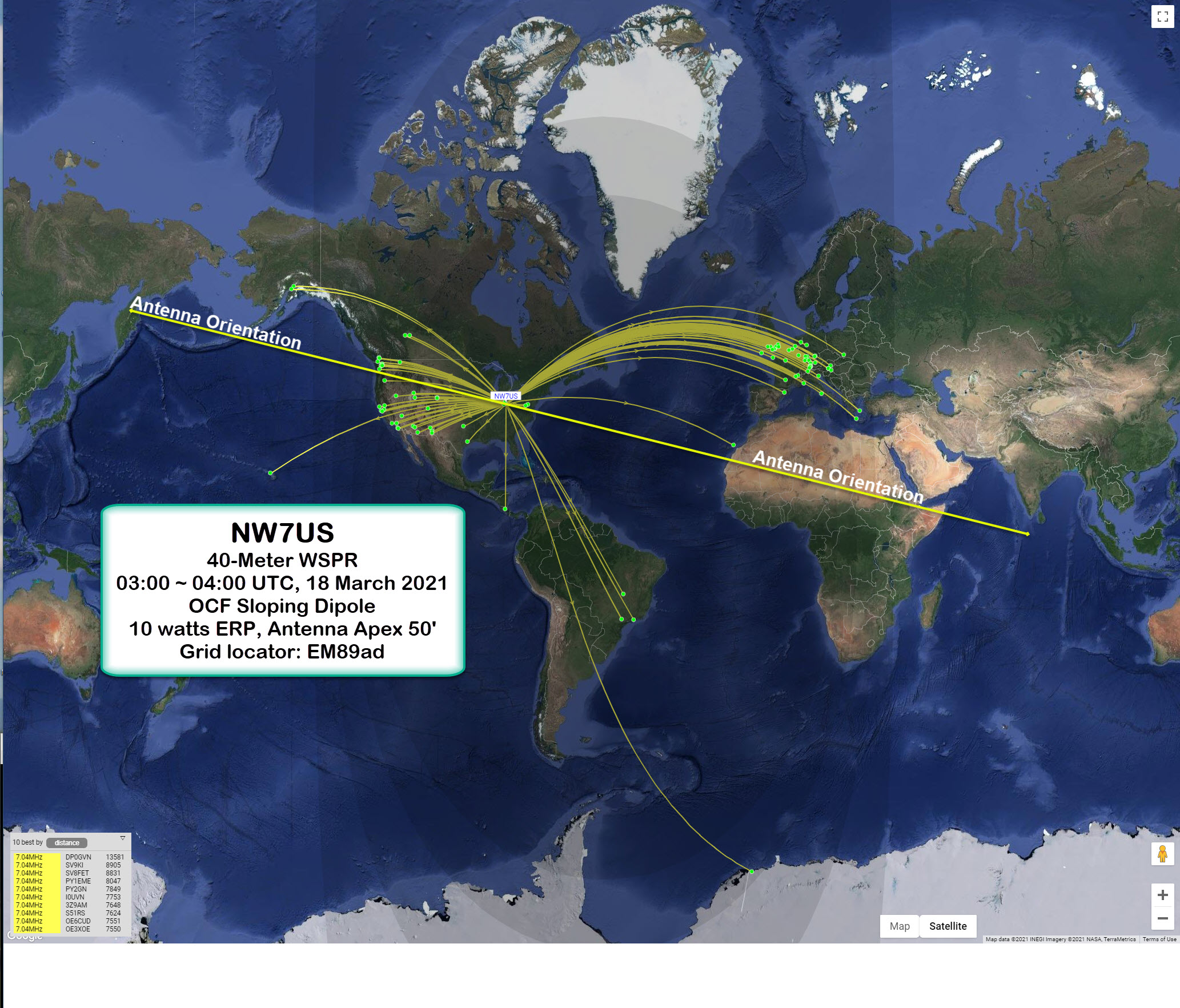 |
|
|
|
[#8]
More Details About My 192' OCF Sloping Dipole
Proof in the pudding: Late in the night, at 07:10 UTC on 18 March 2021, I heard a station in France, talking with different stations on 40 Meters. His station signals were coming in at about 10 dB over s-9. That's pretty strong. I called once (meaning, I spoke my call sign, NW7US, once -- only once), and the French operator immediately answered me. We had a short QSO. It was afterward that I noticed I was only running 50 watts! He gave me a 5-dB-over-s-9 report! I guess the new antenna works very well on 40 Meters. Here's a crude drawing made on my Droid: This is the off-center-fed sloping dipole (or maybe a doublet) antenna erected this past Friday (12 March 2021) with the help of my Son, KF7IBY, Robert. We were able to get the feed point up to the 50-foot point - which is 15.24 meters high. The legs of the antenna drape down to about 16 feet at their ends - or 4.8768 meters high. One leg is about 107 feet in length, while the other is about 95 feet in length -- that is a total of 202 feet or 61.5696 meters total length. The azimuth of the dipole is approximately 284 degrees Westward, and 104 degrees Eastward. The feedline is 450-ohm ladder line that runs from the feedpoint, down about 35 feet, then drapes over to another tree in which is a 4:1 current balun. Total run of 450-ohm ladder line is about 87 feet (actual) or 26.5 meters, give or take a few. The 4:1 current balun is then connected to a 100-foot LMR 50-ohm coax that runs to a grounding and lightning arrestor, and then up into the radio shack (room). The coax terminates into an LDG AT-100ProII auto tuner, which feeds to an Icom IC-7610. This map illustrates the reception of my 10-watt 40-Meter transmissions between 03:00 UTC to 04:00 UTC on UTC date 20-March-2021 (just a little while ago, this evening). The surprise QSO with the station in France, plus this WSPR plotting tells me that the antenna has great potential. 73 de NW7US dit dit . . |
|
|
|
[#9]
I may be wrong about this, but I think an OCF Dipole is considered a balanced antenna.
An unbalanced antenna is any antenna that has part of it connected to a ground system. An OCF dipole is still a dipole and no part of the transmission line is connected to an earth ground. Even EFHW, Loops, quads, mag loops, antennas are considered balanced antennas and antennas because no part is connected to ground. It does get a bit fuzzy, but eve the impedance is the same on both wires at the feed point of an OCF dipole even though the lengths are not the same. The impedance is a function of where on the wavelgth of the wire the connection is. I think even a non-resonant dipole is considered a balanced antenna. I think the only non-balanced antenna is a 1/4 wave vertical which would include a 1/4 wave inverted L. Everything else I can think of I think is considered balanced because no part is connected to ground. (even though the qequipment may or may not be connected to ground, the antenna does not need it to work sort of ) Once the antenna gets at least 1/2 wavelength long, even none resonant, it is by definition a dipole no matter where it is fed. So you end up having a balanced antenna that is not really balanced, just like my 160m doublet because one side is in trees and one side is mostly not, it is considered an unbalance balanced antenna, which means the feedline radiates some because of out of phase currents. Like most labels, there is the pure on both sides, ie perfectly balanced antenna and feedline ie a perfect center fed doublet and perfectly unbalanced feedline coax and a 1/4 wave ground mounter vertical. Then you have all the fuzzy stuff in the middle because labels aren't perfect. But I would think the OCF dipole would be considered an unbalanced ( in execution ) balanced ( dipole ) antenna. But maybe I am wrong. |
|
|
|
[#10]
This post gets the like button.
I am really wanting to build an 80m dipole. My other want to do project is an old timey looking CW practice oscillator that can do Iambic paddles and a straight key. Thinking, wooden box, decent speaker with a vintage looking grill or fabric covering. Yea the innards might have to be modern but I think I would like such a project versus some cheap ugly looking little circuit board kit with a bad speaker and spring tab key. |
|
|
|
[#11]
Is you 160m horizontal loop antenna still in the works? The drawings look sweet. Wish I had the real estate.
|
|
|
|
[#12]
@Mach
If there is current flow on the outside of the coax, as there is on an OCFD, then the by definition the antenna is unbalanced. In the above system, which is impressive BTW. By design, the currents are out of balance in the feed line which causes the feed line to radiate. Notice, the OP has a nice vertical run of feed line, this operates the same as a vertical in that it has a low angle of radiation. Somebody* used to sell an OFCD where the coax had a 1:1 choke balun 20-30 feet down which allowed that section of line to radiate. The idea of the choke balun was to keep RFI out of the shack and allow that vertical section of line to operate as a radiator. hth 73, Rob *ETA: It's the Carolnia Windom |
|
|
|
[#13]
Quoted: @Mach If there is current flow on the outside of the coax, as there is on an OCFD, then the by definition the antenna is unbalanced. In the above system, which is impressive BTW. By design, the currents are out of balance in the feed line which causes the feed line to radiate. Notice, the OP has a nice vertical run of feed line, this operates the same as a vertical in that it has a low angle of radiation. Somebody* used to sell an OFCD where the coax had a 1:1 choke balun 20-30 feet down which allowed that section of line to radiate. The idea of the choke balun was to keep RFI out of the shack and allow that vertical section of line to operate as a radiator. hth 73, Rob *ETA: It's the Carolnia Windom There is current flow on the outside of the coax in a center fed dipole too, but that is because of the impedance mismatch of going from a 50 ohm unbalanced coax to a 74 ohm dipole antenna in free space, but the antenna is still a balanced antenna. This would meet your definition of an unbalanced antenna because of the current flow on the outside of the coax, yet a center fed dipole is considered a balanced antenna. The dipole, without reference to fed point location, is considered a balanced antenna. Even with the OCF Dipole, the impedance mismatch is what causes the common mode current. The 50 ohm coax connected to the 200 ohm ( or what ever the impedance is for where ever along the dipole it is connected ) causes the common mode current. You can also take an 80 meter doublet fed by open line being completely balanced line to a balanced antenna and put a 160 meter signal on the balanced line and balanced antenna and the feedline will radiate just like a Corolina Windom because the antenna part is only 1/4 wave on 160 ( instead of 1/2 wave on 80 ) and you get uneven currents on the feed line. So is that still considered a balanced antenna? The only definition I have read about being unbalanced, either feedline or antenna, is if the shield is connected to ground. However maybe we are just talking semantics. There is balanced antenna and balanced feedline ( doublet ) and there is an unbalanced antenna and unbalanced feedline ( 1/4 wave vertical and coax ) and everything else is somewhere in the middle, but what is considered balanced and unbalance feedline is fairly constant ( open line vs coax ) and then there is the antenna. I think the convention allows for a balanced antenna ( Center Fed Dipole ) that isn't really balanced due to environment ( metal, trees, house ) , because it isn't in free space but people still call it a balanced antenna, it just isn't really balanced. The OCF dipole maybe can go either way, it gets muddy, no part of the antenna is connected to ground, yet the design is by design, not just by implimentaion, not of equal lengths so is inherently not balanced, yet the literature says a dipole is a balanced antenna. Is there an unspoken assumption of the dipole being center fed or is the OCF Dipole the exception to the rule? Either way, I have always wondered what the right answer is, assuming there is a right answer. |
|
|
|
[#14]
Not to my mind, impedance mismatch and unbalance are two different things. Here is K0BG on unbalanced antennas.
I call your attention to the first paragraph of K0BG's discussion on "common mode" current. I cannot accept the notion that impedance mismatch will cause a change the current path unless there is also some other problem with the BALANCE in an antenna system. In a properly functioning dipole the currents on each conductor, antenna and coax, have to be equal. ie. Kirchoff's Laws on current flow. Consider the OCFD, in many cases a tuner is needed due to the impedance mismatch, even when that is corrected with the tuner supplying a conjugate match. (Maximum current flow at all junctions with the antenna system.) There is still the balance problem because of the difference in the length of the elements of the antenna. The balance problem can be corrected with a 1:1 current balun in conjunction with what ever balun ratio that is used to match the impedance of the OCFD. A perfectly cut dipole, in free space, can be unbalanced if you stick a metal shed under one side. You gotta realize, I was raised, amateur radio wise, by guys that hooked me up with Kurt N Sterba and to some extent Walt Maxwell W2DU. (To Low of an SWR can Kill you.)  I am down to the point of quoting sources though. If you can find a copy of Walt Maxwell's "Reflections" Check out the first chapter. I am down to the point of quoting sources though. If you can find a copy of Walt Maxwell's "Reflections" Check out the first chapter.73, Rob |
|
|
|
[#15]
I always thought the impedance needed to match in each leg for an antenna to be considered balanced. If they aren't equal the feedline currents won't be equal and opposite. If the currents in open transmission line aren't equal and opposite they won't cancel out and it will then radiate.
I'm general impedance mismatches cause a reflection and result in current coming back down the feedline. |
|
|
|
[#16]
@Nmbmxer
You're right as far as my understanding goes. With an impedance mismatch, if there is too much impedance the tuner sends up capacitance, too much capacitance and the tuner sends up inductance. In the sense of tuning, capacitance and inductance cancel each other out. How they match the resistance is well beyond me. For Impedance |Z| = R2 + (XL2 - XC2) Note how XL and XC cancel each other due to the minus sign between them. XL and XC are inductive and capacitive reactance respectively. It's getting harder to put the formulas down with a proper source of the character. 73, Rob ? |
|
|
|
[#17]
@Mach
Hi Mach I finally found a reference, it's in the form of a photo of some text from Walt Maxwell's "Reflections III" Copyright 2010 by CQ Communications. Chapter 2 page 4 note 20. Note that the radiation from current on the outside of the coax (feed Line) is a result of asymmetrical positioning with respect to the antenna. This why people go on about how the feed line should come away from the antenna at 90 deg. Further down it states that this condition has no relationship to the level of SWR on the line. I had to work for it. LOL Thanks for the push. 73, Rob |
|
|
|
[#18]
Quoted: @Nmbmxer You're right as far as my understanding goes. With an impedance mismatch, if there is too much impedance the tuner sends up capacitance, too much capacitance and the tuner sends up inductance. In the sense of tuning, capacitance and inductance cancel each other out. How they match the resistance is well beyond me. For Impedance |Z| = R2 + (XL2 - XC2) Note how XL and XC cancel each other due to the minus sign between them. XL and XC are inductive and capacitive reactance respectively. It's getting harder to put the formulas down with a proper source of the character. 73, Rob ? My understanding is that the only thing that is matched is the line between the transmitter and the tuner. The tuner does nothing to the feedline to the antenna and the antenna. The tuner doesn't send anything up to the antenna. It all happens between the transmitter and the tuner to prevent the finals from getting destroyed. The feedline and the antenna will still have a high SWR. All of that current going up and down the feedline ( it keeps bouncing between the tuner and the ends of the antenna from the SWR ) will either turn into heat or radiate. In a coax it is mostly heat due to the shield and the dielectric. In open line it is mostly radiated because there is no shield or dielectric which is why even high SWR antennas will be very efficient when fed with open line. The Resistance mismatch is never matched. If the antenna is 74 ohms and the coax is 50, there will always be that mismatch, the tuner does nothing in that regard. The only capacitance and inductance that gets cancelled out is between the transmitter and the tuner. |
|
|
|
[#19]
Quoted: @Mach Hi Mach I finally found a reference, it's in the form of a photo of some text from Walt Maxwell's "Reflections III" Copyright 2010 by CQ Communications. Chapter 2 page 4 note 20. Note that the radiation from current on the outside of the coax (feed Line) is a result of asymmetrical positioning with respect to the antenna. This why people go on about how the feed line should come away from the antenna at 90 deg. Further down it states that this condition has no relationship to the level of SWR on the line. I had to work for it. LOL Thanks for the push. 73, Rob https://www.ar15.com/media/mediaFiles/222502/Text_from_Reflections_Chap_2_pg_4__jpg-1872201.JPG I agree. 1. The imbalance in the antenna results is common mode current, either on the outside of the coax, but also inside the coax but we don't care about the inside because it is shielded, and also on both lines of the open line and how far out of phase they are will determine how much they radiate ( because they don't cancel completely ) being out of phase. 2. Also there is a reflection due to an impedance mismatch at the feedline and antenna junction that causes a current back down to the tuner / transmitter. 3. Then there is also a reflection of power and SWR due to the length of the antenna relative to the operating frequency. There are 3 sets of waves of varying magnitude going up and down the feedline and antenna based on those 3 things above. All result in either heat and loss, or the signal being radiated either from the feedline for a not perfectly balanced antenna or feedline or the antenna from a mismatch between the freq and the wavelength of the antenna ( High SWR because the antenna is too short or too long ). All three of those currents are in constant partial reflection and constant continuing through the junction at each junction. The tuner connection, the feedline / antenna junction, and the end of the antenna with space. |
|
|
|
[#20]
I have been enjoying the discussion you've been having in response to my original post.
I have gained quite a number of new Countries/Entities for my DXCC, with this antenna. More on that in a later post. I have LEARNED more about the feedline/antenna system and what you've been discussing, so I thank each of you that took the time and energy to talk about these engineering/academic aspects of the antenna systems. I'm digging into this topic, now, because you have made me hungry for more information -- this is right up my alley. I knew that my open line feed line was part of the radiating portion of this antenna system. That is why I tried to keep it as vertical as possible, but I could not succeed (yet). The results in the real world are impressive, to me. This is one of the best wire antennas I've ever made and used. 73 for now. |
|
|
|
[#21]
@Mach
Try an experiment, you'll need a small 50 Ohm load, your tuner, antenna analyzer, and open wire fed dipole. Tune up on your dipole using the outboard tuner, say on 20M. Open the connection between the tuner and antenna and "look into the antenna system" with the analyzer. You may need a 1:1 balun here. Record the readings in R +/- J at the frequency used to tune the antenna. The important things are the "R" value, the "J" value and the sign of the "J" factor. Now, disconnect the radio from the tuner and put the 50 Ohm dummy load on the input (where the rig connects) of the tuner. The 50 Ohm load will represent the radio. Look back into the tuner output (antenna side) towards the receiver with the analyzer, with out changing anything of the adjustments on the tuner or analyzer, record the "R" +/- "J" values as seen by the analyzer looking through the tuner to the 50 Ohm load on the input. Let us know what you get. 73, Rob ETA: This may work better with a coax fed antenna or where the balun is outboard from the tuner. Make the break between the tuner and balun to take your measurements. |
|
|
|
[#22]
Quoted: @Mach Try an experiment, you'll need a small 50 Ohm load, your tuner, antenna analyzer, and open wire fed dipole. Tune up on your dipole using the outboard tuner, say on 20M. Open the connection between the tuner and antenna and "look into the antenna system" with the analyzer. You may need a 1:1 balun here. Record the readings in R +/- J at the frequency used to tune the antenna. The important things are the "R" value, the "J" value and the sign of the "J" factor. Now, disconnect the radio from the tuner and put the 50 Ohm dummy load on the input (where the rig connects) of the tuner. The 50 Ohm load will represent the radio. Look back into the tuner output (antenna side) towards the receiver with the analyzer, with out changing anything of the adjustments on the tuner or analyzer, record the "R" +/- "J" values as seen by the analyzer looking through the tuner to the 50 Ohm load on the input. Let us know what you get. 73, Rob ETA: This may work better with a coax fed antenna or where the balun is outboard from the tuner. Make the break between the tuner and balun to take your measurements. @robmkivseries70 That is going to take a bunch of disconnections. Right now I can't do that because I just had surgery and can't be bending my head over, so it will have to wait a few weeks. I also do not have a 1:1 balun. But I also have a coax fed antenna I can use which will make it easier and not need the 1:1 balun. Until I can actually do it, my guess is that I will get the exact opposite complex reading of what I got looking at the naked antenna. If the antenna is capacitive, then the tuner will add inductance to resonate the antenna and vice versa. the + or - J is just the measurement of overall inductance or capacitance. If the antenna is giving me a -200J then the tuner at resonance will add +200J. The R isn't going to change. It may actually change a little because the inductor does have a small amount of Resistance that it will be adding to the resonant circuit, but it should not be significant and that amount of R that the inductor adds will turn some power into heat which is what is responsible for the loss in he tuner.. assuming I can adjust the tuner to a perfect resonance, if I get a +XJ looking at the naked antenna, then I will get a -XJ looking back at the dummy load in place of the radio from were the antenna connects to the tuner. I don't think it matters which direction you look at an LC circuit ( tuner ) , it will show the same. All the tuner does is resonate the antenna ( to include the coax to the antenna ) to zero complex impedance. It doesn't change the R value, just the capacitive / inductive value to zero out the complex part ( capacitance / inductance ). That is the definition of resonance a +-0 complex impedance, actually that is just the result, the definition is actually zero phase shift between the current and the voltage so that the current and voltage are in phase which is essentially saying that the complex part of the impedance is zero ( no + and no -) Lets take a short vertical. We add a base loaded inductor to tune the vertical to freq. That is no difference than using a tuner in the shack to tune the short vertical. The tuner will need to add about the same amount of inductance that the base coil added. The difference will be the loss in the coax due to the coax between the tuner and the short vertical becoming part of the resonant circuit and will create loss. The base loaded vertical will have less loss because the coax to the coil will not be part of the resonant circuit. The coil just zeroes out the capacitance of a short vertical using inductance, just like a tuner if you disregard the impedance of the coax. That is why people use a base antenna autotuner. With a tuner, when a non-rolling inductor is used, and fixed inductor values are manually or automatically selected, if the best match has extra inductance then a capacitor cancels that extra inductance out. The input capacitance is added to match the extra inductance looking at the antenna. Now looking back at the radio, we just added inductance, so to match the impedance output of the radio we have to add capacitance to cancel out the inductance looking the other way to the radio. So actually I may be wrong about it doesn't matter which way you look into the circuit either from the radio or from the antenna side of the tuner. But I think it should be the same since once you set the capacitance and inductance it should not matter which way you look at it, but I may be wrong about that, the 'load' at either end might make a difference in the readings. Disconnect everything from the tuner and no matter which way you look at it the value will be the same without a load. Adding load like the dummy load for the radio may change the reading, I don't know. I will have to think about that some more. That is the way I understand it. I will do the experiment when I can, but it will be a while. |
|
|
|
[#23]
@Mach
Hi Mach, no worries. Sorry to hear you had surgery. I believe you are right, you should get the same numerical reading with the sign reversed on the "J" factor. Take it easy. 73, Rob |
|
|
|
[#24]
Quoted: @Mach Hi Mach, no worries. Sorry to hear you had surgery. I believe you are right, you should get the same numerical reading with the sign reversed on the "J" factor. Take it easy. 73, Rob Just brain surgery, apparently I had some extra that needed to come out, wasn't fair to everybody else that I had some extra
|
|
|
 Win a FREE Membership!
Sign up for the ARFCOM weekly newsletter and be entered to win a free ARFCOM membership. One new winner* is announced every week!
You will receive an email every Friday morning featuring the latest chatter from the hottest topics, breaking news surrounding legislation, as well as exclusive deals only available to ARFCOM email subscribers.

AR15.COM is the world's largest firearm community and is a gathering place for firearm enthusiasts of all types.
From hunters and military members, to competition shooters and general firearm enthusiasts, we welcome anyone who values and respects the way of the firearm.

Subscribe to our monthly Newsletter to receive firearm news, product discounts from your favorite Industry Partners, and more.
Copyright © 1996-2024 AR15.COM LLC. All Rights Reserved.
Any use of this content without express written consent is prohibited.
AR15.Com reserves the right to overwrite or replace any affiliate, commercial, or monetizable links, posted by users, with our own.