|
[#1]
Interesting concept. Let us know how it goes.
|
|
|
|
[#2]
I've got one installed pretty much as you describe except I built a tilt mount for mine. There's a better set of instructions in the GAP Antennas groups.io
|
|
|
|
[#3]
Quoted:Interesting concept. Let us know how it goes. Quoted:Interesting concept. Let us know how it goes. Quoted:I've got one installed pretty much as you describe except I built a tilt mount for mine. There's a better set of instructions in the GAP Antennas groups.io |
|
|
|
[#4]
For what it's worth, I've had a Gap Challenger DX since about 2004. That manual suggest 3 guys, and I did that at first.
Wind took it down in 2010. Gap told me on the phone they recommend 4 guys now. I reinstalled it a couple of years ago, with 4 guys, and it's been fine. So even though the Titan manual suggests guys, it would be a good move to install them to be on the safe side. Just a thought. Good luck with your new antenna! |
|
|
|
[#5]
Quoted: For what it's worth, I've had a Gap Challenger DX since about 2004. That manual suggest 3 guys, and I did that at first. Wind took it down in 2010. Gap told me on the phone they recommend 4 guys now. I reinstalled it a couple of years ago, with 4 guys, and it's been fine. So even though the Titan manual suggests guys, it would be a good move to install them to be on the safe side. Just a thought. Good luck with your new antenna! |
|
|
|
[#6]
OK, work was kind of quiet today, so I took off early and started the install.
I've decided to put it up against the far end of one on my sheds. Should be a solid setup, plus it's near the few trees we have around and will be less obtrusive. I bought a 10' piece of 1-1/4" galvanized pipe to use as a mast. Here is a view of the shed from the house side. The top of the mast & mounting plate is visible at the left end of the roof and the vertical wire is the to the feed point of my existing OCFD, which will be coming down.  I had a 4" 'standoff kit' from Antenna Master and used that to mount the mast. Because the shed roof gable overhand exceeds 4", I made a block to space the mount out enough to clear the edge of the shingles. I used 1/4" x 3-1/2" lag screws and made sure to hit the internal 2x4 framing. Here is the mast now in place:  The mast is plumb in both directions and very solid. Now all I need to do is assemble the antenna. I ran out of time (and steam) tonight. They're calling for rain tomorrow and it's our ARC meeting tomorrow night anyway, then my mom's birthday party is Saturday, so I probably won't get a chance to get the antenna assembled and put up until Sunday. I did get the parts sorted out and inventoried, and have a couple saw-horses to use for assembly, so I'm ready to move forward as soon as I can get some free time. More to come... |
|
|
|
[#7]
Hard to to tell from the pic but the bracket has to be insulated from the pipe and I seem to recall someone saying that it was important that the bracket be flush with the top of the pipe. You're going to need some help standing it up. I built a tilt mount for mine from a piece of aluminum box tubing that I had on hand.
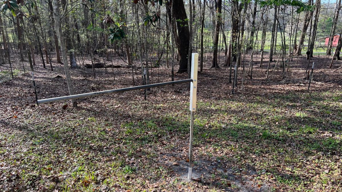 Note the color of the arrows. 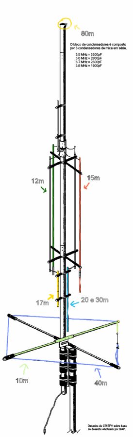 Some tuning notes I've gleaned from the web. I haven't bothered tuning mine other than the 40M counterpoise. I need to tune 15M GAP TITAN TUNING Summary: The GAP Titan is resonant at ALL bands now allthough 30m is a little bit low. 20m bandwith is not so broad as it seemed to be first, but it is a multyresonance Problem. All this mods lowered my 30m resonance to 9.990. But because at 10.100 the SWR is less then 1.4, this is not a real problem. Only by means of interest I will try to add some cm of wire to the lower element of the GAP tomorrow morning. 10m: that was a little bit tricky. Adding some wire to the wire extention at the rod with the yellow cap had NO result. I added a piece of wire to the NON isolated aluminia tube oposite to the tube, where the short wire extention is connected )That one, with the yellow cap). My wire is abt 1 Meter long. This brought the 10 m resonance down to 28.100, the 40m resonance now was to low. I shortened the long counterpoise wire by 20cm. Now 40 m is resonant at 7.070 and 10m is resonant at 28.120 Here are the results: 15m: no problem, adjusted the rod with the long ectention. Now resonant at 21.060 12m: no problem, adjusted the rod with the short extention. Now resonant at 24.980 17m: no problem, adjusted the shorter of the lower rods with an additional alu tube, resonant at 18.090 20m: The extraordinaire bandwith is a sum of resonant QRGs. I added a piece of alu tubing at the longer lower rod. 20 m resonant now at 14.070 For 80M: I suspect they are silver mica capacitors. Color Value Freq. -------------------------------------------------- Black 3300pf 3.5MHz White 2800pf 3.6MHz Red 2300pf 3.7MHz Blue 1900pf 3.8MHz Green 1500pf 3.9MHz Clear/Orange 1400pf 4.0MHz The slotted extender by itself controls 12m. The slotted extension with the 23" extension below it controls 15m. |
|
|
|
[#8]
Quoted: Hard to to tell from the pic but the bracket has to be insulated from the pipe and I seem to recall someone saying that it was important that the bracket be flush with the top of the pipe. You're going to need some help standing it up. I built a tilt mount for mine from a piece of aluminum box tubing that I had on hand. https://www.ar15.com/media/mediaFiles/22957/tempImagexk4Cjb-2845208.jpg Note the color of the arrows. https://www.ar15.com/media/mediaFiles/22957/Titan_pt-2845225.gif Some tuning notes I've gleaned from the web. I haven't bothered tuning mine other than the 40M counterpoise. I need to tune 15M GAP TITAN TUNING Summary: The GAP Titan is resonant at ALL bands now allthough 30m is a little bit low. 20m bandwith is not so broad as it seemed to be first, but it is a multyresonance Problem. All this mods lowered my 30m resonance to 9.990. But because at 10.100 the SWR is less then 1.4, this is not a real problem. Only by means of interest I will try to add some cm of wire to the lower element of the GAP tomorrow morning. 10m: that was a little bit tricky. Adding some wire to the wire extention at the rod with the yellow cap had NO result. I added a piece of wire to the NON isolated aluminia tube oposite to the tube, where the short wire extention is connected )That one, with the yellow cap). My wire is abt 1 Meter long. This brought the 10 m resonance down to 28.100, the 40m resonance now was to low. I shortened the long counterpoise wire by 20cm. Now 40 m is resonant at 7.070 and 10m is resonant at 28.120 Here are the results: 15m: no problem, adjusted the rod with the long ectention. Now resonant at 21.060 12m: no problem, adjusted the rod with the short extention. Now resonant at 24.980 17m: no problem, adjusted the shorter of the lower rods with an additional alu tube, resonant at 18.090 20m: The extraordinaire bandwith is a sum of resonant QRGs. I added a piece of alu tubing at the longer lower rod. 20 m resonant now at 14.070 For 80M: I suspect they are silver mica capacitors. Color Value Freq. -------------------------------------------------- Black 3300pf 3.5MHz White 2800pf 3.6MHz Red 2300pf 3.7MHz Blue 1900pf 3.8MHz Green 1500pf 3.9MHz Clear/Orange 1400pf 4.0MHz The slotted extender by itself controls 12m. The slotted extension with the 23" extension below it controls 15m. |
|
|
|
[#9]
The forecasted rain held off and I again bailed out early from work to work on this project...This OCD thing is ugly...
Anyway, I got the antenna assembled today. The main vertical assembly is sitting on sawhorses, ready to go up.  It actually went together very easily and smoothly, and there was only one minor glitch: The "middle section" would not slide into the "main section" far enough to align the screw holes, so I trimmed off the 1/8" required to get alignment. Otherwise just followed the directions. I loosely assembled the "counterpoise assembly" and have that laying flat in the driveway for the moment:  I'm going to clamp that on once I get the antenna mounted on the temporary mast for testing. Once it checks out, I'll take it back off to allow us to maneuver the main assembly into place on top of the permanent mast, then reinstall it. Speaking of "permanent mast", I need to replace the 1-1/4" pipe mast I have with a 1" pipe. I bought the wrong pipe, based on incorrect terminology in the antenna manual. The manual said to use 1-1/4" pipe, which I bought and installed, but they really mean 1-1/4" OD, which I found out when I unpacked the parts and found the insulators and U-Bolts - the insulators won't go over the pipe, and if i made my own, the U-Bolts wouldn't fit. Pipe is sized by ID, so I really need a 1" pipe, which will come close to the 1-1/4" outside diameter actually needed. I've got some small Dacron rope I need to cut into lengths for guys, so replacing the pipe and setting up the guys are on tomorrow morning's agenda. If I can get my buddy over here in the morning, we'll get the antenna up before I head over to my mom's for her birthday party. If not, we'll put it up Sunday. |
|
|
|
[#10]
I used 1" Galv water pipe for mine which I think is what they called for. Instructions leave a lot to be desired.
|
|
|
|
[#11]
That ought to "kick ass and take names", the elevation will yield a bit lower take off angle and get the signal up above the ground clutter.
73, Rob |
|
|
|
[#12]
Quoted:I used 1" Galv water pipe for mine which I think is what they called for. Instructions leave a lot to be desired. Quoted:I used 1" Galv water pipe for mine which I think is what they called for. Instructions leave a lot to be desired. Quoted:That ought to "kick ass and take names", the elevation will yield a bit lower take off angle and get the signal up above the ground clutter. 73, Rob As noted above, I replaced the mast pipe and that's ready to go. A friend came over yesterday morning and we stood the Titan DX up in the driveway, using the MFJ Tripod that came with it in the package deal. VERY awkward to handle. I had a scrap of 1-1/4" PVC about 5 feet long, so we used that as a temporary mast in the tripod. The tripod isn't too bad for 'MightyFineJunk', but I did have to drill out one screw hole to let one of the handscrews go through the bracket. Once up, it was pretty stable, and I have 4 temporary guys on it.  I just had time before heading to mom's to do a quick check with my antenna analyzer and I was very pleasantly surprised to see the resonance is very close and, except 75/80 meters, is probably "good enough" as is. Here's what I got during preliminary testing: 75/80m: SWR was highest at 3.6 mHz and lowest at 3.9 mHz. The high reading was 3.0:1, the low reading was 2.8:1. 40m: SWR was a flat 2.1 across the band. 30m: 10.100 mHz: 1.8:1 10.125 mHz: 1.7:1 10.150 mHz: 1.8:1 20m: 14.000 mHz: 1.7:1 14.175 mHz: 1.5:1 14.350 mHz: 1.3:1 17m: 18.068 mHz: 1.0:1 18.118 mHz: 1.0:1 18.168 mHz: 1.2:1 15m: 21.000 mHz: 3.1:1 21.225 mHz: 1.4:1 21.450 mHz: 2.2:1 12m: 24.890 mHz: 1.3:1 24.990 mHz: 1.7:1 10m: 28.0 mHz: 2.0:1 28.5 mHz: 1.6:1 29.0 mHz: 1.6:1 I didn't do anything to change tuning yet, figuring that this initial test was just to identify any potential issues before mounting it up higher. Once it's in place, I will run through the tests again and try to tweak it a little. I'll be able to stand on the shed roof and reach anything I could change, (edit:) The bottom counterpoise crossbars sag some and I will probably put some guy lines from the tips of the crossbars up to the main antenna. HT again to 'CS223' for the tuning diagram and info!! My buddy (glutton for punishment) is heading back over here in a little while and we're going to finish the install today with any luck. Going to get thunderstorms here tomorrow, so we'll have a 'trial by fire' right away! I'll post more pics and test results when we get it going. |
|
|
|
[#13]
Excellent!
|
|
|
|
[#14]
Quoted:Excellent! Finished the installation today. Still have to test it in it's new position and connect it to the house cable, but I was pretty much done in by the time we finished getting it hung and it was time to eat anyway... This 'getting old' shit ain't for sissies. Hopefully get it checked out Tuesday afternoon, tomorrow's schedule is already full. I have the bottom of the 10' mast up about 6", so the base of the antenna is about 9'6" off the ground. We found it best to connect the antenna to the tripod first, and then later to the mast before raising it. The antenna is just too awkward to handle with 20' extended above the highest point one can reach/try to control the antenna from. The first attempt was each of us standing on 6' step ladders trying to get the antenna onto the adapter plate on the temporary mast in the tripod (only 5 feet off the ground), which was quite an unsuccessful struggle for a couple old men. We then laid the tripod over and attached the antenna the the short 'test mast', then raised it as an assembly. We did the same thing when we attached it to the 10' x 1" permanent mast and it was much easier to control than our first attempt. I will say I thought sure we would end up with the main mast of the antenna buckling and kinking when we were raising it due to the cantilevered weight. It is very difficult to support the long antenna hanging out behind you as you walk it up, so all of the stress/weight is right where your hands are pushing it up. We used a 6' squeegee as a prop to help push upward, but there are still certain times the antenna is unsupported and at risk of buckling and it held up fine. To set up the guy lines, I used a hose clamp around the center section, with cable ties doubled around the hose clamp at 0o, 90o, 180o and 270o, then looped some 1/8" Dacron line through the cable ties. The guy lines were a little difficult to sort out once the antenna was raised, and we had been pretty careful to lay them out the way we thought they should go. I eventually had to go get binoculars to see which line should be in what position. The bottom line is that when you raise the antenna, the guys all clump together and have to be flipped up over the ends of the tuning rods to index correctly. We spent an inordinate amount of time dicking around with the guy lines, but once we had everything straight, it was easy to guy solidly. It may have been easier if we had 3rd/4th persons to keep the guys sorted as the two of us raised the antenna into position. After finishing the Titan DX install, I couldn't get my OCFD out of the tree - the suspension line (1/4" Dacron) seems to have grown into a crotch and it wouldn't pull in either direction. I fooled with that for an hour and had to give up for now. The rope passes over a 4" horizontal limb, then through a crotch in a 4" horizontal limb 4 feet away, which is about 40 feet AGL, so there's no way to safely reach it. Might have to get the truck involved...or a rifle. I had hoped to re-purpose the coax for the new vertical, not to mention recovering a relatively expensive store-bought antenna and a bunch of Dacron rope. Supposed to rain here tomorrow, I'll try pull it it down again while it's wet... Here's the Titan DX's current position:  I'll post test results when I get a chance to wrap this up. ETA: 1) Got my OCFD down, finally. It had grown into the tree crotch pretty solidly and I actually DID have to get the truck involved (as an anchor for the come-along). I braided together the wires that were hanging from the balun (coax and the two heavy wires that form the dipole legs) to distribute the pulling pressure and wrapped that around an empty wire spool to avoid kinking. I then hooked a come-along to my truck hitch, put a heavy rope through the core of the spool to hook the come-along to and cranked down on the come-along. Put a LOT of tension on it and ran out of come-along cable. I pulled down on the tensioned wires using almost all of my body weight and the rope finally popped loose and slid through the crotch. Resistance to pulling the rest of the rope through was pretty substantial, but I did get everything down without damaging anything. I was surprised and really thought I'd tear the connector off the coax. The suspension rope was 1/4" Dacron and the part that had bonded to the tree literally tore loose and there was a notch in the rope about 10% of the way through. 2) Once I got the OCFD down and tested the coax good, I hooked everything up, but then had problems when testing from back inside the shack. Open circuit indication. Fooled with it awhile and found that one of my older MFJ coax switches has developed a problem with one of the contacts and it was an open circuit. Swapped a barrel connector for the switch and was in business. I'll open the switch housing up later and see what's wrong...knowing MFJ, something probably fell apart inside. 3) Compared to the test run on the tripod on the driveway, SWR had improved on all bands once erected in it's final position. My highest SWR on any band was 2.7:1 (80m) and in many spots I had between 1:1 and 1.5:1. I was using my RSPDuo SDR to look at signals, so I didn't transmit. The bad coax switch was used to select between the SDR and my TS590s and I didn't have time to swap cables on the barrel connector last night. I have another switch and will put that in line and probably try to TX some tonight. It did seem like these was an increase in background noise over the OCFD, which I had expected. Everything else seemed to come through better too, so it's probably all good. Got hooked up and working just in time to hear a Panama station and a northern Spain station coming through at 59. |
|
|
 Win a FREE Membership!
Sign up for the ARFCOM weekly newsletter and be entered to win a free ARFCOM membership. One new winner* is announced every week!
You will receive an email every Friday morning featuring the latest chatter from the hottest topics, breaking news surrounding legislation, as well as exclusive deals only available to ARFCOM email subscribers.

AR15.COM is the world's largest firearm community and is a gathering place for firearm enthusiasts of all types.
From hunters and military members, to competition shooters and general firearm enthusiasts, we welcome anyone who values and respects the way of the firearm.

Subscribe to our monthly Newsletter to receive firearm news, product discounts from your favorite Industry Partners, and more.
Copyright © 1996-2024 AR15.COM LLC. All Rights Reserved.
Any use of this content without express written consent is prohibited.
AR15.Com reserves the right to overwrite or replace any affiliate, commercial, or monetizable links, posted by users, with our own.