|
[#1]
Quoted: Inherited a BlueSky crank-up mast. I'm in Flower Mound, TX, on a 1/3 of an acre, with a few trees to block it MOSTLY from view from the Karens in the HOA. I anticipate I'd crank it up to full height for a week or so, and bring it down when the weather was getting threatening. I DO have a Comet CHA-250h. Not my favorite, but I couldn't pass it up for the price. @Badger545 mentioned the CP5H is a good antenna off of his roof. I would be able to get a little higher than my roof. What resonant (Not marketing gimmick) antennas are out there that would work well with a 7100 or a 7200 at 100 watts at that height? I'm not a contester; If I make a REAL contact per night, and get to shoot the breeze about anything other than "Antennas, radio, weather, or my health," I'm happy. EDIT: just found the following thread..... https://www.ar15.com/forums/Outdoors/Vertical-HF-Antennas/22-699612/ |
|
|
|
[#2]
A vertical HF antenna on a 33 foot mast is going to need some radials or counterpoise to work correctly. Especially if you're not a big DXer, I'd suggest some kind of dipole in an inverted-V with the center insulator at the top of the mast. I'm somewhat a fan (no pun intended) of "fan" multiband dipoles, which can be homebrewed or there are commercially made versions. They can be made either with the multiple elements in-line and close together, or spaced at angles far apart.
|
|
|
|
[#3]
I have a blue sky at home. It's a pretty decent mast. I keep it in my camping trailer now. Which mast do you have? The AL2 I think is the model with the 4" pipe. The AL1 is smaller 2" or so.
I've far exceeded the limits on both systems. The AL2 has held 150lbs with a 6sqft wind load 40' up for years. I use to have a discone and couple cell yagis on mine. Always wanted to do a 2m ssb big wheel but am saving that for this new tower. |
|
|
|
[#4]
Inverted Vee, Alpha Delta DX-CC fan/trap antenna will give you 80, 40, 20, 15, and 10 meters if you want to buy a ready made one. The downside is that it will have a narrow bandwidth on 75 Meters because of the self-resonant loading coils. Manufacturer's web page on DX-CC
You could also make a fan dipole. Here's how |
|
|
|
[#5]
Quoted: You could also make a fan dipole. Here's how I'm giving serious thought to building this as my first antenna. One question, as the photo in the link doesn't have the detail: How do you attach the tension rope to the top wire? The ends of the other wires have insulators that the tension rope feeds through. Also, the article says 12-gauge wire for top one and 14-gauge for other two. Can I just use 12 for all? Can a person really use the newer method mentioned and not have to do any trimming/tuning? |
|
|
|
[#6]
Hex beam. Theres a few solid options out there for cash and DIY plans.
|
|
|
|
[#7]
Quoted: I'm giving serious thought to building this as my first antenna. One question, as the photo in the link doesn't have the detail: How do you attach the tension rope to the top wire? The ends of the other wires have insulators that the tension rope feeds through. Also, the article says 12-gauge wire for top one and 14-gauge for other two. Can I just use 12 for all? Can a person really use the newer method mentioned and not have to do any trimming/tuning? You'll want to use a 1:1 current balun. they have an eyelet at the top for a rope. 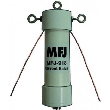 If you're supporting the antenna at the center insulator/balun, 14 gauge wire will be adequate. The weight of most of the antenna is supported by the rope, so the ends have much less tension on them. Read the linked article carefully because it goes into detail about how to trim the antenna elements to length. On my 3 element dipole, I tied all ther elements to the eyebolts on the balun and about 3' out, I put a spacer made from 1/2" PVC pipe to space the elements about 9" apart. You can skip the 15 Meter elements if you want to because the 40 Meter elements will act as 3/2 wave radiators on 15. Matching can be improved on the upper part of the band by using capacity hats like this. Sinche you'll be doing some trial and error adjusting, a handful of split bolt connectors will make it much easier since you won't be constantly wrapping and unwrapping wire. After the antenna is tuned to your satisfaction, the split bolts can be removed and the wires soldered in place. Keep them around as they'll be handy for your next antenna project. Your local electical supply holuse should have them in stock. 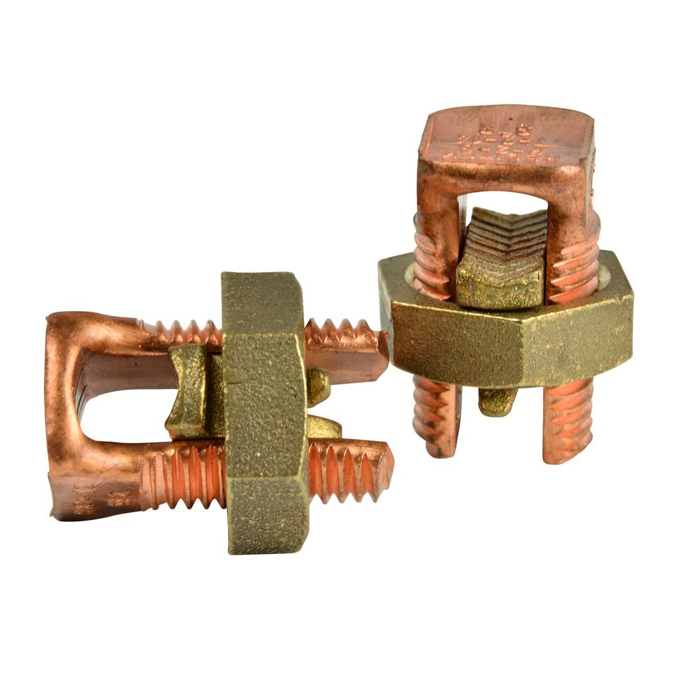
|
|
|
|
[#8]
Quoted: You'll want to use a 1:1 current balun. they have an eyelet at the top for a rope Quoted: You'll want to use a 1:1 current balun. they have an eyelet at the top for a rope  The image above from your link shows the tension rope connecting to the top wire, hence my curiosity. Read the linked article carefully because it goes into detail about how to trim the antenna elements to length. On my 3 element dipole, I tied all ther elements to the eyebolts on the balun and about 3' out, I put a spacer made from 1/2" PVC pipe to space the elements about 9" apart. So I can connect all three wires to the same eyebolt? The new method described in the article says to space the three connection points at least 5.5" from each other. Since you'll be doing some trial and error adjusting, a handful of split bolt connectors will make it much easier since you won't be constantly wrapping and unwrapping wire. I guess it's safe to say that you prefer the pruning method over the newer "no-cutting" method mentioned at the beginning of the article.  |
|
|
|
[#9]
That diagram is a generic layout. There are many options on how to secure the elements avaliable on the Internet. Peruse them and see which one(s) appeal to your construction skills.
Since you'll be supporting the antenna at the center in an inverted vee configuration, you won't have to worry as much about mechanical strength. Wind and ice loading will be the main considerations I tied my elements together at the center and then supported the lower elements from the ones directly above them. I'd take a picture but you can't see anything but the center balun, traps, and end insulators from the ground. The wire is bare stranded copper and once it developed a patina, it disappeared into the sky and trees. You're going to be looking for sources for wire, coax, and components. Here's a few: https://www.coaxman.com/ https://www.dxengineering.com/ https://mfjenterprises.com/ https://www.qsradio.com/index.html Since mechanical stress is not a big concern, you can use #14 stranded house wiring (THHN) for the elements. I prefer 7-strand #14 non-insulated solid copper wire. The steel core (Copperweld) is stronger but a PITA to handle, kinda like the detent spring in an AR-15, but bigger. It looks like the coax run is going to be fairly short so losses won't be too bad for reasonable SWRs. RG-213, RG-8 or RG-8X or their LMR equivalents will be GTG. 3/16" braided Dacron rope will hold it up for years (or until a squirrel chews through it). If you're going to put a pully on the mast to raise and lower the antenna, get a marine-rated one. Make sure the gap between the sheave and the frame is small enough so the rope won't jam in it. |
|
|
|
[#10]
Thanks for the detailed response! I don't want to take over the OP's thread, but I feel that the info might be pertinent to him as well. Plus, it keeps me from cluttering the forum with new threads.
I ordered a 500-foot spool of 3/16" black dacron line this morning before reading the last response, so I'm good to go there. Do I gain any benefits by running the wires horizontally instead of in an inverted-V? If inverted, what angle do I want them at the feed point? I assume the higher I can get the center off the ground, the better? |
|
|
|
[#11]
Horizontal is better, but not by that much. If you have the supports, go for it.
The angle between the two elements of an inverted vee should be somewhere around 120*, 90* as a minimum. ETA: In theory, the gain of an inverted vee is similar to that of a dipole at the same elevation because most of the radiation is from the high-current portion of the antenna, which is near the center. Since the center of both antennas are the same height, there is little difference in performance. Antenna modeling software bears this out for free-space models, predicting maximum gain of 2.15 dBi for the dipole and 1.9 dBi for the inverted vee. However, in practice, ground proximity and ground conductivity as well as end effects reduce the efficiency of the inverted vee considerably compared to the dipole: In the 40-foot example above, considering a useful take-off angle of 40 degrees above the horizon, the inverted vee produces a maximum gain of 1 dBi in a circular pattern, whereas the dipole produces an oval pattern ranging from 6 dBi toward the sides down to 1.2 dBi toward the ends. Elevating the antennas higher above ground somewhat resolves the disparity, but considering the practical, legal and financial limits which influence most antenna installations, the inverted vee will be observably inferior in performance to a dipole by 2 to 4 dB.[1] However, if space is limited, an inverted vee may permit operation on frequencies that would not be possible with a full-sized dipole. SOURCE Something to remember, though is that increasing/decreasing power by 4 times (~6 dB) only increases/decreases an S-meter reading by one S-unit. |
|
|
|
[#12]
OP, something to look at for the top of that mast is either a non-rotateable MFJ-1836 Cobweb, or a rotatable MFJ-1846 Hex Beam. Both cover 20-6 Meters.
The inverted vee would then be used only for 80 and 40 Meters. |
|
|
|
[#13]
I'm going to stick the Comet CHA-250 at the top of the tower for now. Yeah, it's a compromise antenna. I'll whip up an inverted V in the next week or so.
|
|
|
|
[#14]
Quoted: I'm going to stick the Comet CHA-250 at the top of the tower for now. Yeah, it's a compromise antenna. I'll whip up an inverted V in the next week or so. Curious how it works, please update. |
|
|
|
[#15]
Quoted: Curious how it works, please update. @tyrex13 Worked well last night! From Grapevine, tx to Palm Bay, FL; and a QRP station in AZ. It is the CHA250 antenna (Compromise) in the lower part of the yard, (which is a compromise due to being a low spot) Its the only spot I can put it and adequately guy it. 
|
|
|
|
[#16]
Nice! That’s a killer tripod
|
|
|
|
[#17]
33 feet is tall enough for a full quarter wave for 40m... if it was me I'd make up a kind of cage fan vertical ala the DX Commander style, with whatever bands interest you. You have plenty of room for radials.
|
|
|
|
[#18]
Quoted: I'm going to stick the Comet CHA-250 at the top of the tower for now. Yeah, it's a compromise antenna. I'll whip up an inverted V in the next week or so. If you read the CHa-250 manual it says it should be mounted at 33' above ground. You may see better results on that antenna just by having up where it is supposed to be. Depending on the strength of the mast, you should be able to put an inverted V on it also. Then run a second coax down to your radio for the second antenna. My CHa-250x is mounted at about 20' and I get acceptable results from it. I recently added a 32' mast with G5RV in an inverted V configuration and it is better, still not great. Space is an issue for me! Bill |
|
|
|
[#19]
Quoted: 33 feet is tall enough for a full quarter wave for 40m... if it was me I'd make up a kind of cage fan vertical ala the DX Commander style, with whatever bands interest you. You have plenty of room for radials. It isn't "my" backyard. We are in a rental while our home is redone from a broken pipe during the storm. Yes, an inverted V, or a dipole using my ah-4 tuner and some ladder line is an option. For now, this gets me back on the air. Wish the CHA-250 broke down in to shorter chunks so it would fit in the BlueSky bag. I may build a ground plane plate, and be able to run a vertical wire up the mast. All of that AND a rolled-up dipole would fit in the bag and make a killer grab * and go kit. * As long as when you "grab", you lift with your legs! |
|
|
|
[#20]
Quoted: If you read the CHa-250 manual it says it should be mounted at 33' above ground. You may see better results on that antenna just by having up where it is supposed to be. SNIP Bill OH YEAH! Do I see better results at this height! SWR is 1.1 to 1.5 on all advertised bands. I am curious how much of my output is being converted to heat in the 250's radiator.... |
|
|
|
[#21]
Quoted: OH YEAH! Do I see better results at this height! SWR is 1.1 to 1.5 on all advertised bands. I am curious how much of my output is being converted to heat in the 250's radiator.... Probably less heat dissipation now that it is up higher. They call it a "Matching Network". Bill |
|
|
 Win a FREE Membership!
Sign up for the ARFCOM weekly newsletter and be entered to win a free ARFCOM membership. One new winner* is announced every week!
You will receive an email every Friday morning featuring the latest chatter from the hottest topics, breaking news surrounding legislation, as well as exclusive deals only available to ARFCOM email subscribers.

AR15.COM is the world's largest firearm community and is a gathering place for firearm enthusiasts of all types.
From hunters and military members, to competition shooters and general firearm enthusiasts, we welcome anyone who values and respects the way of the firearm.

Subscribe to our monthly Newsletter to receive firearm news, product discounts from your favorite Industry Partners, and more.
Copyright © 1996-2024 AR15.COM LLC. All Rights Reserved.
Any use of this content without express written consent is prohibited.
AR15.Com reserves the right to overwrite or replace any affiliate, commercial, or monetizable links, posted by users, with our own.