|
Posted: 7/15/2020 11:28:43 PM EDT
We haven't had a good DIY antenna thread instructional in a while, so I thought I would do a write-up on one of my favorite multi-band HF wire antennas and how to make your own: The End Fed Half Wave antenna.
To start with, we all know the classic center fed half wave dipole. Feeding the half wavelength wire at the center gives you about 70 Ohms of impedance, which matches nice enough to 50 Ohm coax and makes it convenient for our use. Feeding from the center also allows that all odd harmonics of the fundamental frequency will also give a good match, so for example, a center fed dipole for 40 meters (~7 MHz) will also give a low SWR on 15 meters (7 MHz x 3 = 21 MHZ). However, the even harmonics will have a very high SWR, making that same dipole useless on 20 meters (7 MHZ x 2 = 14 MHZ). So while easy to make and simple to feed with coax, center fed dipoles have limited multi band use without the use of added wire elements, traps, wire disconnects, etc. What would be nice is a one wire antenna that also gives a good SWR match on all harmonics, both even and odd. Enter the end fed half wave. On either end of a half wavelength element, the impedance raises greatly, theoretically approaching infinity at the very ends. But since this is a characteristic of all half wave elements, regardless of their fundamental frequency, if you could feed the antenna at this point, it would also give a good match on all harmonics of that frequency, with no tuner needed. So, to feed this beast, we need a transformer to transform the impedance down to 50 Ohms to match our coax. The classic example is the 49:1 auto-transformer (or 64:1 is also sometimes used), which assumes the impedance at the end of the antenna wire to be about 2,450 Ohms, or at least close to that and otherwise "very high". With this and a suitable length of wire that presents about 2,450 Ohms at the end of it's length, we can make our multi band antenna. Here is a diagram on how to build your own 49:1 transformer. It's actually a very simple project to wind yourself, easier even than some other popular baluns/ununs in my experience. You want a ratio of 1-turn on the primary for every 7 turns of the secondary winding, with both windings sharing the same ground point. Here 2 primary (blue) and 14 total secondary (red) are used (the twisted pair counts for both), but you could also try 3 and 21 for a bit more efficiency if you have space on the core. Smaller cores and wire sizes can work well for low power applications, for high power you scale up the size and even use several stacked cores. The capacitor across the hot and ground on the feedpoint will help bring the SWR down a bit better on the higher bands. For reasons we won't get into here, you'll want to use the 43-type or 52-type mix of ferrite when choosing your core for use on HF bands.  Most of the data to follow is from a setup wound like the above diagram, but here is an experimental one I'm making with the 3-to-21 ratio of turns, to get an idea of what it looks like. I used 18ga. enamel coated magnet wire, but you could use regular jacketed wire, solid or stranded, to make the winding.  So, wind up your 49:1 transformer, mount it in a handy enclosure with hook-ups for the aerial wire and the coax, and it's time to decide how long to make your half wavelength wire. If you start with a half wave for 80 meters (3.5) MHz, you should expect a resonant point at every multiple, so doing some simple math: 3.5 x 2 = 7.0 (40 meters) 3.5 x 3 = 10.5 (useless, too high for 30 meters) 3.5 x 4 = 14.0 (20 meters) 3.5 x 5 = 17.5 (looks low for 17 meters, but might end up falling in line as you'll see) 3.5 x 6 = 21.0 (15 meters) 3.5 x 7 = 24.5 (looks low for 12 meters, but might end up falling in line as you'll see) 3.5 x 8 = 28.0 (10 meters) So right there, cutting the wire for 80 meters gives you 6 or 7 bands. If you start with a half wave wire for 40 meters to save space: 7.0 x 2 = 14.0 (20 meters) 7.0 x 3 = 21.0 (15 meters) 7.0 x 4 = 28.0 (10 meters) You get 4 bands in one antenna, and you get the idea. |
|
|
|
[#1]
So now an example of the setup. Here is the antenna made for 80 meters on the fundamental frequency and deployed as an inverted-vee.
 Most dimensions are shown, but the main take always are, of course, height is might, so get it up as high as you can, and especially try to keep the ends up off the ground a few feet at least. A few extra points; in this design a "compensation coil" is added on the aerial wire as shown. Others have found this pulls the low SWR point on the higher bands down a touch, which mostly helps for keeping the lowest SWR on the 10 meter band in the CW and SSB portion. Also important to note, the antenna does need a bit of a counterpoise to work against, so either attach a short radial/counterpoise wire on the ground side of the coax connector (only about 0.05 wavelength of the fundamental frequency), or as I have done here, rely on the coax shield to do the work, but this requires an RF choke inline to stop from getting RF at the radio. I run it on QRP power, so that's fine for me. For higher power applications, you might choose to drive a ground rod and ground it as well. Running a scan of the antenna with my NanoVNA gave the following SWR plot from 2 to 30 MHz:  As you can see, nice dips for all the desired bands; 80-40-20-15-12-10 are all right on, and even 17 is just around 2:1. When making this yourself, start with your wire a bit long and trim it to tune, watching how the plot changes on all the bands you're shooting for. And again, no tuner used here. So how does it perform. The following are some plots from some WSPR tests, all running at 5 watts, and a POTA activation I did last week running 10 watts on SSB and FT8. As you can see, even with low power for testing, it gets out. Modeling calculations show it's similar to a center fed dipole on the fundamental frequency in it's radiating pattern, and gets a bit more "lobey" as you go higher in frequency, similar to what you expect from a classic off-center fed dipole/Windom antenna.     And that's about it. If you're looking for a one-and-done antenna solution for multi-band HF use, this can certainly be an option. I especially like it for portable use because of the versatility, the lack of requiring a tuner, and it can be made quite compact, especially using smaller components for a low-power focused build. The ability to have the feedpoint on the end of the wire also makes setup simpler and requires less coax to get to your radio. In parting, here is a pic from in the field and from decoding the Arfcom Digital net this evening on this antenna (redacted of course  |
|
|
|
[#2]
Excellent write up.
Thank you ! |
|
|
|
[#3]
Nice. When I made my endfed unun used 3 turns on the primary, on the secondary had 21 turns for 49:1 but I also added a second tap to the transformer at 9 turns for 9:1. It works pretty well and lets me use resonant wire lengths on 49:1 and pseudo-random wires on the 9:1 terminal.
|
|
|
|
[#4]
Excellent thread thanks for the write up and pictures!
|
|
|
|
[#5]
Quoted: Nice. When I made my endfed unun used 3 turns on the primary, on the secondary had 21 turns for 49:1 but I also added a second tap to the transformer at 9 turns for 9:1. It works pretty well and lets me use resonant wire lengths on 49:1 and pseudo-random wires on the 9:1 terminal. For laughs I plotted the projection for a match and radiating pattern of the 80M EFHW on 6 meters, being that 50 MHZ is about the 14th harmonic. It's workable, but man that pattern is wild.   |
|
|
|
[#6]
Quoted: Neat idea! Definitely opens options up if you have to improvise with different lengths of wire. For laughs I plotted the projection for a match and radiating pattern of the 80M EFHW on 6 meters, being that 50 MHZ is about the 14th harmonic. It's workable, but man that pattern is wild. https://www.dropbox.com/s/vyq8lvxbuggxi5j/6mefhw.jpg?raw=1 "This is your 80M EFHW on drugs" Useful info - unfortunately all of my 'large' toroids are mix 31 (because I got them for EMI suppression, not for use as RF transformers) - guess that I'll have to order another core - I swear that every time I look at this forum I end up spending money... |
|
|
|
[#7]
Quoted: "This is your 80M EFHW on drugs" Useful info - unfortunately all of my 'large' toroids are mix 31 (because I got them for EMI suppression, not for use as RF transformers) - guess that I'll have to order another core - I swear that every time I look at this forum I end up spending money... The 240 size should handle 100 watts just fine, and if you stack 2 or 3 of those you can push several hundred to maybe 1K watts. |
|
|
|
[#8]
Quoted: The 43 mix are available as singles on Amazon for not terrible money. The 140 size is good for up to about 20 watts and is what I use for QRP. The 240 size should handle 100 watts just fine, and if you stack 2 or 3 of those you can push several hundred to maybe 1K watts. www.amazon.com/dp/B0178IABXW www.amazon.com/dp/B0178IA3XU Quoted: Quoted: "This is your 80M EFHW on drugs" Useful info - unfortunately all of my 'large' toroids are mix 31 (because I got them for EMI suppression, not for use as RF transformers) - guess that I'll have to order another core - I swear that every time I look at this forum I end up spending money... The 240 size should handle 100 watts just fine, and if you stack 2 or 3 of those you can push several hundred to maybe 1K watts. www.amazon.com/dp/B0178IABXW www.amazon.com/dp/B0178IA3XU The problem is, "in for a penny, in for a pound"... The 240 size is available from Mouser for just over $5 per core, but of course shipping is not included, so while I'm at it I generally order other stuff that fits in the same box for the same shipping cost. It's hard to maintain discipline in such a situation so I'm like a kid in a candy shop. My shopping cart is up to $50 already, with more to come... |
|
|
|
[#9]
True, I always say I can get something cheaper from Mouser, but then fall into the hole of adding extra bits to make the shipping worth it, and end up spending more in the end.
|
|
|
|
[#10]
Quoted: True, I always say I can get something cheaper from Mouser, but then fall into the hole of adding extra bits to make the shipping worth it, and end up spending more in the end. Yep! |
|
|
|
[#11]
I've bought a few toroids from kf7p.com. 240-43's are about $6.20 ea. 5 lb or less generally ships priority mail.
|
|
|
|
[#12]
Cool post! I ordered some toroids and wire today to give this a try. I have enough room for one cut for 40 meters, not happy with the OCFD that’s up currently.
|
|
|
|
[#13]
The unun I posted earlier uses 240-43 cores, I always make sure I get name brand ones. Amazon can be iffy sometime in that regard.
My unun also has a 1:1 current Balun under the multi tapped xfmer. I wouldn't do that again, it would be more effective work a few feet away where there is a current maxima. Granted I've never had any problems with RF on the shield. I also have a autotransformer switch that either connects the grounds on the transformer together or lets the secondary float. I wouldn't do that again either as it typically works better with them connected. |
|
|
|
[#14]
I bought 3 toroids to stack. I want to be able to put some power to mine.??
|
|
|
|
[#15]
Thanks again OP for inspiring me to give this a try.
I have my housing ready to go. As soon as my toroids, enameled wire, copperweld antenna wire, and enclosure vent arrive I’ll post another pic. 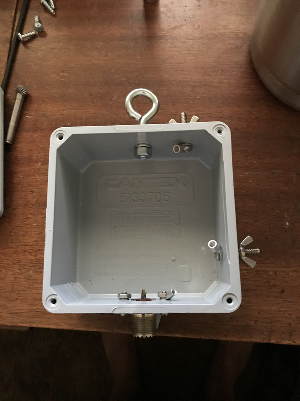
|
|
|
|
[#16]
Quoted: Thanks again OP for inspiring me to give this a try. I have my housing ready to go. As soon as my toroids, enameled wire, copperweld antenna wire, and enclosure vent arrive I'll post another pic.https://i.postimg.cc/2jTWHHwG/A7-DCF777-0-D69-46-CD-924-D-0-CE074-F67-E1-A.jpg Good deal! Since you're building with a focus for higher power, check out Steve Ellington, N4LQ's videos on Youtube, he's done a lot of setup testing for permanent, high power installs. IIRC, he uses 3 cores and 14 gauge enamel wire to make the transformer, and uses both a ground rod at the transformer and a high power RF choke on the coax several feet from the feed point to give the best performance and lower noise. |
|
|
|
[#17]
Quoted: Good deal! Since you're building with a focus for higher power, check out Steve Ellington, N4LQ's videos on Youtube, he's done a lot of setup testing for permanent, high power installs. IIRC, he uses 3 cores and 14 gauge enamel wire to make the transformer, and uses both a ground rod at the transformer and a high power RF choke on the coax several feet from the feed point to give the best performance and lower noise. I have watched his videos, and am building my transformer and choke accordingly. My wire will be cut for 40 meters, and set up as a sloper. |
|
|
|
[#18]
Quoted: I've bought a few toroids from kf7p.com. 240-43's are about $6.20 ea. 5 lb or less generally ships priority mail. GREAT website! Lots of great info on grounding etc. I plan on making one of these antennas as soon as the heat breaks. Thank you! |
|
|
|
[#19]
OP, can you post a pic of your compensation coil? I’m still waiting on my toroids, but want to add this coil for 10m if it’s going to help even a little.
I’m also wondering if I’ll need the counterpoise, as my entire yard has 18 wires buried in a fan pattern underneath where the antenna will go up. The center of the fan is about 20 feet away from where the feed point will be, wonder if I should run a wire & connect it, or if just the wire being beneath it will be enough. I guess more counterpoise is better, but not sure. |
|
|
|
[#20]
Quoted: OP, can you post a pic of your compensation coil? I'm still waiting on my toroids, but want to add this coil for 10m if it's going to help even a little. I'm also wondering if I'll need the counterpoise, as my entire yard has 18 wires buried in a fan pattern underneath where the antenna will go up. The center of the fan is about 20 feet away from where the feed point will be, wonder if I should run a wire & connect it, or if just the wire being beneath it will be enough. I guess more counterpoise is better, but not sure. I covered the coil in shrink wrap on mine, but here it is. I just drill a few holes in a small bit of thin wall PVC pipe that's about 1 inch OD, and then pass the aerial wire through one hole, wrap it around tight with the wraps touching, and then back through the the other hole. A couple small zip ties hold it in place.  As for the counterpoise/ground situation, if you have a decent ground field, try that first, sometimes a good ground rod or four, or a radial field can give you a ground to keef RF from coming back down the coax. Otherwise, it seems like the other good options are to either insert a common mode choke inline with the coax 0.05-wavelengths of the antennas lowest band (ex, 80m = about 13.5 ft) from the 49:1 transformer. This option lets the coax shield in that 0.05 wave section act as your counterpoise. Otherwise, you attach a 0.05-wave long counterpoise to the ground side of the transformer, and insert a common mode choke almost immediately after the 49:1, so no coax shield used as the CP, just the CP wire. The setup with a really good ground can possibly eliminate the need for any CMC, but it still doesn't hurt to have and can help tamp down background noise. I always have a CMC when I use this antenna, even portable. I use the short-coax-piece's-shield-as-the-counterpoise method. |
|
|
|
[#21]
Quoted: OP, can you post a pic of your compensation coil? I’m still waiting on my toroids, but want to add this coil for 10m if it’s going to help even a little. I’m also wondering if I’ll need the counterpoise, as my entire yard has 18 wires buried in a fan pattern underneath where the antenna will go up. The center of the fan is about 20 feet away from where the feed point will be, wonder if I should run a wire & connect it, or if just the wire being beneath it will be enough. I guess more counterpoise is better, but not sure. @my65pan A radial field is part of the antenna and needs to be connected to the shield side of the coax. The RF field that flows between the radial wires and the antenna element is what radiates. 73, Rob |
|
|
|
[#22]
Decent chokes aren't hard to build. This one consists of rg316 wrapped on a type 31 core & housed in a weatherproof box from Lowes.
|
|
|
|
[#23]
Quoted: @my65pan A radial field is part of the antenna and needs to be connected to the shield side of the coax. The RF field that flows between the radial wires and the antenna element is what radiates. 73, Rob Not so sure about that, from W8JI: “A grid of conductors parallel to a dipole, laid on earth or suspended above earth, is often referred to as a counterpoise. After all, the word "radial" hardly fits a group of parallel wires with no real connection to the antenna's feed terminal. Counterpoise, in popular Ham radio conversation, has always described a conductor or group of conductors serving as an RF ground.” |
|
|
|
[#24]
Quoted: Decent chokes aren't hard to build. This one consists of rg316 wrapped on a type 31 core & housed in a weatherproof box from Lowes. http://www.skhowell.com/images/type-31-choke.jpg Yes, I’m winding mine with RG-400. |
|
|
|
[#25]
Quoted: Yes, I'm winding mine with RG-400. |
|
|
|
[#26]
Quoted: I use 12 turns of RG-58 a/u on an FT 240-31 core, works great after testing by checking for field strength along the coax. RG-400 is an excellent choice as well! I chose RG-400 for its power handling capability, I want to be able to run 500-700 watts when needed. Same reason I’m using 3 toroids in my transformer. I’ll try putting my choke right at the transformer with my existing counterpoise not connected, try it connected, then try with a .05 counterpoise wire, then try it with the choke .05 away using the shield as a counterpoise & see what works best. Fun stuff! Antennas have always been my favorite aspect of ham radio. I can spend an entire weekend working on antennas & never touch a PTT or key and have more fun than actually being on the air. |
|
|
|
[#27]
Quoted: I chose RG-400 for its power handling capability, I want to be able to run 500-700 watts when needed. Same reason I'm using 3 toroids in my transformer. I'll try putting my choke right at the transformer with my existing counterpoise not connected, try it connected, then try with a .05 counterpoise wire, then try it with the choke .05 away using the shield as a counterpoise & see what works best. Fun stuff! Antennas have always been my favorite aspect of ham radio. I can spend an entire weekend working on antennas & never touch a PTT or key and have more fun than actually being on the air. |
|
|
|
[#28]
Here is a picture to show how I might setup the coax/choke when portable. The 49:1 box is about 5 feet in the air, with the aerial going up to a 30-ish foot branch and then horizontal over to another tree from there. A tent stack and some cord holds the feed point in place.
Then there is a 13.5 ft. piece of coax going from there down to the CMC on the ground, then another 25 f.t of coax to the radio.  |
|
|
|
[#29]
Thanks! I’ll try the choke at the feed point with a .05 counterpoise first & go from there. I have a ground rod to put in at the feed point also. Don’t like the idea of using the shield as a counterpoise, but I’ll try that too.
|
|
|
|
[#30]
You make me want to "borrow back" my HF gear and put something up in my back yard.
|
|
|
|
[#31]
When your doing a lot of FT8 and digital modes be cautious of how you mount it in the box. It will get hot.
|
|
|
|
[#32]
Quoted: Not so sure about that, from W8JI: “A grid of conductors parallel to a dipole, laid on earth or suspended above earth, is often referred to as a counterpoise. After all, the word "radial" hardly fits a group of parallel wires with no real connection to the antenna's feed terminal. Counterpoise, in popular Ham radio conversation, has always described a conductor or group of conductors serving as an RF ground.” Quoted: Quoted: @my65pan A radial field is part of the antenna and needs to be connected to the shield side of the coax. The RF field that flows between the radial wires and the antenna element is what radiates. 73, Rob Not so sure about that, from W8JI: “A grid of conductors parallel to a dipole, laid on earth or suspended above earth, is often referred to as a counterpoise. After all, the word "radial" hardly fits a group of parallel wires with no real connection to the antenna's feed terminal. Counterpoise, in popular Ham radio conversation, has always described a conductor or group of conductors serving as an RF ground.” @my65pan An RF ground is not part of an antenna system or a radial field; though, they may look the same, the difference is in how they are used. I have wires on the ground under my dipole, they are not connected to anything, they are there to reduce ground losses. Picture a dipole, the current flows up the center of the coax and develops an electrostatic field and a magnetic field between the two wires of the dipole, the field actually flows between the two halves of the antenna. When the polarity is reversed (RF is Alternating Current.) the fields reverse in polarity and the process continues with the field flowing in the opposite direction. W8JI will tell you that radiation is due to charge acceleration down a wire. Picture a dipole again but point the center fed wire straight up, ground mount it with the shield side of the wire along the ground (earth) with a 90 degree angle between the two wires. It is still like the air mounted dipole where in the currents still need to flow between the two wires. Thus, the vertical still needs wire on both sides of the coax. In fact, because of 'ground losses' the most efficient coax fed vertical will need 120 radials to keep the RF energy from warming the worms. The point is, the end fed wire will still need some sort of radial field because there must be two sides to the antenna for the RF fields to flow between. The 'end-fed' antennas all use a matching device because the impedance is high at the end of the wire. The current there will be lower than the dipole but it will still need a return path, hence the other side of the antenna. Not trying to be preachy, I just want the theory to be understood. HTH 73, Rob |
|
|
|
[#33]
Quick wire question - Is the 'enamled' part of the internal wiring important? Will I see any weirdness if I use either the insulated hot/common or bare ground from residential 12/3 copper wiring? I think I remember something about the coatings doing weird things with capacitance, but that's just a faint echo in the back of my head.
|
|
|
|
[#34]
Quoted: Quick wire question - Is the 'enamled' part of the internal wiring important? Will I see any weirdness if I use either the insulated hot/common or bare ground from residential 12/3 copper wiring? I think I remember something about the coatings doing weird things with capacitance, but that's just a faint echo in the back of my head. Do not use bare copper wire. It will make a DC short on the first couple wraps where the primary and secondary windings are twisted together, negating the primary winding all together and essecially making it a single winding inductor with a tap at the second turn vs. a primary/secondary autotransformer. You can use insulated wire, but you will take a decent hit in efficiency losses in the core. Enameled wire is the best option because it's thin coating will give better coupling effect. |
|
|
|
[#35]
This is my vacation setup, I’m on the 2nd floor and the unun is hung from the handrail on the 3rd floor where my in-laws are staying. The far end is on a random piece of pvc I found and tied to a fence. A 50f counterpoise is dropped from the unun and run under the antenna.
The sweep looks pretty good on 80 and 40 but pretty bad on 20m (~3vswr.) |
|
|
|
[#36]
Quoted: This is my vacation setup, I'm on the 2nd floor and the unun is hung from the handrail on the 3rd floor where my in-laws are staying. The far end is on a random piece of pvc I found and tied to a fence. A 50f counterpoise is dropped from the unun and run under the antenna. The sweep looks pretty good on 80 and 40 but pretty bad on 20m (~3vswr.) Nice setup! That's similar to what I have found as well with the "random" wire fed 9:1 type end feds, you will get really variable results depending on the orientation and setup, and the length of the counterpoise also plays a big role. That's why they really recommend having a tuner to clean up the SWR a bit. And also the way they disguise the poor efficiency on the lower bands where the wire+CP don't add up to at least a half wave with "good" SWR. They're just really unpredictable sometimes. Still, 3:1 isn't terrible, and you might be able to improve it if you try shortening the CP (even just coil up the end). |
|
|
|
[#37]
FWIW I had better luck with the 49:1 setting on the unun vs the 9:1. The wire was 71ft long and I folded back about 2ft. I have a 12m mast with me but I'm not sure what to do with the radials / CP if I erect it on the upper level of the deck 40ft high. I can have one go down and maybe throw two or three on the roof...
|
|
|
|
[#38]
Quoted: Do not use bare copper wire. It will make a DC short on the first couple wraps where the primary and secondary windings are twisted together, negating the primary winding all together and essecially making it a single winding inductor with a tap at the second turn vs. a primary/secondary autotransformer. You can use insulated wire, but you will take a decent hit in efficiency losses in the core. Enameled wire is the best option because it's thin coating will give better coupling effect. Quoted: Quoted: Quick wire question - Is the 'enamled' part of the internal wiring important? Will I see any weirdness if I use either the insulated hot/common or bare ground from residential 12/3 copper wiring? I think I remember something about the coatings doing weird things with capacitance, but that's just a faint echo in the back of my head. Do not use bare copper wire. It will make a DC short on the first couple wraps where the primary and secondary windings are twisted together, negating the primary winding all together and essecially making it a single winding inductor with a tap at the second turn vs. a primary/secondary autotransformer. You can use insulated wire, but you will take a decent hit in efficiency losses in the core. Enameled wire is the best option because it's thin coating will give better coupling effect. @Amish_Bill You can get this stuff called Kapton tape to wrap the core before winding. The tape will protect the enameled wire from the core.73, Rob |
|
|
|
[#39]
I've used a layer of Teflon plumbing tape on cores before, seemed to work fine.
|
|
|
|
[#40]
@D_Man I spooled up about half the CP wire and my 20m swr went from 3.5 down to a little under 2.0 (at the radio using a tuner.) If the swr is much over 3 my MFJ-939 atu tries to retune in the middle of digital tx's and it's annoying and probably bad for the radio.
|
|
|
|
[#41]
Quoted: @D_Man I spooled up about half the CP wire and my 20m swr went from 3.5 down to a little under 2.0 (at the radio using a tuner.) If the swr is much over 3 my MFJ-939 atu tries to retune in the middle of digital tx's and it's annoying and probably bad for the radio. I wanted to add another version of the EFHW here that could be ideal for people what have limited space to setup or want a shorter wire antenna that still has the ability to work part of 80 meters. This is fundamentally the EFHW described above with a main radiating element cut for a half wavelength on 40 meters (giving you 40-20-15-10 meters), then on the end of that is a loading coil valued at about 110 uH (about 80 turns 20ga. enamel wire tight on a 1.5" OD form) followed by about 6 or 7 feet of additional wire. The coil has enough inductance that it acts like a trap for 40 meters and above so when on those bands, the coil and the wire after it are ignored by the radio, but on 80 meters, the coil acts as a loading coil and combined with that extra wire, gives you access to using the antenna on 80. Now, being so electrically shortened by the coil, the downside is the efficiency will take a hit on 80M, and also your usable bandwidth on that band will be very tight, probably less than 100 kHz.  To tune this one, start a bit long on both wires. Put it up in the air and first trim the longer wire for you ideal match on 40/20/15/10. Then, look where you're at on 80 meters and adjust the length of the shorter wire at the end to find the resonance point you want. Remember, it'll be a tight bandwidth and won't cover the whole band on 80, so you'll either have to choose where you want it, maybe focus on the voice portion or the CW/digital potion, or if you plan to use this as a portable setup, tune the wire so it's long enough to work the bottom of the 80 meter band and plan to adjust the wire in the field buy coiling up the end a bit to get higher in the band. This configuration won't have as good radiating performance on 80 meters as the full 80-meter half-wave version due to the loading, but if you just can't spare enough space to get 135 feet of wire in the air, it can at least give you something for more local and close regional contacts. This is the one I've used to good success as a portable antenna, shown with my low-power 49:1 transformer shown in the OP but now boxed up.  |
|
|
|
[#42]
Transformer is ready. Gonna wait on cooler weather before stringing wire though.

|
|
|
|
[#43]
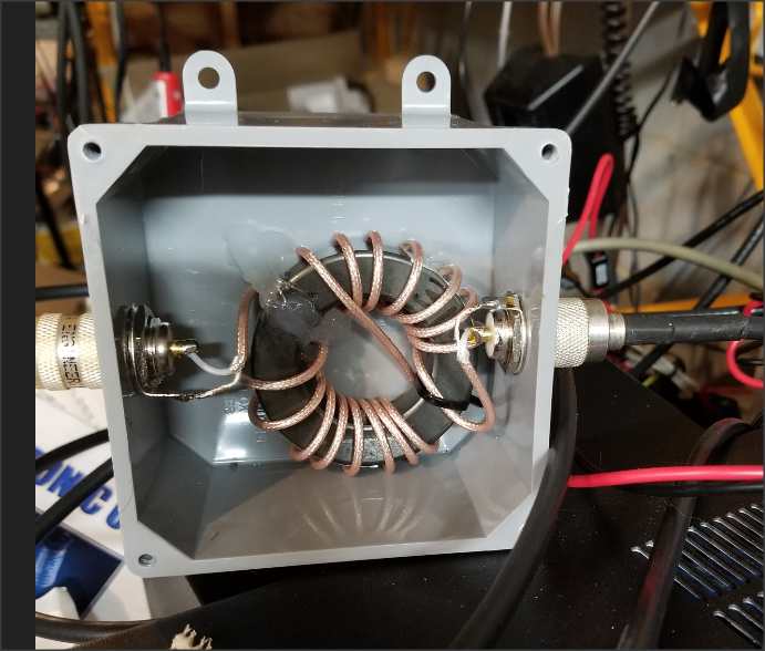
Quoted: Transformer is ready. Gonna wait on cooler weather before stringing wire though. https://i.postimg.cc/K8v0nqMj/50455-A69-A62-F-4-AA2-B2-A8-24421-DDEE428.jpg You have the two twisted windings for the ground side isolated from one another, one to the ground post on the side of the box and one to the shield side of the coax connector. These need to be common to each other somehow, or else it's not an auto-transformer, but rather an isolated transformer. Unless you plan some external connection between the ground post and the coax shield, I would run both windings together to one of those points inside the box, and then a short jumper wire over to the other (or leave them as is and add a jumper between the coax connector and the side post). |
|
|
|
[#44]
I put a switch between the grounds on the primary and secondary. Sometimes it's better as an autotransformer and sometimes not...
|
|
|
|
[#45]
I see what you mean, I’ll reconfigure it tomorrow. How about just scraping the enamel off & soldering the two grounds together in the middle where they separate?
|
|
|
|
[#46]
Quoted: I see what you mean, I'll reconfigure it tomorrow. How about just scraping the enamel off & soldering the two grounds together in the middle where they separate? |
|
|
|
[#47]
Fixed it, I don’t know what I was thinking. Somehow got it in my head that they were connected already by twisting them together.
|
|
|
|
[#48]
This is the site I referenced when I was making unun's: https://www.nonstopsystems.com/radio/frank_radio_antenna_multiband_end-fed.htm
You don't have to connect them together, if you don't you have to use a CP - which to me isn't a problem as I didn't want radiating feedline. My dual tapped unun with the switch on the grounds can operate as the first or last image below. I have two ground lugs, one for each side of the xfmr where the secondary one is isolated from the case unless the switch is flipped. |
|
|
|
[#49]
Quoted: This is the site I referenced when I was making unun's: https://www.nonstopsystems.com/radio/frank_radio_antenna_multiband_end-fed.htm You don't have to connect them together, if you don't you have to use a CP - which to me isn't a problem as I didn't want radiating feedline. My dual tapped unun with the switch on the grounds can operate as the first or last image below. I have two ground lugs, one for each side of the xfmr where the secondary one is isolated from the case unless the switch is flipped. https://www.AR15.Com/media/mediaFiles/68732/BE580DF3-A06A-4F34-A337-3182C24FB545_jpe-1527143.JPG https://www.AR15.Com/media/mediaFiles/68732/928597AC-1B92-43B8-83C9-1985B33BF540_jpe-1527144.JPG https://www.AR15.Com/media/mediaFiles/68732/7FD6C686-499E-4425-9CDB-E049A5D35644_jpe-1527146.JPG Thanks! I’m going to go with the bottom image for starters. Edit: Actually I’m going with a combo of images 2 and 3. Going to have the choke .05 wavelength away from the transformer, and a .05 wire on the ground lug & see how that works. |
|
|
|
[#50]
How did you pick the value of the capacitor?
what voltage rating does the capacitor have? how did you pick the voltage? Where did you order or buy the capacitor? |
|
|
 Win a FREE Membership!
Sign up for the ARFCOM weekly newsletter and be entered to win a free ARFCOM membership. One new winner* is announced every week!
You will receive an email every Friday morning featuring the latest chatter from the hottest topics, breaking news surrounding legislation, as well as exclusive deals only available to ARFCOM email subscribers.

AR15.COM is the world's largest firearm community and is a gathering place for firearm enthusiasts of all types.
From hunters and military members, to competition shooters and general firearm enthusiasts, we welcome anyone who values and respects the way of the firearm.

Subscribe to our monthly Newsletter to receive firearm news, product discounts from your favorite Industry Partners, and more.
Copyright © 1996-2024 AR15.COM LLC. All Rights Reserved.
Any use of this content without express written consent is prohibited.
AR15.Com reserves the right to overwrite or replace any affiliate, commercial, or monetizable links, posted by users, with our own.