|
Posted: 4/5/2011 7:16:20 AM EDT
[Last Edit: thebeekeeper1]
Inside an Image Tube.
Getting a feel for the inside of an image tube can be difficult if you're one of the many who has never taken one apart. This is a quick article on what exists beneath the plastic boot that hides what lies within.
Although we (mostly) all kind of know what's inside of an image tube, have you ever considered what it all means? Having a good image in your mind helps you understand the technology, it's limitations and the scale on which things occur.
So for those interested, here's a brief journey through a modern Gen3 image tube. And for those who like to have a yardstick to measure things by, the average thickness of a human hair is about 100microns, or 100,000nm or 1 million Angstroms.
The Photocathode.
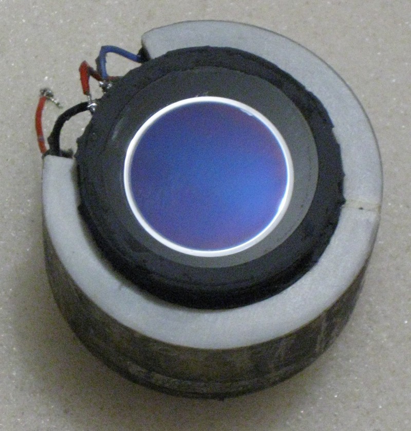
Most Gen3 tubes have this deep blue photocathode below a glass substrate which makes them relatively easy to identify, although late US Gen2 sometimes have similar colors.
The photocathode is a piece of glass around 5mm thick that's clear on one side and on the other they grow a Gallium Arsenide Crystal ( GaAs ) that acts as the photocathode. That is, it converts photons into electrons.
This is straight photoelectric effect. Gallium Arsenide is a semiconductor and you can make electronics out of it. They make very expensive solar panels out of the stuff also. Excellent for satellites and the like where high efficiency solar cells are needed, but the cost of satellites makes using this expensive stuff worth it.
They grow the photocathode right there on the glass faceplate like how mist forms on glass when you blow on it, except it doesn't evaporate. It grows... Just vapor but it builds up over time.
And they build it up like a layer-cake because it's not just a single piece of GaAs.
You might think that in itself is unusual, but there's more to it than that. First of all you know how they coat optics for riflescopes and the likes? Well that glass window is an optic, so they use a coating, approx 1/4 wavelength ( eg, around 200nm ) of Silicon Nitride to act as an antirelfective surface and pass the light on towards the photocathode.
The next layer to go down is an Aluminium Gallium Arsenide layer about 5 microns ( 5000nm ) thick. This acts as a bandpass filter ( above 600nm ).
Next they grow a single crystal of zinc-doped GaAs that's between 1 and 1.8 microns thick. This is the active layer. Then finally they add a monolayer ( think 1 atom thick ) of Cesium and apply oxygen to convert this to Cesium Oxide. It's this change that causes the band-bending of the GaAs and results in the negative electron affinity ( NEA ) that I mentioned in the Gen4 discussion.
That's a simplification of the process, but consider how thick this photocathode is... Then compare it to a Gen2 photocathode that is about 300nm ( 0.3 micron ) thick. Big difference eh?
The MCP.
The Microchannel Plate is the best-known part of Gen2 and Gen3 image intensifiers. These have been around for decades but even now research is going on to improve them.
They take an etchable glass and surround it with a lead-silicate glass, create a boule and draw it through a glass-fiber furnace. They take a bunch of these glass fibers and put them together ( usually into a hexagonal shape ) and draw them once again and once more stack these together and fuse them. Because the fibers get progressively smaller each time they draw them, they end up with a rod made from millions of glass fibers.
They then slice this at an angle - usually about 6 degrees and into slices approximately 0.3 to 0.4mm thick. These are then etched to dissolve the etchable glass and this produces millions of small holes in the plate at the same angle at which the bundle was sliced. These are the microchannels.
They coat the outsides with a conductive layer of nichrome and the MCP is finished, ready to use ( after a little scrubbing, but that's not for this explanation today ).
HOWEVER, the Gen3 MCP also has an ion barrier film. They float laquer on water and create a self-supporting laquer film by lowering the water onto a supporting frame and letting the laquer dry. Then ( in a vacuum ) they place this on the MCP, coat it with Aluminium Oxide to a thickness of about 30 Angstrom ( 3nm or 0.003 microns ) and sinter this by baking to create an aluminium oxide film over the input side of the MCP.
Kind of like wetting pastry, coating with spices and baking away the moisture.
At 30 angstrom the film will stop any electrons that don’t have enough voltage to push their way through. This is known as the dead-voltage and the result is that not all electrons get through the film. The film stops damaging positive ions that are developed in the MCP during operation from reaching the photocathode, but the downside is that some electrons are stopped from getting to the MCP also.
This effectively reduces the sensitivity of the tube by around 50 percent in a standard filmed tube.
The Screen.
There’s a fair bit about screens that aren’t widely known. The technology dates back to vacuum tubes before WW2 and it’s basically the same as the old CRT TV sets that everyone on this forum knows well.
They call them phosphor screens because they convert electrons to light, but that doesn’t mean they use phosphorus.
In fact, they make them underwater. Imagine mixing all the stuff you need and shaking it up, pouring it into a big glass with the screen substrate and allowing it to settle. That’s how they do it. All the phosphor particles settle on the glass or fiber plate that forms the screen.
Add some sodium silicate or potassium silicate as a binder, some barium acetate as an electrolyte and when it’s settled, let it dry in the air. The optimum thickness for a screen using 8 micron particulates is around 8 micron’s thick. This will allow a resolution of over 100 lp/mm - sufficient for the resolution of the MCP.
Then they deposit an aluminium coating over the screen in argon gas to provide suitable conductive medium and to keep the light from getting back to the photocathode for obvious reasons.
There are other ways to do it, but this gives you an example and probably impresses on you that these guys would make good chefs.
There are quite a number of screens that might be used on a gen3 tube. Two common ones are P20 and P43.
Phosphor screens exhibit two forms of function. Fluorescence and Phosphorescence. Fluorescence is when it lights up when struck by electrons. Phosphorescence is how long it remains lit up afterwards.
P20 is a yellow-green phosphor with a peak output at 560nm. It decays to about 10% brightness in 0.2ms.
P43 is also a yellow-green phosphor with a peak output at 544nm and decays to about 10% brightness in 1.2ms.
This is probably why P43 is more popular as a screen. It’s extended phosphorescence allows the image to appear brighter to the user under extremely low light conditions.
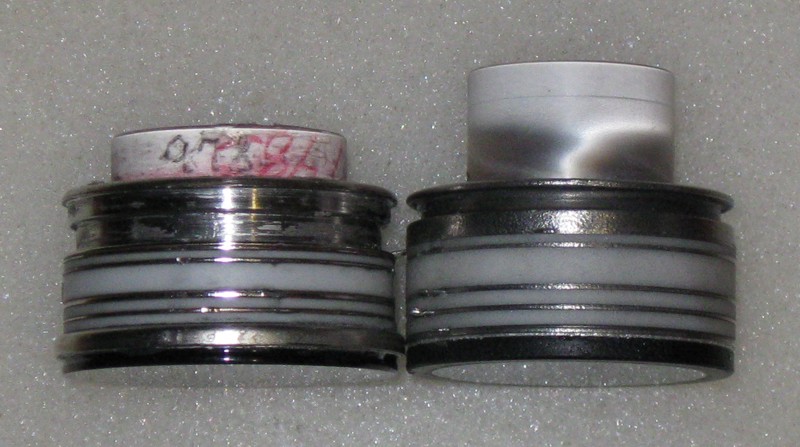
The Fiber Twist.
( as show above, shorter on the MX10130 that does not have a twist in the screen FO plate. The twist can be easily seen in the MX10160 on the right. )
Remember the description of how the MCP is made? Well the fiber twist is made the same way, except it isn’t etched.
Fiber Plate is an invention from the 1950’s and it was what made the first starlight scopes possible. It also allowed the glass to be shaped and this reduced the distortion of the tubes as well.
Well, they grab a piece of rod made from the stuff, heat it and twist it 180 degrees. This allows the image to be inverted which simplifies the optics of the scope in which the tube is to be used.
Power Supply.
The power supply is a separate component, but it too fits in the package. It takes 3v and runs this through an oscillator and after building up the voltage to a higher level, it’s put through a cockroft/Walton generator (http://en.wikipedia.org/wiki/Cockcroft%E2%80%93Walton_generator ) to build up the voltages to the required level.
There are three outputs (and one ground) from a power supply.
1. The Screen. This is kept at a potential of around 5000v.
2. The MCP input. This is typically kept at a potential between -200v and -800v.
3. The Photocathode. This is typically kept at a potential around 800v lower than the MCP input - so around -1600v.
The MCP output is kept at ground potential.
In thin-filmed tubes, the photocathode is at about -600v beneath the MCP input and in filmless, it’s approximately -200v below. This voltage variation is most likely necessary to ensure that most electrons make it through the film.
Power consumption of the power supply is around 40ma at 3v. Not much.
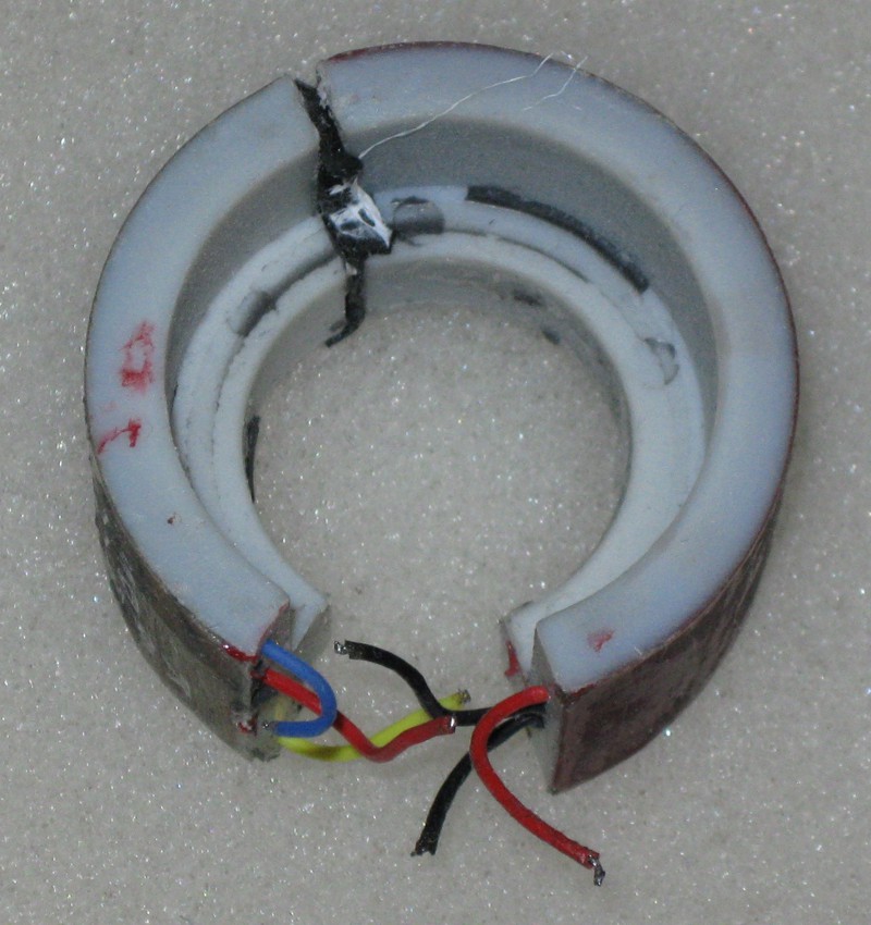
The above is an example of a Gen2/3 PSU. The three high voltage lines can all be seen on the left. Yellow is the screen, Red is the MCP and Blue is the Photocathode.
Assembly.
Now you have all the parts, it’s time to put them together. Under a vacuum, they use bellows to hold the pre-assembled parts apart while they activate the GaAs photocathode ( The Cesium oxidising process ) and then they fit the parts, separating the sections with ceramic rings holding apart metal rings that keep everything in place.
Indium ( a soft metal like solder ) seals allow for air-tightness and the process is complete. Small metal tabs stick out through the metal rings and these are soldered to the power supply. The tube is filled with an insulating compound, an elastomer made from silicon. This is also known as the potting.
Then the tube is housed in a suitable form ( eg, Thin Anvis ) for it’s intended purpose.
Inside, the parts are now very close. The photocathode is within a few 10ths of a millimetre of the MCP and the screen is just a few mm away.
This is why the tubes can be damaged by shock. The MCP can flex enough to actually touch the Photocathode. With the voltages involved, this will burn a hole in the photocathode and damage the tube permanently.
Well, I hope this has been interesting. I’ve simplified this process as much as I can. If you have questions, please let me know.
If you would like to get deeply into what makes an image tube tick, I’d recommend a book called "Image Tubes” by Illes P Csorba. It’s not in print anymore but often shows up on Amazon.com as a secondhand book.
David
<Edit to bold the title. ––tbk1> |
|
|
|
|
[#1]
Excellent piece, David! Combined with your earlier one on filmless tubes, you have provided a clear explanation of the technology and, for me at least, made clear why the tubes are such a large part of the overall cost. Thank you for putting these articles together. Do you see the future being more advances in this type of technology or will digital move into the mainstream with better capabilities and better shock tolerances? |
|
|
|
|
[#2]
David, long overdue thread like this. VERY well done!
Vic |
|
|
|
|
[#3]
Tube killer !!
 Note to self. David likes to take things apart... Note to self. David likes to take things apart... Very nice job and well done. |
|
|
|
DEU
|
[#4]
Fantastic read! I always wondered how they made the MCPs, now it's at least partially clear.
What insanely complicated technology is behind all this ! |
|
|
|
[#5]
Great stuff David!
This should be included in the posts that don't go away, sticky or tacked, whatever its called.. Brent |
|
|
|
|
[#6]
Originally Posted By b_rogers:
Great stuff David! This should be included in the posts that don't go away, sticky or tacked, whatever its called.. Brent Agreed. |
|
|
|
|
[Last Edit: TNVC]
[#7]
Originally Posted By Barliman:
Excellent piece, David! Combined with your earlier one on filmless tubes, you have provided a clear explanation of the technology and, for me at least, made clear why the tubes are such a large part of the overall cost. Thank you for putting these articles together. Do you see the future being more advances in this type of technology or will digital move into the mainstream with better capabilities and better shock tolerances? Great question....I well let David answer this first. I have my opinions I will reserve for a bit. |
|
|
|
|
[Last Edit: Dino1130]
[#8]
I think digital will eventually replace tubes. Not next week but in the years to come. Tubes will be around for along time.
|
|
|
|
|
[#9]
Originally Posted By TNVC: Originally Posted By Barliman: Excellent piece, David! Combined with your earlier one on filmless tubes, you have provided a clear explanation of the technology and, for me at least, made clear why the tubes are such a large part of the overall cost. Thank you for putting these articles together. Do you see the future being more advances in this type of technology or will digital move into the mainstream with better capabilities and better shock tolerances? Great question....I well let David answer this first. I have my opinions I will reserve for a bit. But based on what I have seen and heard of, and cross-pollinating those ideas with a few other technologies currently being sought by the US .MIL, I'll have a stab at it. I think tubes will be here for a long time and at least another decade without decline. Digital technology has already passed tube technology, but it still has a lot of issues, some of which are unlikely to be resolved in the near future. Digital technology has several advantages over tubes. Extended sensitivity ( right up into SWIR ) is one - They can see through smoke and battlefield obscurants which tubes cannot. They do not suffer from halo and can be multi-band, mixing SWIR, MWIR and LWIR into a single unit. They are also useful with out-of-band laser aiming devices and markers. There is also the added capability of allowing tactical information to be superimposed over the tube data. They already use such systems to allow HALO drops with pinpoint accuracy at night and to identify other information such as terrain trails and target information. Just like in video games, but that's a lot of what is actually being built today. I'd love to see where the state of the art development is taking place, but the best I can do is put together the pieces that I receive from multiple news sources to get that picture. However, even without having a unit, I am familiar with other digital devices and already know many of their weaknesses. Firstly, they suffer from a lack of dynamic range. Daylight cameras are already several generations into the process and still suffer from limited dynamic range. Want an example? Take a picture through a NOD and see what information you lose when you blow the image up. A LOT of detail is lost, especially where significant contrast occurs in a small area on the screen. Our eyes can cope with this and tubes are far more linear than Digital is even today. Also digital doesn't last very long. Great for brief spec-ops type duties, but not for an extended campaign. Batteries and power supplies are already a logistical problem for the US and will be for all countries. Tubes only sip power. Digital sucks it dry. Even then, Modern 80 degree FOV tubes are taking the technology in new directions and it will take a while for digital to catch up because the goalposts are moving all the time. Digital has more to go wrong. Dirt, vibration, everything. One of the biggest failure in tubes today is the power supply and that's simple tech. Now add a whole heap of high-tech processing and think about what more can go wrong with digital. Finally, cost. When digital gets to the sub-$1000 mark (equivalent to today's costs ) and can beat tubes, then it will make sense to go digital, but only from a purely cost perspective. The US is struggling to give it's troops the edge. But until they include a set of batteries with every MRE, then keeping them in the field is going to be a huge problem. Not to mention the green people will want us to make the batteries green-friendly on that kind of scale. Litter battlefields with all kinds of stuff sure... Bodies, even depleted uranium, but no, not batteries... Crazy greenies.So looking across all of the issues with a broad view, I think tubes are here for a while. The US us still struggling to supply it's own forces with better technology on an ongoing basis and we're still only talking enough technology for the conflicts it's currently involved in... Imagine if it ever got involved in a REAL war, defending itself from an aggressor (admittedly not likely, but it still requires preparation )... If tubes are cheap, then there will be a place for them for many many years to come After all, what really defines a technologies availability is it's purpose and use. So let's look at the PVS-4 for a good example. It's 33 years old technology now, yet they only stopped "officially" making tubes for it in 2002 and are still unofficially making tubes and assemblies for it as recently as this year. It's gen 2 and was surpassed in 1996 by the AN/PAS-13 but it's still in use today. So to put some numbers to it, I think tube tech will still be around in 10 years time though we will be evaluating it against technology that's long since surpassed it even in as little as years. We will be wondering why they are still making such huge number of tubes and chatting about the new TNVC WASP24K rumours ( Quad band with ballistic doppler-shift windage and drop compensation no doubt ) And then long after the US is no longer the major consumer of tubes, you an be sure that tube manufacturers will be exporting huge volumes to overseas militaries looking to upgrade their mostly Gen2 deployments of around 25% with modern Gen3 FOM unlimited technology. After all, it still won't be able to see modern US out-of-band aiming devices and smoke is easy to drop before a fight. David p.s. For SHTF scenarios, Tube technology will still be the #1 tech... Batteries are still a problem under those circumstances... |
|
|
|
|
[#10]
"
And then long after the US is no longer the major consumer of tubes, you an be sure that tube manufacturers will be exporting huge volumes to overseas militaries looking to upgrade their mostly Gen2 deployments of around 25% with modern Gen3 FOM unlimited technology. After all, it still won't be able to see modern US out-of-band aiming devices and smoke is easy to drop before a fight. David p.s. For SHTF scenarios, Tube technology will still be the #1 tech... Batteries are still a problem under those circumstances... "
____________________________________________________________________________________________________________________________________________________________________________________________ WOW! That's something more than a stab - more like surgery! I know this is just "your opinion" but you have done a great job of breaking into logical and consistent areas across the technologies, the technology limits and the potential users moving forward. I'd like to make an intelligent comment ... but I am going to have to think about this for a little bit before that can happen. "Green" battlefields ... an oxymoron thought up by morons (i.e. the current crop of radical ecologists - compared to 40+ years ago I was a founding member of a ecology group in my hometown, we did volunteer paper collection, river and roadside clean-ups, worked the political levers while the radical ecologists were predicting the next ice age ... the changes over that time period have been astounding ... the air and water is much cleaner, the conciousness changed and two years ago my kids got to see a local family of bald eagles flying over our place outside a major city) Batteries - the "must have" accessory for literally everything. I keep my extra AA's in my stock and my 123's in my Ergo grip. I solved my wife grumping about extra batteries by getting her a 100+ lumen flashlight. Thank you! And the other regulars here who share your knowledge with the rest of us. |
|
|
|
|
[#11]
Finally got around to reading this David, and found it most informative!
I'll probably have to do so another couple of times before being able to make an intelligent sounding inquiry. |
|
|
|
TX, USA
|
[#12]
I now understand why NV really hasn't dropped in price. It's so technical to produce. Not just a computer sodering wires. If you'll excuse me I'm going to re-read this now.
|
|
|
GBR
|
[Last Edit: bazzer]
[#13]
I thought that they grew a single crystal of GaAS and then onto that the band pass AlGaAs layer was grown and then an etch stop layer and then a capping layer. The layers are grown by MOCVD, the AlGaAS can be doped to allow better blue response for desert warfare.
The wafer is then bonded onto a Borosilicate face plate that is a bullseye in that all non light transmissive surfaces are blackened through hydrogen firing in a Hydrogen furnace. The zinc dopant increses the optical length of the electron travel through the substrate but help to increase the chances of a successful valance band bending emission if I remember rightly, thus the zinc dopant is increase towards the output that is Ceasiated. The arse end of the Gallium Arsenide has depleted layers caused by the etching and is thus heat treated in high vacuum to reassurt the stoichiometery, I think they may hydrogen fire it or something ? Getters such as Titanium and Niobium or Tantalum are added to catch poisonous emmisions from retained atoms and secondary ions, aluminium oxide is bonded by the flotation method onto the MCP to act as an ion barrier. With regards to digital NV, silicon doesn't have anything like the quantum efficiency of GaAS, however it does extend into the IR band further. A digital Gen 3 bonded to an IC chip would be good if we could get them as you could use the time delay to saturate the detector and then clean up the image, this is available and being used. |
|
|
AUS
|
[#14]
Hello Dave!
Just wanted to bring up a potential error ive found in most IIT literature pertaining to what is going on at the phosphor screen. Most literature states it is fluorescence occuring at the screen, I do not believe that is correct as florescence is stated as being "the emission of light by a substance that has absorbed light or other electromagnetic radiation" Now since the phosphor screen in this case is being hit with electrons which are not electromagnetic waves then it would fall under the category of Cathodoluminescence! Which is described as "electrons impacting on a luminescent material such as a phosphor, cause the emission of photons which may have wavelengths in the visible spectrum" I do believe there is also a difference between phosphorescence and the short term afterglow of a phosphor's luminescence which is another can of worms. I am sure if what I am saying is incorrect then someone will be along shortly to give me an interweb beat down, but i am pretty certain i am on the money with this one. Fluorescence Cathodoluminescence |
|
|
|
[#15]
Having just completed an undergrad degree in computer engineering, it's absolutely fascinating how incredibly similar the process of making a NV tube is to making an IC.
From the material to solder, this is absolutely brilliant. Given all this, I'm almost surprised that companies like Intel aren't making tubes. |
|
|
|
CA, USA
|
[#16]
Here are some pics and 3D Xray scans I am using in this week's upcoming TFB Friday Night Lights article. I reference this pin post (copy and pasted) as well as linked and credited David.
Cross-sectioned image tube  Micro Channel Plate encased in acrylic. 
 3D Xray scans of my dead Intevac tube. 


dead mufasa |
|
|
|
[#17]
thats cool, i'll definitely keep an eye out for the article.
|
|
|
|
CA, USA
|
[#18]
Here is the article.
https://www.thefirearmblog.com/blog/2020/02/21/friday-night-lights-inside-a-night-vision-image-intensifier-i%c2%b2-tube/ |
|
|
|
[#19]
Interesting
|
|
|
|
IL, USA
|
[#20]
hi
i am wondering if anyone can identify these two i think image intensifier tubes?? what style, model, type, value, any info would be helpful please???? the bag they were in was labeled "2ea new" so i am assuming these to be new. thank you in advance for any assistance. I CAN'T FIGURE OUT HOW TO ATTACH PICTURES???? |
|
|
 Win a FREE Membership!
Sign up for the ARFCOM weekly newsletter and be entered to win a free ARFCOM membership. One new winner* is announced every week!
You will receive an email every Friday morning featuring the latest chatter from the hottest topics, breaking news surrounding legislation, as well as exclusive deals only available to ARFCOM email subscribers.

AR15.COM is the world's largest firearm community and is a gathering place for firearm enthusiasts of all types.
From hunters and military members, to competition shooters and general firearm enthusiasts, we welcome anyone who values and respects the way of the firearm.

Subscribe to our monthly Newsletter to receive firearm news, product discounts from your favorite Industry Partners, and more.
Copyright © 1996-2024 AR15.COM LLC. All Rights Reserved.
Any use of this content without express written consent is prohibited.
AR15.Com reserves the right to overwrite or replace any affiliate, commercial, or monetizable links, posted by users, with our own.