|
[#1]
Rewiring the airsoft PTT is easy enough, usually just need to swap around a couple wires.
But after you do that you still will need a preamp circuit to fix the impedance mismatch. Without that, your transmit audio will be very quiet on the receiving radios. |
|
|
|
[#2]
Thanks, yeah I know about the impediance. But as of now, the chinese airsoft PTT is not working properly. Weird audio. Google tells me that is because it is wired differently than a pair of real headphones, thus I wanted to know if anyone could instruct me in how to properly wire the PTT. Once that is done, sorting the impediance issue is easy as pie. But right now, it's not working and it's not the impediance.
|
|
|
|
[#3]
Quoted:
Thanks, yeah I know about the impediance. But as of now, the chinese airsoft PTT is not working properly. Weird audio. Google tells me that is because it is wired differently than a pair of real headphones, thus I wanted to know if anyone could instruct me in how to properly wire the PTT. Once that is done, sorting the impediance issue is easy as pie. But right now, it's not working and it's not the impediance. Otherwise, it just is a matter of trial and error. The wire going to the PTT is fine if it already triggers the radio transmit, and the second wire coming from the switch should be the ground line. So all you have to do is play around swapping the four leads on the headset connector jack around and testing it until it works. It's a messy way to do it, but if you don't have a multimeter to test what wires connect where, it's a simple option. Also, is it possible to open the radio connector end and see if there is a circuit board in there where the wires connect? That would make it easy to see what color corresponds to what at the radio. |
|
|
|
[#4]
Okay, I managed to hobble something together, opening the motorola pinout, finding which wire went to which pin, and which pin did what. Played around a litte, and changed places on a lot of things. IT works now, at least incomming traffic is clear as day. I am going to need to wait until my components are delivered to make an amplifier for the mic, and then test that.
Any chance you got a wiring scheme for the female nexus? It's numbered 1-5. On 1 the PTT is, as Motorola radios use a separate PTT pin. Normally it would be 4, I think. So if you know which wire goes on which number for a NATO wired plug, that would be much appreciated. Right now, the way I figured it out from the pinout, White - PTT Red - SPK- Yellow - SPK+ Green - Mic ? Black - Mic? I've been unable to assertain which is negative or possitive on the microphone, but from what I know previously, that is less important as long as they go to a mic connector, please correct me if I'm wrong. |
|
|
|
[#5]
Here is the standard NATO scheme for the Nexus TP-102 plug (on the left). Not sure how that matches up to the numbers on your reproduction unit, so you'll have to find out but on the real Nexus TJ-102 type jacks, contact #1 is what mates with the tip of the plug, and it goes back from there.

From my experience with Moto Jedi and Saber series radios, they usually use these 5 wire leads that run up to the PTT box: PTT (from OPT. select pin on radio) SPK + SPK - MIC GROUND So the two you have as "Mic(?)" are likely the MIC lead and the common Ground. I always wire them up so the common ground lead at the radio matches with the "MIC-" lead on the TP-102 plug, and the PTT button will also close to the Ground lead back to the radio as well. To find out which of your 2 unknown pins is the common ground, mach the color of the wires to the pin on the radio's connector that goes to the ground pin. Based on this diagram, ground should be Pin #7, so have both the tip contact from your headset (MIC-) and the output side of the PTT switch go to the wire that's on Pin #7. The MIC lead will go to Pin #4 on the radio. 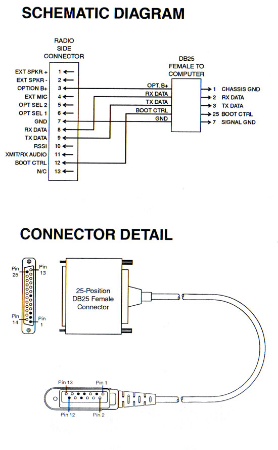
|
|
|
|
[#6]
Yeah, those are exactly the pictures I used. But what I mean is if you have a qiring diagram for Nexus female.
Like what terminal 1-5 corresponds to. As this became guesswork, due to me not knowing which terminal on the female represents what on the plug. Now, I don't have it in front of me, but I'm pretty comfortable saying that Pin 7 is empty on this PTT. So finding which is Mic and which is ground is rough. Like I said, it's not in front of me, but if memory serves Green connected to Pin 4, ext mic. Black connected to 5, opt sel2. But anyways, what I am really looking for now is a wiring scheme for the female nexus in the PTT, it makes it so much easier if I have it clear as day which number on the terminals corresponds to which number on the tp120 plug. |
|
|
|
[#7]
Quoted:
Yeah, those are exactly the pictures I used. But what I mean is if you have a qiring diagram for Nexus female. Like what terminal 1-5 corresponds to. As this became guesswork, due to me not knowing which terminal on the female represents what on the plug. You have a Chinese airsoft replica, so I cannot tell you if #1 on yours is the same as #1 on the real jack. You will have to find that out. If you have a multi meter, put it in continuity check and match up the solder points with the contact pads in the socket. |
|
|
|
[#8]
I can tell you that (5) on the plug does correspond to the "top one" connecting to the base of the tp120 plug. At least if I assume it goes in a straight line from the Terminal.
I can also say that 1, which is the PTT, is "somewhere" as I can't tell where it goes, but number 2 is the bottom one, if I can see in a straight line with a flashlight :) And please check out my last post again, as it's heavily edited now. But hopefully it will all work out now. But thanks for confirming for me that at least when it comes to a real nexus female, it is numbered same as the tp120 plug. I guess next step is waiting for the stuff for the amp, build it and install it and see where we're at then, as I can now recieve clear as day, all the artifacts and distortions are gone. Frickin shame there's no good REAL PTT's for the motorola, with built in amps. It's all homemade airsoft stuff being sold at extortionate prices. |
|
|
|
[#9]
If your plug has 5 wire solder points, that's unusual compared to the real one. It's a 4-contact jack, so the 5th must be either an unused point or doubles with another one. Could you post some pictures? Do you have a multi meter to see if any of those 5 contact points are shorted together in the socket?
My guess is they designed the 5th pad to be a solder point for the wire that comes from the PTT switch? It likely shorts out to the pin that corresponds to ground or MIC- on the plug. Having that extra solder pad makes it cleaner than soldering two wires to one pad. |
|
|
|
[#10]
It is 5, because as a motorla programming buddy explained it, the GP300 series require a separate PTT pin and cable.
I just read your last post, no, it is a "live" terminal. It has it's own "connection pad" inside the female plug. I've checked. |
|
|
|
[#11]

|
|
|
|
[#12]
Quoted:
It is 5, because as a motorla programming buddy explained it, the GP300 series require a separate PTT pin and cable. Got it, give me a few to map it out for you. |
|
|
|
[#13]
Sorry, I tried. Photos just don't come out well.
But as I said, incomming sound is now great. We'll just have to wait for my components to test with amplifier to see if the mic is properly wired. If not, back to the drawing board, but as it is now, when I scream into the mic, I can faintly hear it pretty clear in the other radio. But like my buddy said. The motorola requires it's own PTT terminal. |
|
|
|
[#14]
Quoted:
Sorry, I tried. Photos just don't come out well. But as I said, incomming sound is now great. We'll just have to wait for my components to test with amplifier to see if the mic is properly wired. If not, back to the drawing board, but as it is now, when I scream into the mic, I can faintly hear it pretty clear in the other radio. But like my buddy said. The motorola requires it's own PTT terminal. In your image, is that wiring pattern as it was received or after you moved the wires round to get the receive audio working? |
|
|
|
[#15]
That was in between. I hadn't quite gotten it to work. After that photo I think what I switched was Black and Yellow.
I just tested this with wifey at home. Even when screaming into the microphone, the sound is like a whisper and pretty bad. Could just be background distortion messing up the sound since it's so low, but I def need an amp circuit, and I have a very good picture of one. So soon as my components arrive, I'll make one and test it again. A thought from just now, is that when I do get the amp circuit built, I should def change places on Black and Green. Just to make sure Green (Ext Mic on motorola pin out) goes to Mic+ |
|
|
|
[#16]
Are you using this circuit? If so I'll try to map out what I think you need including the parts:

|
|
|
|
[#17]
I'm using this model
Already ordered the same components, except my capacitor was a lil bigger. 
|
|
|
|
[#18]
Alright, this should do it. I took a bit of an assumption on the female jack assuming it goes 2-3-4-5 from tip to base of the jack. Included the amp circuit components as well.
The note about the diode or resistor in the radio connector is just to make sure you don't bypass that. It's what tells the radio that there is an external accessory attached and to port the audio out. So long as you don't mess around inside the connector, you should be fine.  Edit to add: If your radio is in the VHF frequencies, transmitting could have some noisy interference both in the signal and in your Sordin headset, something about the amp circuit doesn't play well there. It works well on the UHF and higher frequencies, however. |
|
|
|
[#19]
Yes, the motorolas I've lifted from work are both VHF. So yeah, I expect some type of artifacts. But it will all be good hopefully.
Thank you so much for drawing that up, and confirming what I thought. I've seen a lot of amp circuits etc on google past few days doing research, and most of them connect through the PTT button as well. But then most airsofters do it for Baofeng radios which use Kenwood two pin, which doesn't have a completely separate PTT pin out, like the motorola does. So I'll just go straight on the mic with my amp circuit, and leave the PTT cable alone. I plan on using shrink tubing wherever I can to isolate the amp circuit, and for where it's not practical, I was planning on dipping it in PlastiDip (Which is like a spraypaint for cars etc to give them like a rubber coating, would that work), then I plan on melting glue on my stove, like sticks of melting glue, since my glue gun is a weak piece of shit, and just pour it into the PTT after I am done. Can I ask, are you any decent at programming motorola GP300 series? I got the software and the cable, but fucked if I can figure out how? I just need to change the chanels they are on to something different, and preferably a private net. But the sheer number of options and Tx and Rx and everything just overwhelms me. |
|
|
|
[#20]
Quoted:
Can I ask, are you any decent at programming motorola GP300 series? I got the software and the cable, but fucked if I can figure out how? I just need to change the chanels they are on to something different, and preferably a private net. But the sheer number of options and Tx and Rx and everything just overwhelms me. |
|
|
|
[#21]
Wow, I don't speak radio. Now I feel like a retarded mouth breather. Private line? What do you mean? Simplex? Whaaaat?
Also, do you have any thoughts on the plastidip and glue soluton? |
|
|
|
[#22]
I use a material called conformal coating on the exposed contact parts when I'm done wiring something like this. It's basically a silicone dissolved in a solvent you you can easily brush it on everything and then the solvent evaporates leaving a nice insulating coating. Other options are the ideas you had, and I've used hot glue as well in the past.
As for the programming, sounds like you have a lot to learn on that end. I would look for videos on youtube and such, even if its for other Moto products it should give you some ideas. I will also give the boilerplate warning to make sure you only use frequencies you are legally permitted to. Do not just use random frequencies picked out of thin air, you could cause interference to others. |
|
|
|
[#23]
Hey my friend.
Tried soldering everything together. It did not work. Whenever the PTT works, I get no mic input. Whenever the PTT doesn't work, well, how would I know. Real conundrum. Add to that the worlds shittiest soldering iron. Bought a new set. 30W. I'm afraid in my fucking retardation, I have fried the components, or rather overheated them. I will order more components. but also try reassembling the whole thing on a more easy to handle platform to test the circuit again. |
|
|
 Win a FREE Membership!
Sign up for the ARFCOM weekly newsletter and be entered to win a free ARFCOM membership. One new winner* is announced every week!
You will receive an email every Friday morning featuring the latest chatter from the hottest topics, breaking news surrounding legislation, as well as exclusive deals only available to ARFCOM email subscribers.

AR15.COM is the world's largest firearm community and is a gathering place for firearm enthusiasts of all types.
From hunters and military members, to competition shooters and general firearm enthusiasts, we welcome anyone who values and respects the way of the firearm.

Subscribe to our monthly Newsletter to receive firearm news, product discounts from your favorite Industry Partners, and more.
Copyright © 1996-2024 AR15.COM LLC. All Rights Reserved.
Any use of this content without express written consent is prohibited.
AR15.Com reserves the right to overwrite or replace any affiliate, commercial, or monetizable links, posted by users, with our own.